background image

INSTALLATION MANUAL

Parts marked with "

" are important for maintaining the safety of the set. Be sure to replace these parts with

specified ones for maintaining the safety and performance of the set.

This document has been published to be used
for after sales service only.
The contents are subject to change without notice.

SHARP CORPORATION

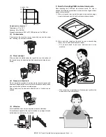
Transit, Installation (using) environment, Note

[1]

CONFIGURATION  . . . . . . . . . . . . . . . . 1-1

[2]

MX-2310U (MAIN UNIT). . . . . . . . . . . . 2-1

[3]

Dehumidifying heater  . . . . . . . . . . . . . . 3-1

[4]

MX-DE12/DE13/DE14 
(STAND/1x500/2x500/3x500 SHEET 
PAPER DRAWER) . . . . . . . . . . . . . . . . . 4-1

[5]

AR-SU1 (STAMP UNIT) . . . . . . . . . . . . 5-1

[6]

MX-FN17 (FINISHER) . . . . . . . . . . . . . 6-1

[7]

MX-PN11A/B/C/D (PUNCH MODULE). . 7-1

[8]

MX-TR12 (EXIT TRAY UNIT)  . . . . . . . 8-1

[9]

MX-FX11 (FACSIMILE EXPANSION KIT) . 9-1

[10] MX-SM10 

(EXPANSION MEMORY BOARD). . . 10-1

[11] MX-PF10 (BARCODE FONT KIT). . . 11-1

[12] MX-FR25U (DATA SECURITY KIT) . . 12-1

[13] MX-PB14 (PRINTER EXPANSION KIT)  . . 13-1

[14] MX-PUX1 (XPS EXPANSION KIT) . .  14-1

[15] MX-PK11 (PS3 EXPANSION KIT)  . .  15-1

[16] MX-FWX1 

(INTERNET FAX EXPANSION KIT) .  16-1

[17] MX-AMX1 

(APPLICATION INTEGRATION 
MODULE) . . . . . . . . . . . . . . . . . . . . .  17-1

[18] MX-AMX2 

(APPLICATION COMMUNICATION 
MODULE) . . . . . . . . . . . . . . . . . . . . .  18-1

[19] MX-AMX3 

(EXTERNAL ACCOUNT MODULE)  . .  19-1

[20] Remote operation panel function 

Enable setting . . . . . . . . . . . . . . . . . .  20-1

[21] Setting, Adjustments, Operation check . .  21-1

[22] Setup and adjustment data recording . . .  22-1

[23] Necessary works before moving the 

machine  . . . . . . . . . . . . . . . . . . . . . .  23-1

CONTENTS

CODE: 00ZMX2310/I1E

DIGITAL  FULL COLOR 

MULTIFUNCTIONAL SYSTEM

MX-2310U

MODEL

Summary of Contents for MX-2310U

Page 1: ... MX PN11A B C D PUNCH MODULE 7 1 8 MX TR12 EXIT TRAY UNIT 8 1 9 MX FX11 FACSIMILE EXPANSION KIT 9 1 10 MX SM10 EXPANSION MEMORY BOARD 10 1 11 MX PF10 BARCODE FONT KIT 11 1 12 MX FR25U DATA SECURITY KIT 12 1 13 MX PB14 PRINTER EXPANSION KIT 13 1 14 MX PUX1 XPS EXPANSION KIT 14 1 15 MX PK11 PS3 EXPANSION KIT 15 1 16 MX FWX1 INTERNET FAX EXPANSION KIT 16 1 17 MX AMX1 APPLICATION INTEGRATION MODULE 17...

Page 2: ...RCODE FONT KIT 1 Unpacking 11 1 2 Installation 11 1 12 MX FR25U DATA SECURITY KIT 1 Unpacking 12 1 2 Installation 12 1 13 MX PB14 PRINTER EXPANSION KIT 1 Unpacking 13 1 2 Installation 13 1 3 Installation 13 1 14 MX PUX1 XPS EXPANSION KIT 1 Unpacking 14 1 2 Installation 14 1 15 MX PK11 PS3 EXPANSION KIT 1 Unpacking 15 1 2 Installation 15 1 16 MX FWX1 INTERNET FAX EXPANSION KIT 1 Unpacking 16 1 2 In...

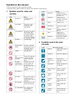
Page 3: ... to scratch NO SCRATCH NO LIGHT Be careful not to expose to light such as the photoconductor and the test chart NO SOLVENT Be careful not to use a solvent in cleaning etc NO DISASSEMLE Do not disassemble Not serviceable Example CCD unit OK GOOD Indicates a correct procedure or result in an adjustment etc NO GOOD Indicates a wrong procedure or result in an adjustment etc NOTE Indicates a note IMPOR...

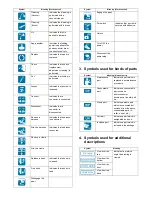
Page 4: ...icates that a harness is secured Remove a clamp Attach a clamp Release a hook Indicates that a hook is released Fix a hook Indicates that a hook is fixed Disengage the pawl Symbol Meaning Work content Engage the pawl Screw lock Indicates that a screw is secured with adhesive Unlock Turn OFF the power Disconnect the power plug Symbol Meaning Kinds of parts Maintenance part Indicates a part which is...

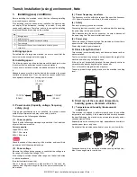
Page 5: ... up transformer is also available In this case the capacity must be great enough for the max power consumption of the machine 3 Power frequency waveform The frequency must be within the range of the specified frequency 2 If power waveform is deformed a trouble may occur 4 Safety Be sure to properly ground the machine Grounding earth connection must be performed before inserting the power plug into...

Page 6: ...m gas Copy quality may be adversely affected and a trouble may be caused 5 Vibration Avoid installation near a machine which produces vibrations If vibrations are applied to the copier machine copy images may be deflected and a trouble may be caused F Note for handling PWB and electronic parts When handling the PWB and the electronic parts be sure to observe the following precautions in order to p...

Page 7: ... Be careful not to leave fingerprints oil grease or other for eign material on the fusing roller and the external heating belt 2 Do not leave the fusing roller in contact state for a long time If these items are neglected a trouble may be generated in the copy and print image quality 2 Transit and delivery A Implements facility and manpower It is recommendable to use a forklift for bringing in the...

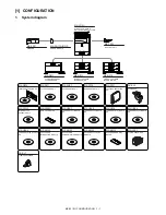
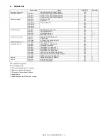
Page 8: ...NSE KIT MX PB14 PRINTER EXPANSION KIT MX PK11 PS3 EXPANSION KIT MX USX1 SHARPDESK 1 LICENSE KIT MX USX5 SHARPDESK 5 LICENSE KIT MX US10 SHARPDESK 10 LICENSE KIT MX US50 SHARPDESK 50 LICENSE KIT MX PUX1 XPS EXPANSION KIT MX PF10 BARCODE FONT KIT MX FR25U DATA SECURITY KIT MX FWX1 INTERNET FAX EXPANSION KIT MX AMX1 APPLICATION INTEGRATION MODULE MX AMX2 APPLICATION COMMUNICATION MODULE MX AMX3 EXTER...

Page 9: ...MX PN11C OPT MX PN11D OPT Printer expansion MX PB14 PRINTER EXPANSION KIT OPT MX PK11 PS3 EXPANSION KIT OPT 1 MX PUX1 XPS EXPANSION KIT OPT 1 2 MX PF10 BARCODE FONT KIT OPT 1 Image send expansion MX FX11 FACSIMILE EXPANSION KIT OPT 3 AR SU1 STAMP UNIT OPT MX FWX1 INTERNET FAX EXPANSION KIT OPT Authentication Security MX FR25U DATA SECURITY KIT OPT Application Solution MX USX1 SHARPDESK 1 LICENSE K...

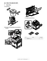
Page 10: ...U MAIN UNIT 2 1 MX 2310U Service Manual 2 MX 2310U MAIN UNIT 1 Unpacking A Unpacking B Removal of the fixing tape and protection material C Check the packed items No Name Quantity 1 Developer 4 2 Operation manual 1 1 2 ...

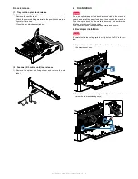
Page 11: ...e label 2 Installation When an optional paper feed desk is connected to the machine unpack and install the paper feed desk then unpack the machine Place the option desk on the machine securely and perform the installing procedures of the machine Place the machine on the optional desk firmly and secure A Developer installation Be careful not to leave fingerprints or oily dirt on the DV roller sur f...

Page 12: ...e developing unit horizontally into the machine in the direction of the arrow until developing unit locks into place Do not push the unit diagonally as contact with the drum may occur causing damage When removing or installing the developing unit put your hand from below the unit and slide it in parallel along the guide At that time be careful not to touch the roller surface When installing the ma...

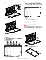
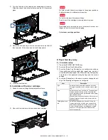
Page 13: ...sure to select all of the four colors K C M Y 6 After the machine completes cycling exit the simulation mode by pressing the CA key on the main unit C Cleaning 1 Cleaning of LSU s dust proof glass Dust from the transfer belt or shutter or some other adjacent part may fall onto the LSU during transport or installation Be sure to clean the dust proof glass before checking the image quality 1 Open th...

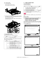
Page 14: ...e Paper Tray Settings key 3 Touch the Paper Tray Settings key to configure the settings These settings specify the paper type paper size and func tions allowed for each paper tray When the Tray Settings key is touched a list appears showing the trays and the current settings 4 Touch the Change key in the above screen to change the set tings The following settings can be configured Item Description...

Page 15: ...imultaneously 1 Enter SIM50 22 mode SIM No Content 26 6 Used to set the destination SIM No Content 26 3 Used to set the auditor specification mode 5 Used to set the count mode of the total counter and the maintenance counter 18 Used to set YES NO of the toner save mode Only in UK and Japan versions For other destination versions this setup is made by the user program 52 Used to set YES NO of count...

Page 16: ... time Display Item Content Display Default NOTE MAIN F C Registration adjustment value main scanning direction Cyan laser writing position F side 1 0 199 0 100 M Registration adjustment value main scanning direction Magenta laser writing position F side 1 0 199 0 100 Y Registration adjustment value main scanning direction Yellow laser writing position F side 1 0 199 0 100 MAIN R C Registration adj...

Page 17: ...heck in the color copy mode To check the copy color balance and density use the gray test chart UKOG 0162FCZZ and the servicing color test chart UKOG 0326FCZZ UKOG 0326FC11 Set the copy density level to 3 in the Text Printed Photo mode Manual and make a copy At that time all the color balance adjustments in the user adjust ment mode must be set to the default center In addition be sure to use the ...

Page 18: ...be seen 4 The color difference in gray balance between the F and the R sides is not so great 5 There are no white and black streaks 6 Color texts are clearly reproduced 7 The background density is not so light Color difference in gray balance between the F and the R sides No white and black streaks Background density Color text reproduction capability Void Void Void Void Void Void Registration Res...

Page 19: ...rence between the F and the R sides is not so great 4 There are no white and black streaks 5 The background density is not so light 6 The black low density gradation is copied slightly Void Resolution Void Low density gradation Resolution Density difference between the F and the R sides No white and black streaks Background density Resolution Resolution Void Void Void Void Resolution ...

Page 20: ...he density changing direction must not be reversed The density level of each color must be almost at the same level Method 2 When the PCL or the PS printer function is not provided GDI model use this method for check Use SIM 67 25 to print the color balance adjustment sheet and compare each process CMY black patch color balance and the black patch to check the color balance The print density must ...

Page 21: ...o the user s request and the color balance is registered with SIM63 7 as the service target if the color balance is required to be adjusted select the SERVICE target The copy color balance adjustment is automatically executed and prints the color balance check patch image If there is any streak or unclear print on the printed check pat tern check the print engine for any problems 5 Press EXECUTE k...

Page 22: ... is automatically performed and the color balance check patch image is printed out If there is any streak or unclear print on the printed check pat tern check the print engine for any problems 8 The initial setting menu of the half tone image correction is dis played Press OK key The initial setting of the half tone image correction is per formed 9 Wait until EXECUTE key is displayed When it is di...

Page 23: ...d perform the manual color balance adjustment ADJ 10C 2 12 Check the printer color balance and density Refer to the item of the printer color balance and density check When satisfactory color balance and density are not obtained from the automatic adjustment by selecting the factory target in procedure 7 change the factory color balance target with SIM 67 26 and repeat the procedures from 1 If a s...

Page 24: ...1 1 5 WH harness DHAI 4701FCPZ BF 1 6 Clamp LHLDW2037FCPZ AC 1 7 Screw XBPS730P08KS0 AB 2 DH POWER 1 3 2 4 7 5 6 Kit name Kit code Price rank No Part name Part code Price rank Q ty Heater kit DKIT 0426FCZZ 120V series DKIT 0426FC11 230V series 1 Heater 120V series RHETP0166FCPZ BA 1 Heater 230V series RHETP0167FCPZ BA 2 Heater mounting plate LPLTM6089FCZZ AK 1 3 Heater mounting plate LPLTM8118FCZZ...

Page 25: ... DHAI 4702FCPZ BB 1 9 Edge holder LBSHC0353FCZZ AC 1 5 6 7 9 2 3 4 8 1 Kit name Kit code Price rank No Part name Part code Price rank Q ty One stage desk heater kit DKIT 0422FCZZ 120V series DKIT 0422FC11 200V series 1 Heater harness 120V series DHAI 4610FCZZ AX 1 Heater harness 200V series DHAI 4757FCZZ 2 Edge saddle LBSHZ0366FCZZ AC 1 3 Clamp LHLDW1225FCZZ AB 2 4 Heater mounting plate LPLTM8096F...

Page 26: ...AC 1 4 Clamp LHLDW1009ACZZ AA 1 5 Clamp LHLDW1225FCZZ AB 4 6 Edge wire saddle LHLDW1503FCZZ AE 2 7 Desk heater mounting plate LPLTM6021FCZZ AQ 2 8 Heater mounting plate LPLTM8096FCZZ AX 1 9 Heater radiating plate PRDAR0087FCZZ AL 2 10 Desk heater 120V series RHETP0144FCZZ BS 3 Desk heater 200V series RHETP0139FCZZ BS 11 High temperature caution label TLABZ5459FCZZ AE 1 12 Screw M4 x 8 XBPS740P08K0...

Page 27: ... of the heater electric component kit 1 External fixture removal 1 Remove the rear cabinet 2 Remove the left cabinet 3 Remove the left cabinet lower 2 Installation of the WH PWB 1 Remove the snap band Attach the supporter and attach the WH PWB 3 WH harness connection 1 Remove the AC cord plate 2 Connect the WH harness and attach the earth wire Pass the WH harness under the CCS WH harness to the sw...

Page 28: ...trol switch label to the rear cabinet B Installation of the heater kit 1 Assembling of the heater unit 1 Attach the heater to the heater mounting plate and secure it with the screw M3 x 6 S tight Attach the clamp and fix the harness to the clamp 2 Attach the heater mounting plate to the T Heater cover and secure it with the screw M3 x 6 S tight 3 Attach the CSS WH harness to the heater mounting pl...

Page 29: ... 10 T tight Pass the harness of the heater through the hole on the main unit frame 3 Fix the earth wire with a screw Connect the connector Pass the WH harness under the CCS WH harness to the switch 3 External fitting attachment 1 Attach the left cabinet lower 2 Install the left cabinet 3 Install the rear cabinet 2 1 CSS WH harness WH harness 1 2 2 1 2 1 2 2 2 2 2 ...

Page 30: ... 1 Remove the paper exit cover 2 Remove the left cabinet 3 Remove the left cabinet upper 4 Remove the rear upper cabinet 5 Remove the rear cabinet 2 SCN WH harness connection 1 Remove the harness guide 2 Connect the SCN WH harness connector to the scanner frame 2 1 1 2 1 2 2 1 1 1 2 2 1 1 1 1 1 1 2 1 2 ...

Page 31: ...e other position of it with banding band 3 Tighten the snap band and cut its tip to approx 5 mm or less Slide the banding band head to the square hole Part that is enclosed by the mark The banding band head and cut tip must not protrude behind the heater fixing plate 4 Removal of the table glass 1 Remove the glass holder Remove the table glass and the SPF glass 5 Installation of the scanner heater...

Page 32: ...he loose scanner heater harness by pulling it in the arrow direction and secure it with the snap band then cut its tip to approx 5 mm or less 6 Move the lamp unit by hand and check that it move smoothly in all movable area Check that there is no interference of the harness of the scan ner heater in the wire and the 2 3 mirror unit 6 Installation of the table glass 1 Install the SPF glass and the t...

Page 33: ...1 Attach the desk heater to the heater mounting plate and fix it with a screw M3 x 4 2 Tray 3 4 heater unit assembly 1 Attach the desk heater to the heater mounting plate and fix it with a screw M3 x 4 2 Attach the edge wire saddle and the desk heater mounting plate to the heater radiating plate and fix them with a screw M3 x 4 Pass the desk heater harness through the edge wire saddle 1 2 2 2 1 2 ...

Page 34: ...e frame Fix the earth wire to the frame with a screw M4 x 8 5 Heater harness 2 attachment 1 Remove the mounting plate 2 Remove the connector cover 3 Attach the edge saddle Attach the heater harness 2 and pass it through the edge saddle Pass the earth wire through the edge saddle and fix it with a screw M4 x 8 4 Attach the connector cover 5 Attach the mounting plate 1 1 1 1 2 3 1 2 1 1 1 2 2 1 1 3 ...

Page 35: ...ater unit for the tray 2 through the hole in the frame Attach the heater unit for the tray 2 to the frame and fix it with a screw M3 x 6 2 Attach the clamp to the frame Connect the harness of the heater unit for the tray 2 to the heater harness and pass it through the clamp 3 Attach the high temperature caution label to the paper feed tray 2 8 Tray 3 4 heater unit attachment 1 Pass the harness of ...

Page 36: ...erature caution label to the frame 9 Connection to the machine 1 Remove the rear cabinet cover of the machine 2 Connect the heater harness to the machine harness 3 Attach the rear cabinet cover of the machine 10 Right rear cabinet and rear cabinet attachment 1 Attach the right rear cabinet and the rear cabinet 11 Paper feed tray attachment 1 Attach the paper feed tray 1 2 2 1 3 3 3 3 2 1 ...

Page 37: ... switch 2 Measure the resistance value between the earth terminal and the AC terminal L side and between the earth terminal and AC terminal N side with the circuit tester and confirm they are not short circuited 3 When not using the dehumidifier heater after checking turn off the dehumidifier heater switch ...

Page 38: ...he packed items 2 Installation Before installation be sure to turn both the operation and main power switches off and disconnect the power plug from the power outlet Make double sure that the data lamp on the operation panel does not light up or blink when performing installation A Installation of the right adjuster 1 Attach the right adjuster included in the package to the desk unit Insert the ri...

Page 39: ...nsure that the positioning pin on the top of the desk unit is securely engaged in the positioning groove of the main unit 2 Remove the tray 1 and the tray 2 3 Raise the linkage plates on the right and left sides of the front side of the desk unit and fix them with the fixing screws included in the package 4 Attach the tray 1 and the tray 2 5 Raise the linkage plates on the right and left sides of ...

Page 40: ...on the power check to insure that the fixing material of the tray is disengaged If the power is turned on without disengaging the fixing material a trouble may be resulted D Connector connection 1 Remove the cover from the rear side of the machine 2 Connect the connector 3 Split the removed cover along the perforated line 4 Attach the cover E Turn ON the power of the main unit 1 Connect the power ...

Page 41: ...stment When ALL is selected both of the above two items are executed simultaneously 4 Select a paper feed tray to be adjusted 5 Press EXECUTE key The patch image adjustment pattern is printed out 6 Set the adjustment pattern on the document table Fit the adjustment pattern correctly with the document guide In this case put 5 sheets of white paper on the printed adjust ment pattern 7 Press EXECUTE ...

Page 42: ...ain power switches off and disconnect the power plug from the power outlet Make double sure that the data lamp on the operation panel does not light up or blink when performing installation A Removal of the RSPF unit 1 Remove the rear upper cabinet 2 Disconnect the connector Remove the harness guide When disconnecting the connector be careful of the harness of the scanner home position sensor 3 Re...

Page 43: ...d connect the connector 4 Install the sensor cover 5 Close the OC mat C Installation of RSPF unit 1 Attach the RSPF unit to the main unit 2 Attach the harness guide and connect the connector Place the harness of the scanner home position sensor at the back of the guide and the RSPF harness Check to confirm that the connector of the scanner home position sensor is securely connected 1 1 2 3 1 1 2 1...

Page 44: ... the document tray 2 Attach the finish stamp cartridge E Turn ON the power of the main unit 1 Connect the power plug of the machine to the power outlet and turn ON the main power switch and the operation panel power switch F Installation check 1 Use SIM22 10 to check to confirm that the finish stamp AR SU1 is recognized 1 2 2 2 1 ...

Page 45: ...er with the paper holding arm holder Since the paper holding arm is easy to remove alone be careful not to leave the paper holding arm holder unremoved 2 Remove the paper exit full detection actuator No Name Quantity 1 Finisher 1 2 Attachment 1 3 Blinding bottom plate 1 4 Front rail guide 1 5 Path guide 1 6 Open Close cover 1 7 Left rear cover 1 8 Punch F cover 1 9 Fulcrum upper cover 1 10 Take up...

Page 46: ...et upper 2 Remove the paper exit cover 3 Remove the paper exit tray 4 Remove the left cabinet 5 Remove the left cabinet upper C Installation of the parts included 1 Attach the safety cover to the attachment and fix it with the screw M3 x 6 S tight with flange 2 Attach the attachment 1 1 2 1 2 2 1 1 2 1 2 1 2 ...

Page 47: ...ght 4 Cut the front cabinet upper 5 Install the front cabinet upper 6 Attach the blind bottom plate 7 Attach the path guide and fix it with the screw M3 x 6 S tight with flange 8 Attach the front rail guide and fix it with the screw M4 x 6 S tight M3 x 6 S tight with flange 9 Attach the punch F cover and fix it with the screw M3 x 6 S tight 1 2 1 2 3 1 1 2 1 2 3 2 2 1 ...

Page 48: ...t to the bottom of the operation panel D External fitting attachment 1 Remove the left cabinet upper rear from the left cabinet upper 2 Install the left cabinet upper 3 Install the left cabinet 4 Attach the take up roller and fix it with the screw M4 x 6 S tight E Installation of the finisher 1 Remove the package supporting plate from the finisher 1 2 3 1 2 Edge reference 0 3mm R end reference 0 3...

Page 49: ...achine frame 4 Attach the left rear cover and fix it with the screw M4 x 6 S tight Check to confirm that the I F cable is in the concave section in the left rear cover F Connector connection 1 Remove the protection material and the fixing tape from the connector 2 Remove the connector cover of the machine 3 Connect the connector of the finisher to the machine fix it with the screw G Staple positio...

Page 50: ...HER 6 6 2 Attach the staple position label for the RSPF H Turn ON the power of the main unit 1 Connect the power plug of the machine to the power outlet and turn ON the main power switch and the operation panel power switch ...

Page 51: ...nch unit must be performed with the inner fin isher installed to the machine If the punch unit is installed without the inner finisher installed to the machine when the inner finisher is installed the slide rail of the inner finisher may hit the punch unit connector damaging the connector A Removal of the open close cover and the path guide 1 Remove the fulcrum cover 2 Remove the clip Remove the f...

Page 52: ...h unit 1 Install the punch unit C Install of the open close cover 1 Install the punch F cover 2 Insert the fulcrum shaft into the open close cover and attach the cover and fix it with the clip 3 Attach the fulcrum cover D Label attachment 1 Attach the punch dust label 2 1 2 1 1 2 2 2 1 3 1 2 ...

Page 53: ...n ON the power of the main unit 1 Connect the power plug of the machine to the power outlet and turn ON the main power switch and the operation panel power switch First label Second label Fit with the corner R Label attachment reference Fit with the corner R Corner of the upper cabinet bottom No clearance Ridge line R2 5 R2 5 line of tangency ...

Page 54: ...performing installation A Installation of the right paper exit unit 1 Remove the connector cover 2 Remove the right upper cabinet of the ADU 3 Attach the right paper exit unit included in the package and fix it with the screw Connect the connector 4 Attach the right paper exit cover included in the package and fix it with the screw Connect the connector 5 Install the connector cover No Name Quanti...

Page 55: ... actuator included in the package Be careful of the installing direction of the full detection actua tor C Turn ON the power of the main unit 1 Connect the power plug of the machine to the power outlet and turn ON the main power switch and the operation panel power switch D Tray setting Use SIM26 1 to set the tray YES NO 1 2 ...

Page 56: ...erforming installation A FAX unit installation 1 Remove the two screws on the rear cabinet of the main unit Attach the step screw included in the package to one of the removed screw positions 2 Hang the Fax unit on the step screw Fix the Fax unit with the screws which were removed in the step 1 B Left cabinet and shield plate disassembly 1 Remove the left cabinet 2 Remove the shield plate No Name ...

Page 57: ...matches the specifications of the FAX destination If not the FAX may not function properly G Clear theFAX related software swithes 1 Enter the SIM66 2 mode 2 Press DEST CODE button 3 Take a note of the corresponding destination code 4 Press BACK button to return to the code entry mode 5 Enter the destination code taken in procedure 3 and press SET button 6 Press EXECUTE and YES buttons H Line cabl...

Page 58: ...oes not light up or blink when performing installation A Left cabinet and shield plate disassembly 1 Remove the left cabinet 2 Remove the shield plate B Installation of the expansion memory 1 Install an expansion memory board to the DIMM4 slot of the Printer control PWB Insert the expansion memory board into the slot diagonally from above When handling an expansion memory board be careful not to t...

Page 59: ...t it is verti cal to the PWB At that time check to confirm that the hooks on the left and the right sides of the slot are securely locked C Shield plate and left cabinet installation 1 Install the shield plate 2 Install the left cabinet D Turn ON the power of the main unit 1 Connect the power plug of the machine to the power outlet and turn ON the main power switch and the operation panel power sw...

Page 60: ...enable Execute SIM22 10 Machine configuration display to check to con firm that the set functions are enable No Name Quantity 1 CD ROM 1 2 Product key sheet 1 Font No Font name 1 Code128TT Regular 2 Code128 NarrowTT Regular 3 Code128 WideTT Regular 4 Code39HalfInch Regular 5 Code39OneInch Regular 6 Code39QuarterInch Regular 7 Code39SmallHigh Regular 8 Code39Slim Regular 9 Code39SmallLow Regular 10...

Page 61: ... remains in the memory of the main unit includ ing HDD Output or transmit all the data to clear the data remaining in the main unit and then start installation Before installation be sure to turn both the operation and main power switches off and disconnect the power plug from the power outlet Make double sure that the data lamp on the operation panel does not light up or blink when performing ins...

Page 62: ...nter the product key to enable the functions a Enter the system setting mode b The machine enters the product key input mode c Enter the product key d Press the registration key 2 After completion of the product key input turn OFF the power switch on the operation panel of the machine and turn OFF the main power switch 3 Turn ON the main power switch and the power switch on the operation panel F C...

Page 63: ...1 Connect the printer control PWB to the MFP control PWB and fit it with the screw included in the package C Shield plate and left cabinet installation 1 Install the shield plate 2 Install the left cabinet D Turn ON the power of the main unit 1 Connect the power plug of the machine to the power outlet and turn ON the main power switch and the operation panel power switch 3 Installation 1 Install t...

Page 64: ...ns a Enter the system setting mode b The machine enters the product key input mode c Enter the product key d Press the registration key 2 After completion of the product key input turn OFF the power switch on the operation panel of the machine and turn OFF the main power switch 3 Turn ON the main power switch and the power switch on the operation panel B Confirmation of function enable Execute SIM...

Page 65: ...ting mode b The machine enters the product key input mode c Enter the product key d Press the registration key 2 After completion of the product key input turn OFF the power switch on the operation panel of the machine and turn OFF the main power switch 3 Turn ON the main power switch and the power switch on the operation panel B Confirmation of function enable Execute SIM22 10 Machine configurati...

Page 66: ... enable the functions a Enter the system setting mode b The machine enters the product key input mode c Enter the product key d Press the registration key 2 After completion of the product key input turn OFF the power switch on the operation panel of the machine and turn OFF the main power switch 3 Turn ON the main power switch and the power switch on the operation panel B Confirmation of function...

Page 67: ... mode c Enter the product key d Press the registration key 2 After completion of the product key input turn OFF the power switch on the operation panel of the machine and turn OFF the main power switch 3 Turn ON the main power switch and the power switch on the operation panel B Confirmation of function enable Execute SIM22 10 Machine configuration display to check to con firm that the set functio...

Page 68: ...ne enters the product key input mode c Enter the product key d Press the registration key 2 After completion of the product key input turn OFF the power switch on the operation panel of the machine and turn OFF the main power switch 3 Turn ON the main power switch and the power switch on the operation panel B Confirmation of function enable Execute SIM22 10 Machine configuration display to check t...

Page 69: ... the product key input mode c Enter the product key d Press the registration key 2 After completion of the product key input turn OFF the power switch on the operation panel of the machine and turn OFF the main power switch 3 Turn ON the main power switch and the power switch on the operation panel B Confirmation of function enable Execute SIM22 10 Machine configuration display to check to con fir...

Page 70: ...dvance to use the remote operation panel function Let the user make the password and use SIM26 78 to set it After installation of an option upgrade all the firmware s to the lat est versions 2 Remote operation panel function password setting procedures 1 Enter the SIM26 78 mode 2 Enter the password with 10 key Within 5 8 digits The entered password is displayed on the column of NEW To modify the e...

Page 71: ...heck item list Equipped condition Key in operation panel Display operation panel Paper feed operation Hand feed Main unit paper tray Desk unit paper feed tray With the desk unit installed Paper size detection Originals size detection Original table mode RSPF mode RSPF operation two sided copy S S mode D S mode S D mode D D mode Bookbinding operation When the finisher is installed Stapling operatio...

Page 72: ...ng Print the various setup data and the adjustment data list with SIM22 6 and keep the data In case of a memory trouble if the data are not kept all the adjustments must be made again If the data are kept the setup values and the adjustment values can be entered without adjustments shortening the servicing time ...

Page 73: ...nstalled remove all of them from the machine Finisher 2 Remove the following consumable parts from the machine Paper Toner cartridges Development cartridge 3 Lock the following sections Scanner Optical section Paper cassette lift plate Since the hard disk drive is built in the machine use care not to exert vibrations or shocks to the machine when in transit ...

Page 74: ...free solder is about 220 C which is about 40 C higher than that of conventional lead solder and its soldering capacity is inferior to conventional one it is apt to keep the soldering iron in contact with the PWB for longer time This may cause land separation or may exceed the heat resistive temperature of components Use enough care to separate the soldering iron from the PWB when completion of sol...

Page 75: ...sfara vid felaktigt batteribyte Använd samma batterityp eller en ekvivalent typ som rekommenderas av apparattillverkaren Kassera använt batteri enligt fabrikantens instruktion German Achtung Explosionsgefahr bei Verwendung inkorrekter Batterien Als Ersatzbatterien dürfen nur Batterien vom gleichen Typ oder vom Hersteller empfohlene Batterien verwendet werden Entsorgung der gebrauchten Batterien nu...

Page 76: ...indows Server 2008 and Internet Explorer are registered trademarks or trademarks of Microsoft Corporation in the U S A and other countries PostScript is a registered trademark of Adobe Systems Incorporated Macintosh Mac OS AppleTalk EtherTalk Laser Writer and Safari are registered trademarks or trademarks of Apple Inc IBM PC AT and Power PC are trademarks of International Business Machines Corpora...

Reviews: