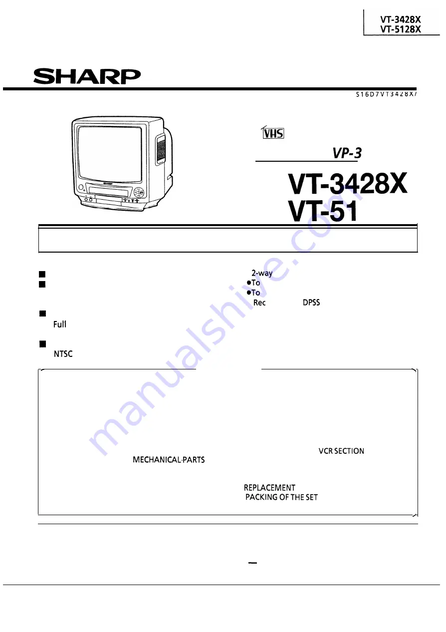
background image

SERVICE 

MANUAL

 TV/VCR COMBINATION

VIDEO TV

C h a s s i s   N o .  

MODELS

In the interests of user-safety (Required by safety regulations in some countries) the set should be
restored to its original condition and only parts identical to those specified should be used.

FEATURES

 TV/VCR Integration for Easy Operation
 Single Built-in Tuner for Simple Operation

Timer Programme Setting by the On-Screen

Display

 Auto Tracking Control

 Auto Head Cleaning System

On-screen Display with Menu Screen Guidance

 Wake-Up/Sleep Timer

 Simple Playback

 Child-Proof Lock

 Lock Operation Mode
 Lock the Power Off.

 Index with 

 (Digital Programme Search

System)

Full Auto Play Function

Auto Repeat Playback

Front input terminals Audio/Video

CONTENTS

Page

SPECIFICATIONS . . . . . . . . . . . . . . . . . . . . . . . .

2

IMPORTANT SERVICE NOTES . . . . . . . . . . . . .

3

. LOCATION OF USER’S CONTROL . . . . . . . . .

4

. DISASSEMBLY AND REASSEMBLY . . . . . . . .

6

. ADJUSTMENT OF THE TV ELECTRICAL .

CIRCUITRY . . . . . . . . . . . . . . . . . . . . . . . . . . . . .

8

. PRECAUTIONS IN REASSEMBLING . . . . . . .

15

. FUNCTION OF MAJOR 

16

. ADJUSTMENT, REPLACEMENTAND

ASSEMBLY OF MECHANICAL PARTS
ADJUSTMENT OF THE VCR ELECTRICAL.. ..

18

.

CIRCUITRY . . . . . . . . . . . . . . . . . . . . . . . . . . . .

42

. TROUBLESHOOTING . . . . . . . . . . . . . . . . . . .

45

Page

OVERALL SCHEMATIC DIAGRAM . . . . . . . .

57

CHASSIS LAYOUT OF TV SECTION . . . . . . .

59

. BLOCK DIAGRAM OF TV SECTION . . . . . . .

61

. DESCRIPTION OF TV SECTION

SCHEMATIC DIAGRAM . . . . . . . . . . . . . . . . .

65

. CHASSIS LAYOUT OF VCR SECTION . . . . . .

79

BLOCK DIAGRAM OF 

. . . . . .

81

. DESCRIPTION OF VCR SECTION

SCHEMATIC DIAGRAM . . . . . . . . . . . . . . . . .

91

. PRINTED WIRING BOARD ASSEMBLIES . . .

97

 PARTS LIST

. . . . . . . . . . . .

105

.

. . . . . . . . . . . . . . . . .

134

WARNING

The 

chassis in this receiver 

is partially hot. Use an isolation transformer between the line cord plug and

power receptacle, when servicing this chassis.

To prevent electric shock, do not remove cover. No user 
qualified service personnel.

serviceable parts inside. Refer servicing to

SHARP CORPORATION

Summary of Contents for VT-3428X

Page 1: ...TS Page l SPECIFICATIONS 2 l IMPORTANT SERVICE NOTES 3 LOCATION OF USER S CONTROL 4 DISASSEMBLY AND REASSEMBLY 6 ADJUSTMENT OF THE TV ELECTRICAL CIRCUITRY 8 PRECAUTIONS IN REASSEMBLING 15 FUNCTION OF MAJOR MECHANICALaPARTS 16 ADJUSTMENT REPLACEMENTAND ASSEMBLY OF MECHANICAL PARTS ADJUSTMENT OF THE VCR ELECTRICAL 18 CIRCUITRY 42 TROUBLESHOOTING 45 Page l OVERALL SCHEMATIC DIAGRAM 57 l CHASSIS LAYOU...

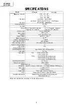
Page 2: ...I Video recording system 1 Two rotary heads helical scan I Number of Video Heads I 2 I Video signal PAL PlaybacWRecording Recording playing time 480 minutes max with E 240 tape Tape width 12 7 mm Tape speed PAL 23 39 mm set SP 11 70 mm set LP NTSC 33 35 mm set SP playback only 16 68 mm set LP playback only 11 12 mm set EP playback only Operating temperature 5 C to 40 C Storage temperature 20 C to ...

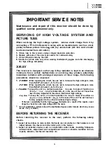
Page 3: ... the set VT 5128X When repairing the circuit be sure not to increase the high voltage to more than 29 3 kV at beam 0 4 for the set 2 m 3428X To keep the set in a normal operation be sure to make it function on 22 0 kV 1 5 kV 2 0 kv at beam 800 fi in the case of the set The set has been factory Adjusted to the above mentioned high voltage VT 5128X To keep the set in a normal operation be sure to ma...

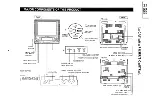
Page 4: ...d J FF Forward video search BUTTON STOP EJECT BUlTON REW Reverse video search BUTTON POWER WAKE UP TIMER INDICATOR VOLUME UP DOWN BUTTONS REC BUlTON CHANNEL UP DOWN BUl t ONS I f 4 AESRl REC VVOL A V CH A MAIN POWER SWITCH 01 _J VIDEO OUT JACK AUDIO OUT JACK ANTENNA IN TERMINAL VT 3428X MAIN POWER SWITCH 01 l AUDIO OUT JACK ANTENNA IN TERMINAL I 0 n 2 I 0 2 0 In c K 51c1 vi 1 0 z I 510 0 I ...

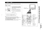
Page 5: ...WITH THE TIMER NOTES l Do not subject the remote control to impact water or excessive humidity l The remote control may not function if the photoreceptor window of this product is in direct sunlight or any other strong light If so move the product or alter the lighting l Incorrect use of batteries may cause them to leak or burst l Do not mix old and new batteries or mix the brands used l Both rech...

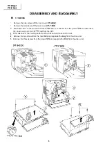
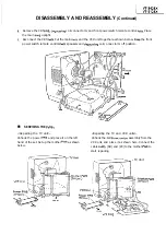
Page 6: ...nector from the main PWB and G connector from the power PWB and disconnect the anode cap and the CRT PWB unit from the CRT 3 After disconnect the coating earth from the CRT unit and take out the unit 4 Remove the two screws from the main PWB and separate the PWB from the video unit 5 Remove the three screws from the power PWB and separate the PWB from the video unit VT 3428X VT 51 28X 6 ...

Page 7: ... the front power switch remote control PWB speakers and degaussing coil connector G off position n SERVICING THE PWBs Repairing the TV unit Unhook the power PWB and place it on the left hand of the set Set up the mother PWB as shown below Repairing the TV and VCR units Unhook the PWB mechanism assembly from the VCR unit and place it as shown here Connect the cables AB AD and PC to the mother PWB t...

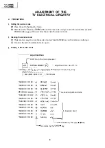
Page 8: ...et in the stand by mode again 3 Display in the service mode ROM No in the microprocessor Adjustment item Nos 01 l 2 L d L l data O 63 1 O 55 0 3 O 1 r i 1100 0100 0010 1101 I VCJICdata L SERVICE MODE 01 SERVICE MODE 02 SERVICE MODE 03 SERVICE MODE 04 SERVICE MODE 05 SERVICE MODE 06 SERVICE MODE 07 SERVICE MODE 08 SERVICE MODE 09 SERVICE MODE 10 SERVICE MODE 11 SERVICE MODE 12 T RED INT O 63 GRN IN...

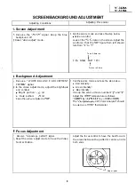
Page 9: ...t the brightness and contrast 8 Bright portion 120 nit l Dark portion 20 nit Keep the colour adjusted at 00 3 Focus Adjustment 1 Receive monoscope pattern signal 2 Reset the video adjust mode to have the Video Normal Position To be 0 here too f To turn to 0 here 1 Call the service mode and take the step below l Red intensity l Green intensity l Blue intensity Pick up the service mode numbers 2 and...

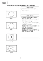
Page 10: ...lect the service mode number 4 Adjust the VERT AMP to have 10 overscan l VERT LIN vertical linearity Select the service mode number 5 Adjust the VERT LIN to have optimum vertical linearity See Figs 1 and 1 l VERT POS vertical center Select the service mode number 6 Adjust the VERT POS so that the vertical center be at the center of the screen See Fig 3 l HOR PHAS horizontal center Select the servi...

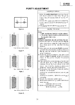
Page 11: ...ep the set facing the east 1 Observe the spots a and b shown in Fig A with a microscope Adjust the purity magnet to have these spots at the specified landing positions 2 If the right and left spots are dqually deviated outwards from their landing positions shown in Fig B push the deflection yoke forwards for proper positioning 3 If both the spots are shifted to the right or left shown in Figs C an...

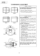
Page 12: ...e following steps for dynamic convergence at the edges of the CRT screen l Convergence in Fig a Insert the wedge a in position and tilt the deflection coil upward for correct convergence l Convergence in Fig b Insert the wedges b and c in position and tilt he deflection coil downward for correct convergence l Convergence in Fig c Insert the wedge c deeper and tilt the deflection coil rightward for...

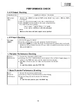
Page 13: ...ia the A V front jacks 3 Using the CH Am key call the AV mode and make sure the external video and audio signals are being properly received The AV mode is available somewhere between lch and 40 max ch f 3 Protector Performance Checking Protector Performance 1 Receive the monoscope pattern signal 2 Apply 20V from the constant voltage power supply to the cathode of D607 TP603 no symbol on the PWB a...

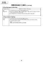
Page 14: ...on With any signal input make sure the background is blue Make sure also that the audio is mute 3 Turn off the function and make sure the blue background disappears c 6 Record Index Checking Record index 1 In the SET UP mode select the REC INDEX function 2 Turn on the function to make recording Make sure the clock has been preset 3 Check the recorded contents Note Make sure the channel and time ar...

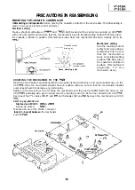
Page 15: ...e that the mechanism is back to its initial setting position l Now place the cassette controller in position This method is applicable f o r t h e mechanism alone COUPLING THE MECHANISM TO THE PWB Match the mechanism s projections with the two symbols round reference and oval sub reference on the VCR PWB Place the mechanism straight down in position with due care so that the mechanism chassis s ou...

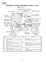
Page 16: ...pe drive train height with the upper and lower guides 3 7 Tension arm ass y Detects the tension of tape while running and brakes the supply reel disk via the tension band Main supply brake lever Brakes the supply reel disk to prevent tape slackening when the unit is stopped in fast forward or rewind mode 16 Pinch roller lever ass y Press fits tape to the capstan during tape running The right protr...

Page 17: ...r of the capstan D D motor to the the master cam in the slow still mode and brakes it to a reel disk via the reel idler certain degree 3 Capstan D D motor A motive power which runs the tape It transmits the power via the reel belt 8 Shifter Transmits the operation of the master cam to break and loading gear 4 Reel belt Transmits the power to run the tape to the reel pulley 9 Take up loading gear S...

Page 18: ...X Gauge Head Cassette Torque Meter acD JiGTH0006 AW f 3 JiGVHT 063 CZ Tension Gauge 3009 Tension Gauge 2 0kg JiGSG0300 BF JiGSG2000 BS Hex Wrench 0 9mm I 1 I JiGHW0009 AE Hex Wrench 1 2mm Hex Wrench 1 5mm JiGHWOOl2 AE JiGHWO015 AE Alignment Tape PAL Alignment Tape PAL VROCPSV VROUBZFS Tension Gauge Adapter JiGADP003 BK 1 Remarks These Jigs are used for checking and adjusting the reel disk height T...

Page 19: ...0 CB made parts the specified torque is 5 kg This Jig is used for height adjust JiGDRiVER 1 O 7 AS ment of the A C head and X position Box Driver JiGDRiVER 10 4 AV This Jig is used for replacement of 15 the SI roller C JiGDRiVER lo 55 A R This Jig is used for height adjust ment of the reverse guide 17 Reverse Guide Height JiGRVGH F18 BU This Jig is used for height adjust Adjusting Jig ment of the ...

Page 20: ...lcohol cl cl cl cl Clean tape contact part cl cl cl El with the specified cleaning liquid cl q cl 0 Poor S N ratio no colour El 0 Cl 0 Cl 0 Cl Poor flatness of the envelope with alignment tape Clean tape contact area q q 0 0 Poor colour beating with the specified cleaning liquid Cl 0 cl 0 Sound too small or distorted cl q 0 0 No tape running uneven colour cl q cl 0 No tape running tape slack Clean...

Page 21: ...assette control drive gear Figure l 2 l Drive angle of cassette control 2 Follow the procedures for removal in the reverse order Notes 0 In using a magnet screw driver be sure to keep it away from the A C head FE Full Erase head or the drum Q In removal and reassembly take care not to hit the cassette housing control assembly or tools against the guide pin drum or the like thereabout 0 Load the ca...

Page 22: ... Replace the tension band around the supply reel disk and insert it to the hole of the tension arm 4 Check the reel disk height and reassemble the supply main brake Notes Take enough care not to deform the tension band during installation of the supply reel disk Be careful not to damage the supply main brake l Reassembly Take up reel disk 1 Clean the reel disk shaft and apply oil to it 2 Install a...

Page 23: ...gher than 69 mN m 700 gfcm 69mN m 700gf cm or more guage is held at 1 its maximum value Red mark 3 Take up direction Figure l 8 l Adjustment 1 If the take up torque is outside the range clean the capstan D D motor pulley reel belt and reel pulley with cleaning liquid then recheck the torque 2 If the take up torque is still out of range replace the reel belt Notes 1 Hold down the torque gauge so th...

Page 24: ...y Use the center of the fluctuation as the value Place the ass y in the SP record mode and check that the take up torque is within the range Adjustment the take up torque in the playback mode is outside the range replace the reel pulley ass y Note Stabilize the cassette torque meter to prevent floating CHECKING AND ADJUSTMENT OF TAKE UP TORQUE IN VIDEO SEARCH REVERSE MODE l Remove the cassette hou...

Page 25: ...ion every 2 to 3 seconds and check that the torque is I 3 2 0 8mNem I 3 8 gfcm Note Set the torque gauge securely on the take up reel disk If it is not secure the measurement will be incorrect QMeasure the torque with the torque gauge s weight exerted on the reel disk CHECKING THE VIDEO SEARCH REVERSE BACK TENSION Remove the cassette housing control assembly Make a short circuit between TP8804 and...

Page 26: ...the cassette tape 4 Make the adjustment with the beginning of a E l 80 tape l Checking Figure l 16 1 Set a cassette tape press the REC button and get the tape loaded Now check the tension pole position 2 Visually check to see if the left end of the tension pole is in alignment with the line 0 2mm left of the center line of the SI roller Readjust as required in the following steps Tension pole fw I...

Page 27: ...l Remove the cassette housing control assembly l Make a short circuit between TP8804 and TP8805 both located at the center on your side on the VCR PWB with a 22 ohm resistor NOW turn on the power l Setting 1 Open the lid of the cassette torque meter and hold it with two pieces of vinyl tapes 2 Load the cassette torque meter into the unit 3 Put the weight 5009 on the cassette torque meter w Figure ...

Page 28: ... 25 l Remove the cassette housing control assembly l Make a short circuit between TP8804 and TP8805 both located at the center on your side on the VCR PWB with a 22 ohm resistor Now turn on the power 0 Setting 1 Set a torque gauge to zero on the scale Place it on the take up reel disk 2 Switch from the FF mode to the STOP mode 3 Disconnect the AC power plug l Checking 1 Slowly rotate the torque ga...

Page 29: ...s not fly 1 off when removing the A C head screw A C head PCB Pay attention to Figure l 26 l Replacement 1 Solder the removed A C head PWB onto a new AK head assembly 2 The A C head assembly is attached so that the A C head arm and A C head plate are roughly parallel to each other New A C head Never touch the PCB VT 3428X VT 51 28X adjusting nut Figure l 28 l Adjustment A C head tilt angle 1 Set t...

Page 30: ...o that the control head is visible 0 3 to 0 5mm below the bottom of the tape Height adjustment of reverse guide Reverse guide height adjusti g jig guide Reverse guide height adjusting jig 4 fGo end is 13 52 mm Not go end is 13 38 mm a Figure l 33 W 1 2 3 4 Remove open lever Figure l 34 a In the tape load mode make adjustment at the 13 38mm side first and then rotate the height adjusting nut by l 6...

Page 31: ... tape to prevent floating of the cassette tape Guide roller Figure l 35 Figure l 36 d In the X value adjustment mode see the Electrical Adjustment change the envelope waveform from MAX to MIN and MIN to MAX by pushing the or tracking button and check a flat response is obtained on the waveform e If a flat response cannot be obtained roughly adjust the guide rollers on the supply side and take up s...

Page 32: ... the tape drive train alignment tape Push the or button to change the envelope waveform from MAX to MIN and MIN to MAX Adjust the guide roller s height on the supply and take up sides with an adjusting screw driver to obtain an envelop waveform that is as flat as possible If the tape is above or below the helical lead the PB CHROMA waveform will take the shape shown in Figure l 43 Adjust for maxim...

Page 33: ...lt 0 Remove the screws Figure l 45 Figure l 46 l Reassembly 1 Mount the capstan motor on the mechanism chassis making sure not to allow the capstan shaft to hit the mechanism chassis and attach it with the three screws 2 Attach the reel belt Reconnect to the board to board connector on the VCR PWB Notes 1 After installing the capstan D D motor be sure to rotate the capstan D D motor and check the ...

Page 34: ...ack of the mechanism chassis 1 Assembling the pinch roller assembly and the pinch drive cam on the front of the mechanism chassis Place the following parts in position in numerical order 1 Pinch drive cam 2 Pinch roller and pinch double action lever 3 Open lever 0 Insert Pinch Drive Cam Fit the point of the pinch drive cam to the fourth tooth of the pinch drive lever and insert the pinch drive cam...

Page 35: ...Q Insert Pinch Roller Pinch Double Action Lever Ass y Pinch Roller Pinch Double Phase Matting Point Action Lever Ass y Figure l 48 2 VT 3428X VT 5128X 0 Insert Open Lever Figure l 48 3 35 ...

Page 36: ...t the point 0 as shown below 2 Place the shifter in position keeping in mind the CD insertion points and the 6 relief points 3 For the phase matching at the insertion point 0 see the point 0 as shown below 4 Finally fix the shifter with two washers located on insert points 0 and 6 Phase Matching Point 0 Insert Point o Cut Washer LX WZ1041GEOO L Insert Y Point I i czb Insert Point A I I Point Eh Fi...

Page 37: ...the point as shown below 2 Place the master cam in the position as shown 1iE ft Note See the figure below for the phase matching between the master cam and the cassette control drive gear 3 Finally fix the master cam with E ring below E ring XRESJ40 06000 Master Cam I Master Cam ette Housing Drive Figure l 51 ...

Page 38: ...m chassis Catch the spring to the take up fixing guide that is at the left of the A C head Slow Brake A 0 Kfing Motor Figure l 52 Note Before setting up the loading motor make sure the phase is matched To do so turn the connection gear clockwise and check to see if the loading is complete and if the pinch roller comes into contact When these actions are made smoothly return the mechanism to the st...

Page 39: ... motor as shown above Figure l 53 Figure l 54 Q Adjust the worm gear s thrust gap to 0 05 to 0 3 mm Use the specific washers for an appropriate thichkness 1 13 0 O lmm 1 To press the motor in receive it by portion A Figure l 55 Press fit the loading motor pulley with a force of less than 98N 10 kgf Be sure that the pulley is 13 0 0 05 mm away from the motor 39 ...

Page 40: ...BLY OF CASSETTE HOUSING 0 Drive Gear R and Drive Angle Ass y MSPRT0381 AJFJ Apply grease Phase Matching Point l Fix the drive angle ass y to the drive gear Ras shown in the figure Drive angle ass y Drive gear R Figure l 56 40 ...

Page 41: ...lign the drive gear s round hole with the synchro gear s triangular A symbol Do this alignment for both the drive gears Phase Matching Point Figure I 58 Note Do not over turn both of the drive gears when the phase has been matched These gears are partially toothless and might come out of mesh with the synchro gear rematching In such a case the phase needs 41 ...

Page 42: ...the STAND BY POWER button while the CH A button on the front panel is being pressed down more than 3 seconds 2 Play the alignment tape VROCPSV and press the PROG button on the remote control to set the tracking to center TEST is displayed on the screen it means tracking is in center in the playback mode See Note below 3 Connect a dual trace oscilloscope to the test points TP2208 Video out and TP22...

Page 43: ...ill mode 2 Using the CH Am TR e e buttons on the remote control make adjustment so that the vertical jitter becomes minimum 3 Now press the STOP button to stop the tape 2 Using the CH Am TR e e buttons on the remote control make adjustment so that jitter becomes minimum 3 Now press the STOP button to stop the tape Adjustment of NTSC System EP still picture vertical jitter Measuring instrument Moni...

Page 44: ...V input mode 3 Make the self recording and playback the recorded portion of the tape 4 Make sure that the Audio Out level is as specified If it is out of specified value verify the bias current Adjustment of audio bias current below Adjustment of audio bias current Measu ri ng instrument AC milli voltmeter or Osci I loscope Mode I Record Input signal I Not required Test point I TP6601 TP6602 Contr...

Page 45: ...TING FLOW CHART NO 11 A cassette tape Is not taken in Is the cassette housing distored 1 YES Fix or replace the cassette housing I NO 1 1 I Does the start sensor cover NO become open when the cassette Check the start sensor cover tape is inserted 7 JYES I 1 I I 1 Does the start sensor pin 86 of IC8801 go to L level when the cassette tape is inserted 7 NO Check the start sensor and the way up to pi...

Page 46: ...eck between pin 6 of lC8803 and all the way up to pin 7 of J IC8801 1 YES Is about 11V at pin 10 of lC8803 1 NO p r C8803 and L level of pin Is the correct voltage at the loading motor terminal 1 NO p Check between lC8803 and all the way up to the loading motor Does the loading motor run 7 NO ____ Replace the loading motor 1 YES FLOW CHART NO 1 5 No power 1 1 YES Check IClOOl and lC8801 I Does pow...

Page 47: ... 99 of I 1 YES 1 I I N O Check the ATl2V line I I I YES I Check replace the capstan sensor pulse appears Insert the cassette and pu e unit in FF or REW I Are there the take up sup the col ectors of P ly reel pulses at YES Checkall thewa u to Q8802lQ880 1 y 31 and 59rp 0 NO Are there the take up sup the col ectors of P ly reel pulses at YES Check between D8804 and Q8802 between D8804 D8803 D8803 an...

Page 48: ...E connector and IC770 1 and between the ME socket and pin 62 of IC8801 IS 12V at pin 4 of ME connector _ No w Check the ATl2V line YES I 1 I Check replace the drum motor I FLOW CHART NO l 10 I The drum motor runsonly for a few seconds I I Is drum PC signal at pin 5 of NO ME connector 7 Check the drum motor Is drum PC signal at pin 66 of IC8801 YES Check between the ME connector t8 l l the way up t...

Page 49: ...witching pulse at pin NO See FLOW CHART NO 18 Check the composite IC8801 13 of IC8801 cl sync signal at pin 25 of IC2201 and 42215 NO YES Check pin 3 of the Is there the drum l connector ME and the control output at pin drum motor 4 of IC8801 NO w Replace IC8801 YES zF mk ge signal Ii ne of v Is there the drum Does the drum error control voltage applied NO amplifier circuit of 1 7701 NO topin l of...

Page 50: ... 68 of IC8801 77 of ICI8801 I No i YES Is there capstan control signal at pin N O Replace IC8801 3 of IC8801 I I J Does PB CTL signal appear at pins 71 and YES 72 of IC8801 1 NO Does CFL amplifier circuit of IC8801 pins 73 to 79 operate normally Does the noise appear at pin 73 when touch R7737 by hand J YES Are pins S 6 and 7 of IC7701 normal Replace IC770 1 Check the composite sync signal line be...

Page 51: ...e way up to pin 52 of IC2201 I 1 YES 1 IS pin 2 of 1 33019V level 1 YES NO Check the BIAS CTL 9V line VCR RECORDING MODE CHROMA TROUBLESHOOTlNG Record Is In black and white E E colour mode FLOW CHART NO 1 14 I 7 Are there YIC data and clock signals at pins 14 and 15 of lC2201 NO Check data and clock repectively when signals from IC8801 recording starts YES f Is there a signal at pin 2 No lsthere 5...

Page 52: ... IC330 1 Check the H SW pulse line YES I I I Check EH connector I I I I I 4 NO GOOD NOGOOD Check video head and or replace IC3301 I I I AYES I Check peripheral circuit of2 47 and 48 of I Check pin 33 of IC2201 NeG JOD Replace IC2201 I t is there a sim No Check theiignal line all the way up of IC2201 topin l5 of IC3301 I I 1 1 1 YES Is there a signal at pin 56 No of IC2201 Check IC2202 I I I I I YE...

Page 53: ...l at pin 6 and NO pin 5 of T6601 Bias Oscillator h Is there an Audio Signal at pin 14 of YES IC6601 7 t Is there an Audio Signal at pin 14 of lC6601 7 ES line between pin 18 of IC6601 and Audio I I YES i NO 1 YES i YES Check the H level at pin 22 of IC6601 in i YES ICheck 46606 and the EE L line I Check the L level at pin 22 of IC6601 in PB mode I Replace IC2201 I t Replace IC6601 If Check the sig...

Page 54: ...circuit in the key input 1 YES NO Check IClOOl iX2604CE and switches for poor soldering Are signals received at pins 1 2 I NO and 16 IClOOl when the key is Check key lines to input of IClOOl activated 7 4 YES I Check IClOOl IC8801 and signal line of serial datas serial clock and ready L INFRARED WC TROUBLESHOOTlNG FLOW CHART NO 2 3 I No operation is possible from the infrared remote control I I Do...

Page 55: ...oes the noise level increase at max Contrast Brightness and Sound Control h noise increases but no signal is received I Is there a signal at pin 8 ND Is there a signal at pin ND of IC402 8 of IC403 YES Check IC402 and adjacent parts j adjacent parts Check Tuner AGC IL _ 1 L J Is there a ND signal at P m 8 of C302 A YES I Check IClOOl ___ 1 r r i 1 Check the IF 1 Pack r r Check thePC9V r I I line I...

Page 56: ...ker I I _ ___ _ ___1 I i i I NO PLAYBACK PICTURE FLOW CHART NO 2 6 I NO PLAYBACK SOUND ICheck the TV TROUBLE SHOOTING NO SOUND I FLOW CHART N0 2 9 Circuits to be checked 0 IC 801 and its Adjacent Circuit 0 R G 8 Output Ctrcuit FLOW CHART NO 2 10 IC801 X801 PAL 17 7MHz I a r YES Is the white balance properly adjusted IN0 r y j Readjust the white balance I I I L l r I I Check 4852 and its 1 1 adjace...

Page 57: ...747FP DRUM MOTOR DRIVER MOTP I I24GE OCGlO704 5 c4ulcoNlRoL ORW MOTOR 00 MA4 FO B AT IZV DRu PQ DRWFopQW AT sv ________________________ VIDEO HEAD HEDVO I76GE FULL ERASE HEAD AUDIO CONTROL HEAD HEDUOO63GE LOADING MOTOR h4DTM I 062GE MOTN205 I GE NW 027 IAJ Awxo ERAOE nxo AwIoa7AsElao H w10 a40 mxl AWIO n3ll m ClLlEAD ClLtEM 1 I 2 1 3 I 4 I 5 I 6 57 ...

Page 58: ...I I I I I I I I I I I I I 1 I I I I I I I I I I I I I I I I I I I I I I I ___ ___________ v FDQIS I X t i 1 I DEFLECTION YOKE DY60 I CILHOOS PENJ X CILH l576CE CNW I669PE t CNW I 894PE iSCRIPT WITH IONS I 7 I 8 I 9 I 10 I 11 I 12 I 58 ...

Page 59: ... 0PC cl755 c l Q706 0Q757 El In 4754 O BN 0 QlOOl 1 X801 I 0 9 IC803 IC802 4756 hl BN BN BK IC752 IC754 430 0 1 4302 1 I IC301 I C302 t I 1 III 1 0 0Q4u 1 L601 t I IC401 n L602 UNT20 1 I F P1 I C402 4403 4402 00 0 4404 Q501 0 0 4502 0 4306 T 0 4303 0 Q204 0 Q604 540 1 VIDEO AUDIO OUT OUT PWB B IO C762 lC702 T701 n I 1 I 2 I 3 I 4 I 5 I 6 59 ...

Page 60: ... 01r 5 4201 4202 U PR701 0 P PWB C Q856 Q855 0 Q852 0 60 8854 0 0 Q851 001 PWB F PWB D t Y lB4 s1201 I_ P O W E R ALIM cl t g P AY s l 204STOP EJECT cl cla e s1202 S1203 REW aam c l P1202 S1205 I 7 I 8 I 9 I 10 I 11 I 12 I 60 ...

Page 61: ...VT 3428X W 51 28X BLOCK DIAGRAM OF TV SECTION h ICI002 moM 0759 VT REG v SYNC H SYNC H DRIVE IC803 R Y B Y AMP I ID602 7 I II I D603 9604 mOTECT t TECT H SYNC H FLY IN iFa I I 1 I 2 I 3 I 4 I 5 I 6 f 61 I ...

Page 62: ...i T 3428X VT 5128X IC35I AUDIO AMP 0401 VIDEO AMP IVE T 030 I AUDIO AMP IC40I VIDEO SW MT20 I IF PACK I tt 020 I 0202 0203 I I our can J 7 I 8 I 9 I 10 I 11 I 12 I 62 ...

Page 63: ...ECTION 085 I eO852 0853 VIDEO OUTPUT 0854 0855 0856 CUT OFF POWER I I PWB 8 I 0753 e ERROR I I c DETECT I I 0751 RELAY SW 0752 ON OFF DELEY 0761 SW ON OFF I IC702 PHOTO COUPLER I I T70 I POWER TR m 1 I 2 I 3 I 4 I 5 I 6 63 ...

Page 64: ... CONTROL I I I OSC I MUVER LATM 7mOER rl qgg 0 F START l L 1 YS t l 070I ERROR AMP 0702 0703 LATCH D705 IC70I I or04 OVP L I I D706 D70 l 4 RECTIFIER I I L702 L799 ygE I Al 1 I I I I I I I I I I I I I I I I I I I I I I I m w m m I I J I 7 I 8 I 9 I 10 I 11 I 12 I 64 ...

Page 65: ...N ISOLATING TRANSFORMER BETWEEN TV RECEIVER AC LINE TO ELIMiNATE HAZARD OF ELECTRICSHOCK CAUTION This circuit diagram is original one therefore there may be a slight difference from yours NOTES 7 The unit of resistance ohm N is omitted K 1000 ohms M 1 Meg ohm 2 All resistors are l 8 watt unless otherwise noted 3 The unit of capacitance F is omitted 1 puF P J 4 The values in parentheses are the one...

Page 66: ...04CE ix1 566BM 1 8 iX1495BM 2SK304CD 2x3198 2SA1271 2SAl266 2SC3279N 2SC383 2SA988 2sc2229 2SA1321 or 2SA1371 2SC227 1 STRM6523 f 1J vvvvvvvu TA7812S TA7805S SE1 15N R 1L L BASE COLLECTOR EMllTER 2sc3399 DTC144ES Ill l Ill i 1 9 TDA7056A 0 0 0 II M II B C E 2SD1877 2502095 l 7 ix1 163BM 2SD1944 1 9 TA7348P WT 33 66 ...

Page 67: ...C 3 2 V 0 6 AC 1 9 Vp p 0 7 AC 2 2 Vp p 0 8 AC 1 7 Vp p DC lS5V DC OV DC 2 4 V 0 4 AC 1 7Vp p 0 5 AC 1 7 Vp p DC 1 55 V DC 1 55 V 0 9 AC 50 Vp p DC 52V 0 11 AC 950 Vp p DC OV I I I I I I I I I 0 12 AC 6 2 Vp p DC OV 013 AC 71 Vp p 014 AC 71 Vp p 015 AC 8OVp p DC 128V DC 128V DC 128V 67 ...

Page 68: ...VT 3428X VT 5128X 0 1 AC 0 9 Vp p I 0 2 A C 1 3Vp p DC 5 0 V DC 3 2 V WAVEFORMS VT 51 28X 0 7 AC 2 2 Vp p DC OV I I I I I I I I I 0 11 AC 950 Vp p DC OV ...

Page 69: ...VT 3428X VT 51 28X MODEL VT 3428X SCHEMATIC DIAGRAM Mother Unit T O PWB E EE I I Rlun I I I 4hM o1003 I 2SC3 I984 I 25Cl815 1 0404 2X3198 G l2SC I B 15 C 1 I 2 I 3 I 4 I 5 I 6 69 ...

Page 70: ...M 3428X VT 5128X 1c35 1 TDA7056A 1 II TO PWB E Eli 2SC3 198 G 2SC 18 I G I I I I ii i I I 0302 TP1001 70 ...

Page 71: ...H G F E D C B A MODEL VT 3428X SCHEMATIC DIAGRAM CRT Socket Powe i I2 CR T O PWB A M O T O R M UR 20 CR No B I T O PWB A POWER 3 I I I I I 1 I 2 I 3 I I 4 I 5 I 6 c 71 ...

Page 72: ...IT OF RESISTOR OHM IS OMITTED tK IO00 OHMS M MEGAOHMI 2 ALL RESISTORS ARE I BWATT UNLESS OTHERWISE NOTED 1 3 ALL CAPACITORS ARE JJF UNLESS OTHERWISE NOTED P uuFl TO PWB A T O PWB A IPEZZ I b 7 NC 8 o p m W o 7 I m m _ J 8 I 9 I 10 I 11 I 12 1 72 ...

Page 73: ...X SCHEMATIC DIAGRAM Mother Unit T O PWB E EE H G F E D C B A IC I002 IX2448CENI EEPROM TO PWB 0 iii PWB c 04 r 0403 0402 2SAl266 Y 2SC3198 l2SA1015 Yl lZSC1815 0404 2X3198 G 25C I6 15 G I t h I 2 I 3 I 4 I 5 I 6 73 ...

Page 74: ...IC35 1 TDA7056A 1 IL TP1001 EXT YYNTRot Gm so1 TO PWB E IEII I o I WT OIIT I 7 I 8 I 9 I 10 I 11 I 12 I 74 ...

Page 75: ...MODEL VT 51 28X SCHEMATIC DIAGRAM CRT Socket Powe TO PWB A TO PWB A T O PWB A F POWER P 075 I I 1 I 2 I 3 I 4 I 5 I 6 c 75 ...

Page 76: ...ISTOR OHM IS OMITTED K IO00 OHMS M MEGAOHMl 2 ALL RtSISTORS ARE I BWATT UNLESS OTHERWISE NOTED 3 ALL CAPACITORS ARE PF UNLESS OTHERWISE NOTED P uJJF VCR KEY PWB I202 OPWBFB735PEi TO PWB A T O PWB A m m PWB70 I OPWBFB732PEZZ LTSS A I cILGo36aE 02 1207cE 76 ...

Page 77: ...W 3428X VT 51 28X 5 55 5 ii 2 5 z i f5555 T 5 oe Bu 0 e TUN o AGC o BL o BH j VTSS8S2D Infrared Remote Control Unit RRMCGI 176PESA 1 1 I 2 I 3 I 4 I 5 I 6 1 77 ...

Page 78: ...m 3428X VT 51 28X IF Pack Unit RiWOOl7CEZZ 1 4 11 l e i t 1 I 2 I 3 I 4 I 5 I 6 1 78 ...

Page 79: ...OUT OF VCR SECTION PWB E TP2208 VIDEO OUT 0 EE IIEG EB TP2203 PB CHROMA TP2204 H SW P TP2205 GND i I IC3301 _ _ __I 0 Q2214 c l Cl2215 08804 c220 I E N D S E N S O R I i J I I I X5502 S U REEL S E N S O R D8803 79 ...

Page 80: ...SOR C A M S W A IC8803 cl IC8802 HEAD SWITCHING 08804 T V REEL SENSOR AGGI PG ij 0991 I IC990 I I cl ED S8204 S8206 UP UP S8203 I S8205 I gzD a 3 pJ II I s VOL I I CH 2 VOLUM VOLUME CANALE CANALE v A v A C i VEGl 0830 I D8302 08303 09913 POWER REC L E D TIMER D8304 u WAKE VP REGI CHILD LOCK I TP8804 N O N TP8805 CAS CON 7 I 8 I 9 I 10 I 11 I 12 1 80 ...

Page 81: ...DIAGRAM OF VCR SECTION 4 OVERALL BLOCK DIAGRAM IC402 VIDEO SELECT SW Tu ER WMTUER A0 8 h L 5 lvcs IEC DEKmuAloR IAllx L I i V I D E O s1ouAL _ DUFUY PROESS a M VmEo DFVT 3 ux mDEo 3 a M Auom m I 10 a 1 I 2 I 3 I 4 I 5 I 6 81 ...

Page 82: ...VT 3428X VT 5128X I AWIO m I Au 10 f X I 7 I 8 I 9 I 10 I 11 I 12 I 82 ...

Page 83: ...W 3428X VT 51 28X BLOCK DIAGRAM OF VCR SECTION H SERVO PROCESS BLOCK DIAGRAM r d I I I I I I I I _ _ __________I 1 I 2 I 3 I 4 I 5 I 6 83 ...

Page 84: ...VT 3428X VT 51 28X I 0 ___ __ ___ 10 0 1 rl i CAPSTIH UDTOR UllT I ____ _ __ ___ I 7 I 8 I 9 I 10 I 11 I 12 1 84 ...

Page 85: ...VT 3428X VT 51 28X BLOCK DIAGRAM OF VCR SECTION m SYSTEM CONTROL BLOCK DIAGRAM c A 4 ij B f t t 1 I 2 I 3 I 4 I 5 I 6 85 ...

Page 86: ...VT 3428X VT 5128X I n SAFETY DEVICE BLOCK DIAGRAM 4L me A rdl a I 8 rie fI I 7 I 8 I 9 I 10 I 11 I 12 I ...

Page 87: ... I u c D I ea I n I u I m I n I GI I I I AU 10 PROCESS PC 4 CC BIAS QEN LP zi a v m SPaJ cn 9v FULL IDAY M A D AU010 ERASE M A O All010 HEA0 0 z ...

Page 88: ...ER 6 FROM CAPSTAN MOTOR mLIc7702 JlJJ 4 2v t e1 FROM CTL HEAD MH EF 2 CTL MH EF I CTL SYSTEM CONTROLLER XC8801 1 25 or 3OHr I PS CTL AMP b 4 PB ON MANUAL SYSTEM IS 0Y TV DATA FROM TRANSFERED TV AUTO SYSTEM IS TRANSFERED BY SYS CON DATA TO TV SIG 6OHz 5v GENERATOR 08815 SIG SOHz LPfHl MESECAM H TO VIDEO AUDIO BLOCK AUTO SYSTEM SELECT ...

Page 89: ... H G F E D C B A BLOCK DIAGRAM OF VCR SECTION 4 VIDEO SIGNAL FLOW BLOCK DIAGRAM I I Aw 1 1 0 LIN Qy I 1 I 1 I 2 I 3 I 4 I 5 I 6 89 ...

Page 90: ...VT 3428X VT 51 28X I t 7 I 8 I 9 I 10 I 11 I 12 I ...

Page 91: ...d pF p ppF 4 The values in parentheses are the ones in the PB mode the values without parentheses are the ones in the REC mode VOLTAGE MEASUREMENT CONDITIONS 1 DC voltages are measured between points indicated and chassis ground by VTVM with AC220 240V 50Hz supplied to unit and all controls are set to normal viewing picture unless otherwise noted 2 Voltages are measured with 1OOOOpV B W or colour ...

Page 92: ... P In 26 ofIC2201 TP2203 P In 18 olIC3301 Headmltohlng pulse v 6 ovp p p In t66 ofIC8601 v 4 4vp p COMPOSITE SYNC PS CHROMA REC Pin 18 of IC3301 p In 3Wot I08801 REWPB P In 67 ot ICB801 REC PB REC PB CLOCK DRUM P O REC PB D R U M FQ SERVO SERVO SERVO AUDIO AUDIO A U D I O A U D I O nrvl z G2v 4 w 4A H 76OHz SP H 70 rSkHz I i IkHz H IkHz ti 70tSkHz V ZSVp p v zwp p V A8Vp p V 28mVma V LbVp p v 13vp...

Page 93: ...I VT 3428X VT 51 28X H G F E D C B A SCHEMATIC DIAGRAM VCR Unit l TPPOI Lo343oE E FizEz I 3 Y D m FP TO SYSTEM CONTROL SERVOWCRI I 1 I 2 I 3 I 4 I 5 I 6 93 ...

Page 94: ...VT 3428X W 5128X 3 7 I 8 I 9 I 10 I 11 I 12 I 94 ...

Page 95: ...8X VT 51 28X SCHEMATIC DIAGRAM VCR Unit 2 PWB E F5 I67AJ J 1 J L O A D I N G M O T O R 1 1 j VOLTAGE SW 1 w3 mAwo1 XmXI w T DlEn REC L E D TIMER CHILD LOI DRIVE LED DRIVE L E O DRIVl 1 I 2 I 3 I 4 I 5 I 6 95 ...

Page 96: ...VT 3428X VT 51 28X TO Y C AUDIO CIRCUIT NCR 21 I I I I 7 I 8 I 9 I 10 I 11 I 12 I 96 ...

Page 97: ...1 H G F 8 W 3428X VT 51 28X PRINTED WIRING BOARD ASSEMBLIES H TV SECTION PWB A Mother Unit Wiring Side 1 I 2 I 3 I 4 I 5 I 6 I 97 ...

Page 98: ...VT 3428X VT 51 28X _ x I 1 PWB D Power SW R C Unit Wiring Side PWB F VCR Key Unit Wiring Side 7 I 8 I 9 I 10 I 11 I 12 I 98 ...

Page 99: ...VT 3428X VT 51 28X 7 H G F E D C B A W TV SECTION PWB B Power Unit Wiring Side 1 I 2 I 3 I 4 I 5 I 6 99 1 _ 7 PWB C CRT Socket Unil ...

Page 100: ...m 3428X VT 51 28X Wiring Side f r 7 I 8 I 9 I 10 I 11 I 12 1 100 ...

Page 101: ...n n VCR SECTION H G F E D C B A VT 3428X VT 51 28X 1 lclinch PWB E VCR Unit Wiring Side I i 1 I 2 I 3 I 4 I 5 I 6 101 ...

Page 102: ...VT 3428X VT 51 28X I 7 I 8 I 9 I 10 I 11 102 1 12 I ...

Page 103: ...VT 3428X VT 51 28X n l VCR SECTION PWB E VCR Unit Chip Parts Side I i 1 I 2 I 3 I 4 I 5 I 6 c 103 ...

Page 104: ...VT 3428X I m 5128X 1 7 I 8 I 9 I 10 I 11 I 12 I ...

Page 105: ... PWB A DUNTK8946WEV2 Main Unit PWB B DUNTK8732WEV4 Power Unit PWB C DUNTK8733WEV4 CRT Socket Unit PWB D DUNTK8734WEV4 Power Switch R C Unit PWB F DUNTK8735WEV4 VCR Key Unit VCR Section PWB E DUNTK5167TEV5 V C R U n i t MODEL VT 5128X TV Section PWB A DUNTK8946WEV3 Main Unit PWB B DUNTK8732WEV6 Power Unit PWB C DUNTK8733WEV6 CRT Socket Unit PWB D DUNTK8734WEV6 Power Switch R C Unit PWB F DUNTK8735W...

Page 106: ... AA AA AA AA AA AC AD AA AA AA AA AB AB AB AB AB AD AB Ref No Part No Description Code D604 VHDlSSllS lE R Diode lSSl19 AA D605 VHDlSSllSNlE R Diode lSS119 AA D606 RH DX0302CEZZ R D i o d e AC D607 RH EX0340CEZZ R Zener Diode AB D608 VHDlSSllS lE R Diode lSS119 AA D609 VHDlSSllSNlE R Diode lSS119 AA D611 VHDlSSllS lE R Diode lSS119 AA D612 VHDlSSllS l E R Diode lSS119 AA D613 VHDlSSllS lE R Diode ...

Page 107: ... R 1000 50V C e r a m i c AA C356 VCKYPAl HB102K R 1000 50V C e r a m i c AA C357 VCEAGAl HW106M R 10 5OV Electrolytic AC c401 VCEAGAlCW476M R 47 16V Electrolytic AB C402 VCKYPAl HB102K R 1000 50V C e r a m i c AA C403 VCEAGAlCW476M R 47 16V Electrolytic AB C404 VCEAGAlCW476M R 47 16V Electrolytic AB C405 VCEAGAlCW476M R 47 16V Electrolytic AB C406 VCEAGAlCW476M R 47 16V Electrolytic AB c411 VCEAG...

Page 108: ...ytic AB C787 VCKYPAl HF103Z R 0 01 50V Ceramic AA C801 VCEAGAlCW476M R 47 16V Electrolytic AB C802 VCKYPAl HF103Z R 0 01 50V Ceramic AA Ref No Part No Description Code C803 VCEAGAlHW105M R 1 5ov C804 VCEAGAlAW107M R 100 1ov C805 VCEAGAl HW105M R 1 5ov C806 VCKYPAl HF103Z R 0 01 5ov C807 VCQYTAl HM104J R 0 1 5ov C808 VCKYPAl HF103Z R 0 01 50V C809 VCEAGAlAW107M R 100 1ov C810 VCEAGAlAWlOPM R 100 1o...

Page 109: ...AA AA AA AA AA AA AA AA AA AA AA AA AA AA AA AA AA AA AA Ref No Part No Description Code R405 R406 R407 R409 R410 R413 R417 R418 R419 R420 R421 R422 R423 A R424 R428 R431 R432 R433 R444 R445 R446 R447 R449 R451 R452 R453 R454 R455 R456 R457 A R501 A R502 R504 R505 R507 R509 R510 R512 R513 R516 R516 R518 R518 R519 R520 R521 R522 R523 R524 R525 R526 VRD RA2BE273J VRD RA2BE103J VRD RA2BE102J VRD RA2B...

Page 110: ...8X R627 VRD RA2BE124J R 120k li8W C a r b o n AA VT 51 28X R628 VRD RA2BE274J R 270k li8W C a r b o n AA R629 VRD RA2BE472J R 4 7k lt8W C a r b o n AA R630 VRD RA2BE822J R 8 2k l SW C a r b o n AA VT 3428X R630 VRD RA2BE103J R 10k lt8W C a r b o n AA VT 51 28X R631 VRD RA2BE683J R 68k lt8W C a r b o n AA VT 3428X R631 VRD RA2BE273J R 27k li8W C a r b o n AA VT 51 28X R632 VRD RA2BE473J R 47k li8W ...

Page 111: ...o n AA AA AA AA AA AA AA AA AA AA AA AA AA AA AA AA AA AA AA AA AA AA AA AA AA AA AA AA AA AA AA AA AA AA AA AA AA AA AA AA AA AA AA AA AA AA AA AA AA AA AA AA AA Ref No Part No Description Code R1046 VRD RA2BE221 J R 220 1 8W C a r b o n AA R1048 VRD RA2BE102J R lk 1 8W Carbon AA R1051 VRD RA2BE102J R lk ll8W Carbon AA R1054 VRD RA2BE102J R lk 1 8W Carbon AA R1055 VRD RA2BE153J R 15k 1 8W C a r b...

Page 112: ...A IC702 RH FX0030CEZZ R Photo Coupler PC113Ll AF IC751 VHiSEll5Nb1 R SE115N AF A PR701 PACKAGED CIRCUITS RMPTP0028CEZZ R Packaged Circuit A Q701 A Q702 AQ703 A Q704 Q751 Q752 Q753 Q761 A D701 RH DX0240CEZZ R Diode AD702 RH DX0240CEZZ R D i o d e A 0703 RH DX0240CEZZ R D i o d e AD704 RH DX0240CEZZ R Diode AD705 RH DX041 GCEZZ R D i o d e A 0706 RH DX041 GCEZZ R D i o d e A D707 RH DX0279CEZZ R Dio...

Page 113: ...r b o n R 2 7k 1 8W C a r b o n R 1 8k 1 8W C a r b o n R 1 Ok 1 8W Carbon VT 3428X R 15k 1 8W C a r b o n VT 51 28X R 3 3k 1 8W C a r b o n R 8 2k 1 8W C a r b o n R 560 1 8W C a r b o n R 1 5k 1 8W C a r b o n R 680 1 8W C a r b o n R 0 22 1W Metal Film R 0 33 1W Metal Film VT 3428X R 0 27 1W Metal Film VT 5 128X R lk 1 8W Carbon R 390k 1 4W C a r b o n AA AA AA AA AA AA AA AA AA AA AA AA AA AA ...

Page 114: ...Ol J R 100 1 8W C a r b o n VT 3428X VRD RA2BE683J R 68k 1 8W C a r b o n VRD RA2BE331 J R 330 1 8W C a r b o n VT 3428X AD AD AD AD AD AD AA AA AA AB AA AA AA AA AA AA AA AA AC AC AA AA AA AA AA AA AA AA AA AA Ref No Part No Description Code R859 VRD RA2BE391 J R 390 1 8W C a r b o n VT 51 28X R860 VRS VV3DB153J R 15k 2W M e t a l O x i d e R861 VRD RA2BE102J R lk l SW Carbon R862 VRD RM2HD272J R...

Page 115: ...Z R Remote Control Receiver AK S1201 QSW K0098CEZZ R Power Switch AC QCNW 1837PEZZ R Connecting Cord YIBN AG LHLDW1033CEOO R Wire Holder AA RESISTORS R1204 VRD RA2BE102J R lk ll8W Carbon AA R1205 VRD RA2BE182J R 1 8k ll8W C a r b o n AA R1206 VRD RA2BE472J R 4 7k ll8W C a r b o n AA MISCELLANEOUS PARTS P1202 QPLGN0280GEZZ R P l u g 2 pin RIBN AB S1202 QSW K0079GEZZ R Switch Play AB S1203 QSW K0079...

Page 116: ... AB AB AB AB D7701 VHDlSSllS 1 07702 VHDlSSllSII 1 D7703 VHDlSSllS 1 D8301 RH PX0352CEZZ D8302 RH PX0348CEZZ D8303 RH PX0348CEZZ D8304 RH PX0348CEZZ D8801 VHDlSSllS 1 D8802 VHDlSSllS 1 D8803 RH PX0232GEZZ D8804 RH PX0232GEZZ D8805 RH PX0234GEZZ 08806 RH PX0231 GEZZ D8807 RH PX0231 GEZZ D8810 D9923 D9924 D9925 RH EXO6 15GEZZ VHDlSSllS 1 VHDlSSllS 1 VHDlSSllS 1 V Diode lSS119 V Diode lSS119 V Diode ...

Page 117: ...3309 VCKYCYl EF104Z V 0 1 25V Ceramic AA C3310 VCKYCYl HF223Z V 0 022 50V C e r a m i c AB C3311 VCKYCYl HF223Z V 0 022 50V C e r a m i c AB C3312 VCKYCYl HF223Z V 0 022 50V C e r a m i c AB C3319 VCEAEMOJW476M V 47 6 3V Electrolytic AB C3320 VCKYCYl HF103Z V 0 01 5OV Ceramic AA C3321 VCEAEMlCW476M V 47 16V Electrolytic AB C3322 VCKYCYl HF103Z V 0 01 5OV Ceramic AA C3332 VCKYPAl HF103Z V 0 01 5OV ...

Page 118: ...ic AA C8807 VCKYCYlEF104Z V 0 1 25V Ceramic AA C8808 VCKYCYlHF103Z V 0 01 50V Ceramic AA Ref No Part No Description Cod6 C8809 VCEAEMlHW225M V 2 2 50V Electrolytic AB C8810 VCCCCYlHH220J V 22p 50V Ceramic AA C8811 VCCCCYl HH220J V 22p 50V Ceramic AA C8813 VCKYCYl HB102K V 1000 50V C e r a m i c AA C8814 VCKYCYl HB102K V 1000 50V C e r a m i c AA C8815 VCKYCYlHB102K V 1000 50V C e r a m i c AA C881...

Page 119: ...RS CY 1JF393J V 39k 1 16W Metal Oxide AA R6622 VRS CY 1JF332J V 3 3k 1 16W Metal Oxide AA Ref No Part No Description Code R6623 R6625 R6626 R6627 R6628 R6629 R6630 R6632 R6633 R6634 R6635 R6636 R6642 R6643 R7701 R7702 R7703 R7704 R7705 R7706 R7707 R7708 R7710 R7711 R7712 R7715 R7716 R7717 R7718 R7719 R7720 R7721 R7723 R7724 R7725 R7726 R7727 R7728 R7729 R7730 R7731 R7732 R7733 R7734 R7735 R7736 R7...

Page 120: ...02J V lk ll8W Carbon AA R8860 VRD RA2BE102J V lk ll8W Carbon AA R8861 VRS CYl JF102J V 1 k l l 6W Metal Oxide AA R8862 VRS CY 1JF102J V lk ll16W M e t a l O x i d e A A R8863 VRS CY 1JF103J V 10k ll16W Metal Oxide AA R8864 VRS CYl JF102J V 1 k ll16W Metal Oxide AA Ref No Part No Description Code R8865 R8866 R8867 R8868 R8869 R8870 R8871 R8872 R8873 R8874 R8875 R8876 R8877 R8878 R8879 R8880 R8881 R...

Page 121: ...5AJZZ QCNW 0225AJZZ QCNW 0243AJZZ QCNW 0247AJZZ QCNW 0258AJZZ QCNW 0263AJZZ QCNW 0264AJZZ QCNW 0271 AJZZ v Lug AB V Sensor Holder AB V Sensor Holder AB V Wire Holder AA V Wire Holder AA V Wire Holder AA V CAS LED Holder AD V LED Holder AE V Connecting C d EF MH AF V Connecting Cord El AB AT V Connecting Cord EG MJ AD V Connecting Cord EB ME AG V Connecting Cord EK PC AH V Connecting Cord EE AD AL ...

Page 122: ...nsion Band Ass y V Tension Pole Adjust Cam V Master Cam V Motor Pulley V Worm Gear V Worm Wheel Gear V Connect Gear V Loading Motor Block V Shifter V Shifter Drive Lever Ass y V Take Up Loading Gear V Take Up Loading Arm Ass y V Supply Loading Gear V Supply Loading Arm Ass y AZ AB AD AD AE AM AM AH AG AB AE AR AC AB AB AK AB AC AB AE AU AD AG AE AC AC AG AB AC AG AB AE AB AC AC AC AD AH AG AD AG A...

Page 123: ...MECHANISM CHASSIS PARTS G F E I i 1 I 2 I 3 I 4 I 5 I 6 I 123 ...

Page 124: ... AC AC AG AH AC AB AB AA 200 LX XZ3030GEFD 201 LX BZ3095GEFD 202 LX BZ3096GEFD 203 XBPSD26P06000 204 XHPSD26P08WSO 206 XBPSD3OPO5JOO 207 XHPSD26P06000 208 XHPSD26POGWSO 209 XHPSD30P08WSO 210 LX NZ3046GEFW 211 LX NZ30l SGEZZ 212 XNFSD40 31000 213 XNFSD20 16000 214 XWHJZ52 05110 215 XWHJZ52 03110 216 XWHJZ52 04110 217 XWHJZ52 06110 218 XWHJZ52 07110 219 XWHJZ31 02070 220 LX WZ1073GEOO 221 LX WZ1006G...

Page 125: ...CASSETTE HOUSING CONTROL PARTS i T 3428X VT 51 28X 1 I 2 I 3 I 4 I 5 I 6 I 125 ...

Page 126: ...7 8 9 10 11 A12 13 14 15 16 17 18 19 20 21 22 23 24 25 26 27 28 29 30 GCOVHOOl SPEZZ LHLDZOO74PEZZ TCAUA0002PEZZ TLABM1084PEZZ TLABNOOOl PEZZ LCHSM0038PEZZ LX TZ3004CEFD PMAGF3006CEZZ QACCL3002PEZZ QEARC1414PEZZ VSP0080P H3WA LHLDW0003PEKZ LHLDW1033CEOO LHLDWl037PEZZ LHLDW 1003PEZZ LX TZOO13PEFD LX TZ301 SCEFD Not Used PSPAG0004PEZZ LX TZ3011 CEFD XTASD40P20000 GCABB1153AJKZ PSLDM4500AJFW PSLDM448...

Page 127: ...VT 3428X W 51 28X MODIEL VT 3428X CABINET AND MECHANICAL PARTS 1 I 2 I 3 I 4 I 5 I 6 127 ...

Page 128: ...W 3428X VT 51 28X I IO 9 0 3 7 128 ...

Page 129: ...VT 3428X VT 51 28X MODEL VT 5128X CABINET AND MECHANICAL PARTS v m m 1 I 2 I 3 I 4 I 5 I 6 129 ...

Page 130: ...VT 3428X VT 5128X I 0 I 0 ...

Page 131: ...PEZZ R Spacer R Cover AC Panel R Holder R Caution Label R Model Label 4 GCOVHOOl SPEZZ 5 LHLDZ0063PEZZ 6 TCAUA0002PEZZ 7 TLABM1085PEZZ 8 Not Used 9 LCHSMOO38PEZZ 10 LX TZ3004CEFD 11 PMAGF3003CEZZ A12 QACCL3002PEZZ 13 QEARC2101 PEZZ 14 VSP0080P H3WA 15 LHLDW0003PEKZ 16 LHLDWl033CEOO 17 LHLDWl037PEZZ 18 LHLDWl OOSPEZZ 19 LX TZOOl GPEFD 20 LX TZ301 SCEFD 21 LX WZOO17PEFD 22 PSPAG0003PEZZ 23 LX TZ3011...

Page 132: ...MODELS VT 3428X AND VT 51 28X CABINET AND MECHANICAL PARTS I i 1 I 2 I 3 I 4 I 5 I 6 I 132 ...

Page 133: ...Unit TiNS 5704PEZZ R Operation Manual BA AK ACCESSORIES NOT REPLACEMENT ITEM TGAN 0068PEZZ Warranty Card UBATU0003PEZZ Two R03 AAA Batteries MODEL VT 3428X SPAKC6040PEZZ Packing Case SPAKP0095PEZZ Polystyrene Cover SPAKX2524PEZZ Buffer Material MODEL VT 5128X SPAKC6047PEZZ Packing Case SPAKP0097PEZZ Polystyrene Cover SPAKX2529PEZZ Buffer Material 133 ...

Page 134: ...D RECORD INDEX VIDEO ADJUST POWER Ich 00 ON ON RESET LAST POWERON MAIN SWITCH OFF TAPE SPEED SP WOUND UP TIMER OFF SLEEP TIMER OFF CLOCK OFF Ir Serial number label Ir Polystyrene Bag Polystyrene mat Ir Buffer material Number card IIMARK Not replacement items II I i i i r i i i I i Use 22 staples to fix the packing i case SW i ...

Page 135: ...N lch SOUND VOLUME 00 BLUE BACKGROUND ON RECORD INDEX ON VIDEO ADJUST RESET POWER LAST POWER ON MAIN SWITCH OFF TAPE SPEED SP WOUND UP TIMER OFF SLEEP TIMER OFF CLOCK OFF Serial nu m ber label Polystyrene Bag Polystyrene mat Packing Number card P d MARK Not replacement items 4 6 I yppj I case L 135 ...

Page 136: ...S H A R P TQ0023 S Printed in Japan 0 w s MW KD ...

Reviews: