background image

- 1 - 


SVS-880/1010 

OPERATION MANUAL 


Summary of Contents for SVS-1010

Page 1: ...1 SVS 880 1010 OPERATION MANUAL...

Page 2: ...w this safety instruction to avoid possible injury or damage to your property Symbol is a CAUTION or WARNING label indicating the safety instruction WARNING This symbol is an Electrical Shock WARNING...

Page 3: ...Contact with voltage may cause possible injury or death Do not touch back side of the equipment Harmful line voltage is present on back side of the equipment Never try to touch back side while power...

Page 4: ...ack only If you use hardware of insufficient strength your system may loosen causing damaged Keep away from direct sunlight Keep your system out of direct sunlight as it may become damaged by overheat...

Page 5: ...is OFF To prevent an electrical injury due to erroneous power switching make sure that the main power supply and the system power switch are both in the off position Additionally attach a safety labe...

Page 6: ...maged due to a matching error Consult is for system information Check transducer Connection before power on Do not turn the power switch ON if the transducer is disconnected or if it is not inserted i...

Page 7: ...ON There is no direct relationship between the color of water areas and their depth The navigator shall always query the area for depth information and use the official paper chart CAUTION The perform...

Page 8: ...8 INDICATION NOTICE It is important or warning notice on front of article It is only functions for the SVS 1010CF SVS 880CF SVS 770CF on front of article Keyboard...

Page 9: ...ications GPS navigation uses satellite signals to determine your position in relation to a set of satellites orbiting the earth The GPS constellation of satellites continuously sends radio signals con...

Page 10: ...Install the display unit into the mounting bracket Check alignment and operation of the pivots and security of the mounting Make any adjustments necessary to prevent binding and assure even meshing of...

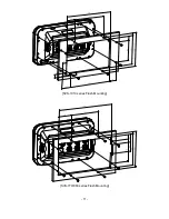
Page 11: ...11 SVS 1010 series Flush Mounting SVS 770 880 series Flush Mounting...

Page 12: ...ng the earth as illustrated on the following figure The GPS constellation Note that position is repeatedly fixed through the following three steps while any 3 satellites are in line of sight The posit...

Page 13: ...locations of 3 satellites in the sky High accuracy is obtainable when the satellites are widely scattered in the sky on the Contrary accuracy is reduced when the satellites have gathered in a narrow...

Page 14: ...rted into an electronic signal by the transducer Then it is amplified in the receiver section processed in the main logic section and displayed as an image on a LCD screen Picture 3 When your boat tra...

Page 15: ...your installation 1 Keep from a metal 2 Over 4m away from a MF HF ANT VHF or HF whip ANT 3 Over 1 5m higher than MF HF ANT 4 Over 1m away from a receiving ANT 5 Don t put the GPS ANT into the range o...

Page 16: ...sider access to the rear panel of the unit for connecting power and cables to the various remote sensors The mounting surface must be flat and solid to support the unit and prevent vibration There sho...

Page 17: ...a safe place to prevent damage during the rest of the installation process Power Connection Power is supplied to the Unit through a connector on the rear panel of the display unit Route the power cabl...

Page 18: ...se 45 50kHz 12 200kHz Bronze thru Hull Tilted Element Flush Mount Depth Temperature Only 2 375 B 60 12 CX for 8 to 15 hull dead rise 45 50kHz 12 200kHz Bronze thru Hull Tilted Element Flush Mount Dept...

Page 19: ...e using cable clamps These clamps are available from your local marine equipment supplier If you do not want to expose the cable on the deck you may drill a new hole 3 4 or 19mm through the transom fo...

Page 20: ...power wiring as much as possible from other devices See the section on EMC Installation Guidelines 4th If you need to extend the power wiring by more than 10 feet use a larger wire size This will allo...

Page 21: ...e transducer cable Remove the large hex nut from the housing and slide it over the end of the cable 4th Thread the cable through the hole to the inside of the hull Never pull or carry the transducer i...

Page 22: ...or the wood to swell after the vessel is put in the water Be sure that the correct end of the transducer is pointing forward see Picture 1 1 8th Remove any excess sealant from the outside of the unit...

Page 23: ...y the starboard side of the boat This will reduce any interference cause by air bubbles If your boat has twin propellers outboard or inboard outboard place the transducer near the centerline of the bo...

Page 24: ...o the water line 4th Hold the bracket and the wedge if used against the transom and trace the position of the screw slots 5th Remove the bracket The screws in the outer slots should be placed about 1...

Page 25: ...25 Installation of the Transducer 7th Tilt the transducer in the brackets until it is positioned as illustrated in Picture 1 3 8th Once the bracket is in the correct position you can tighten the screw...

Page 26: ...to confirm a selection or entry Change the chart of scale Open the menu Select the Goto function Select the configuration modification you wish Select the activated section Press to place a waypoint...

Page 27: ...push the end of the everything to confirm a selection or entry Change the chart of scale and Setting up the depth range Open the menu Select the Goto function Select the configuration modification yo...

Page 28: ...28 1 3 2 Turn off Keep pressing to switch off 1 3 3 Adjust brightness Pressing Fig 1 1 and controlling the brightness with 1 3 4 Use day night mode Pressing Fig 1 1 and changing the day and night with...

Page 29: ...29 2 Specification of the connectors...

Page 30: ...icon The present position Cursor Showing the cursor icon AIS target Showing the received AIS target Data bar Showing various data on the top or bottom Cursor INFO The information of the cursor WPT IN...

Page 31: ...en colors Depth bar The current depth Low Frequency Showing 50KHz High Frequency Showing 200KHz LF INFO The information of Low Frequency 50KHz HF INFO The information of High Frequency 200KHz Data bar...

Page 32: ...32 3 3 Navigation Data page 3 3 1 Navigation Data Type1 3 3 2 Navigation Data Type2...

Page 33: ...nt WPT name Direction of steer The best direction of the steering WPT icon The remaining distance of the WPT Vessel The out of the range from the best XTE Range The range of the XTE alarm Navigation D...

Page 34: ...34 3 5 Steering page WPT name Name of the WPT Direction of steer The best direction of the steering WPT icon Showing the WPT and the bearing Navigation Data Information of the various data...

Page 35: ...ition of SAT Position of the satellites SNB Graph Showing the WPT and the bearing Navigation Data Information of the various data Colors of the GPS status Black Tracked but no signal Blue Tracked but...

Page 36: ...ode Data bar has three meanings as below 4 1 1 GPS Showing the largest LAT LON 4 1 2 HY Showing the LAT LOT SOG COG and user data 4 1 3 NAV You can view detailed information about the navigation data...

Page 37: ...37 Fig 1 2 1 The data bar is coming as Fig 1 2 1 and choose the frame with Four frames are available as Fig 1 2 2 Fig 1 2 2 When choosing the frame setting up in each box as Fig 1 2 3 Fig 1 2 3...

Page 38: ...ng the data bar position on the top or bottom 5 Cursor 5 1 Calling the cursor Press on the chart the cursor comes out 5 2 Moving Press the cursor is moving to the direction Press together the cursor i...

Page 39: ...INFO window Cursor Cursor information window Shown Hidden 6 Page PAGE Choosing the various pages that set up pages or customized Move the red box to choose the page Fig 1 3 6 1 Page mode MENU Advance...

Page 40: ...Modify After choosing the page in Fig1 3 keep pressing until the window comes out as Fig 1 3 1 Fig 1 3 1 Choosing the frame with Two frames as Fig 1 3 2 Fig 1 3 2 After choosing the box choose the pag...

Page 41: ...41 7 Active ACTIVE When pressing ACTIVE the red box moves to chart plotter or sonar All key functions change to chart plotter or sonar Selected red color...

Page 42: ...of Navigation data pages 8 1 1 Type1 Large LAT LON as Fig 1 6 1 Editing the LAT LON is unavailable 8 1 2 Type2 Various data as Fig 1 6 2 Fig 1 6 1 Fig 1 6 2 8 2 Edit If there is no navigation data on...

Page 43: ...43 Fig 1 6 3...

Page 44: ...e the MOB function 9 1 Inputting Keep pressing until the window comes out as Fig 10 1 and then MOB comes out with alarm 9 2 Exiting the alarm When alarming press to cancel the alarm 9 3 Removing While...

Page 45: ...45 10 Memory Card 10 1 SVS 1010 series Inserting the SD micro SD as Fig 1 7 1 Fig 1 7 1 10 2 SVS 880 770 series Inserting the SD micro SD as Fig 1 7 2 Fig 1 7 2...

Page 46: ...name and you will be able to store many WPT in the micro SD 11 2 Route Route can be stored in a micro SD When storing give it a name and you will be able to store many routes in the micro SD 11 3 Tra...

Page 47: ...o SD When storing give it a name and you will be able to store many user lines in the micro SD 11 5 User Name User Name can be stored in a micro SD When storing give it a name and you will be able to...

Page 48: ...icro SD All of WPT in the micro SD show on the list Choose one of them and it will show There are two ways to load WPT First showing the stored WPT as well as the existing on the sceen After loading t...

Page 49: ...m the stored micro SD Index will be a standard in Type2 After choosing the index stored it 12 4 User Line User line loads from the stored micro SD All of user line in the micro SD show on the list Cho...

Page 50: ...ot store shows up Choose one of them to exit If you have one WPT in the route the WPT will be stored If you have more than two all of WPT and the route will be stored together 1 2 Goto type2 1 2 1 Set...

Page 51: ...me Name of the WPT Symbol Symbol of the WPT Color Color of the WPT Latitude Longitude LAT LOT of the WPT Depth Depth of the WPT Bearing Bearing between the WPT and the present position Range Distance...

Page 52: ...w when inputting WPT 2 3 Setting WPT Color MENU WPT Color Choose the color and press ENTER The chosen color will show when inputting WPT 2 4 Creating 2 4 1 Creating on the list MENU User data WPT List...

Page 53: ...ng on the chart Call the cursor and move the position where you want and press The current symbol color show for the WPT 2 5 Erasing 2 5 1 Erasing on the list MENU User data WPT List Choose the WPT yo...

Page 54: ...on the WPT and press ENTER 2 Choose Move 3 Move the WPT to the position where you want to move and press ENTER 2 8 Navigating 2 8 1 Navigating on the list MENU User data WPT List GOTO Choose the WPT o...

Page 55: ...55 2 9 Sorting MENU User data WPT List MENU Sorting the order of WPT s on the list...

Page 56: ...data WPT List Editing the WPT on the list 1 Choose the WPT as the blue and press ENTER 2 Choose the item as the green and you may begin to edit 3 After finishing press to exit Edit Selected green col...

Page 57: ...d WPT Name Name of the route Number of WPT Number of WPT in the route Total distance Total distance of the route Display Shown Hidden the route on the chart Date Time Date and time of the WPT when sto...

Page 58: ...Name of the WPT Symbol Symbol of the WPT Color Color of the WPT Latitude Longitude LAT LOT of the WPT Depth Depth of the WPT Bearing Bearing between the WPT and the present position Range Distance bet...

Page 59: ...e second is Creating new route on the list 3 3 1 Using GOTO Use GOTO type1 and create a route Press ENTER to start Press to exit and choose Store if needed 3 3 2 Creating new route on the list MENU Us...

Page 60: ...edit MENU User data Route List PAGE Choose the route on the list and press The window of Route detail shows 3 5 1 Adding WPT Two ways to add WPT 3 5 1 1 Adding the stored WPT MENU User data Route List...

Page 61: ...000 points by colors The second is to divide 50 000 points in five rooms and you can store 10 000 points for the maximum in each room Tracking has two types by time and by distance 4 1 Track on off M...

Page 62: ...ness MENU User data Track Track Setup Thickness Setting the track thickness 4 4 Track Color MENU Track Color Choose the color and press ENTER The number next the color shows the number point of the tr...

Page 63: ...Erase Press 4 5 2 Type2 MENU User data Track Track Setup Type2 4 5 2 1 Select index MENU User data Track Select Index Five sections in the index The maximum is 10 000 points in each section In Type2 s...

Page 64: ...nd time of the track room when stored Color Color of the track room On Off Shown the track On OFF Display Show Hidden the track room Start Point The beginning of the track room End Point The end of th...

Page 65: ...t B 3 The cursor windows provide the distance and bearing between A and B 4 Press to exit 6 User Line Adding lines directly on the chart 1 Call the cursor 2 Press ENTER and User Line shows 3 Move the...

Page 66: ...d move it to the point 2 Press ENTER and choose User Name 4 Inputting letters with 5 Press to exit 8 Correction Offset When the chart position is wrong making it correct 1 Call the cursor and move it...

Page 67: ...67 The maximum range of Correction Offset is 5nm...

Page 68: ...of the Main Screen while the map moves under it 1 3 Course Up MENU Advance Map Setup Map Orientation Up mode The Course Up mode screen orientation is determined by whether or not navigation is in pro...

Page 69: ...the map scale on the display 2 5 Palette It is possible to the palette used to enhance the visibility of the screen depending on the surround light condition The possible choices are listed in the tab...

Page 70: ...size the default setting is normal 2 9 1 3 Mixing Level When the map coverage at the current zoom level does not fill the entire screen the chart plotter draws the rest of the map expanding the cartog...

Page 71: ...D are displayed if we are in a charts level contained in the C CARD the next four charts level are displayed the default setting is auto 2 9 1 6 Multi Language Select language for name of the place li...

Page 72: ...ch are set according to the absolute minimum maximum values of that particular day The color of the arrow on the tide gauges indicates changes in the tide height Red increasing tide current height Blu...

Page 73: ...y depth contours up to 20 meters 66 feet All all depth contours are displayed 2 9 2 4 Chart Details The chart detail setting determines the amount of cartographic detail Shown in the chart application...

Page 74: ...setting is circle 3 4 Orient Resolution Sets you preferred Rolling Road Scale the default setting is 0 4 Cursor Icon Select the cursor icon between Cross to Arrow the default setting is Cross 5 Alarm...

Page 75: ...es you notice with alarm the default setting is 0 05nm 5 3 Interval 5 3 1 Interval Alarm It alarms every time you set the default setting is OFF 5 3 2 Interval Time The time is available from one minu...

Page 76: ...and the tracked target based on your vessel s speed and direction and the target s speed and direction TCPA Time to Closest Point of Approach is the time remaining until the CPA will occur Name Name...

Page 77: ...nge Sleeping target is represented by a small oriented triangle Lost Target When the AIS info is not received from that vessel The presentation will be marked X on the target 3 AIS information window...

Page 78: ...78 4 Quick INFO on AIS target Choose AIS information window on Fig 3 1 and AIS data shows under the AIS target Up to four kinds of data is available to choose in Quick INFO...

Page 79: ...lay on the screen on or off the default setting is on 2 List 2 1 List Fig 3 2 Name Name of the AIS target MMSI MMSI of the AIS target Range Distance between the AIS target and the present position BRG...

Page 80: ...80 2 2 Detail Choose the AIS target and press ENTER 2 3 Goto Choose the AIS target and press...

Page 81: ...ange rings centered on your current position the default setting is OFF 4 AIS target size Choose the size of AIS target the default setting is Large 5 Display vessels by Color Different types of AIS t...

Page 82: ...pproach alarm this allows you to set a distance when the alarm will sound if a vessel comes within that distance the default setting is OFF 8 2 CPA Range The values allowed are from 0 1nm to 10nm the...

Page 83: ...0 Others 10 1 Labels on vessels This menu controls what details are displayed alongside the vessels icons on the chart display 10 2 Cursor Box info When you move the cursor in chart mode over an AIS t...

Page 84: ...y other station has received this SART message if not take the appropriate action 10 4 Test View Showing the text of the SART Message the default setting is off 10 5 Fishing net 10 5 1 Fishing net Dis...

Page 85: ...85...

Page 86: ...hoose the frequency with the The chosen frequency shows in red 2 Auto Manual Gain Press ENTER to choose AUTO Manual of Gain 3 Gain STC Choose Gain and STC with 4 Controlling Gain 1 Choose the frequenc...

Page 87: ...he sea bottom in the lower part of the screen The depth scale indicates the depth range appearing in the display Bottom contours and fish echoes are displayed at the depths where they are detected If...

Page 88: ...ted Sonar into two sections The left hand section displays a Normal Mode image The right hand section of the screen displays the Sonar image relative to the sea bottom The sea bottom appears as a stra...

Page 89: ...89 zoom or lock 7 VRM WPT The VRM movable marker shown by the green line can be moved up and down It is convenient to measure the depth by aligning with the target such as school of fish...

Page 90: ...from the shift range For example if you raise 5m of shift at 20m range the surface shall start 5m and the bottom range shall be 25m the default setting is 0m 1 4 Mode Fish finder modes are selectable...

Page 91: ...A scope A scope shows the research under the water by a scope to see the environment under the water the default setting is OFF 2 1 2 Image Speed Select the speed of Fish finder image from 4X until 1...

Page 92: ...of the bar is deleted one by one 2 2 3 Screen Color Select he back ground color of the Fish finder for your convenience 2 3 Pulse Select the pulse of the output from the transducer Levels are among L...

Page 93: ...High Range It alarms when the set high temperature is out of the range the default setting is 0 2 5 2 3 Low alarm It alarms when the set low temperature is out of the range the default setting is OFF...

Page 94: ...el If the alarm is on you are able to choose the color level 2 6 Water Temp The error of water temp value can be corrected Setting 10 0 10 0 10 10 F The default setting is 0 2 7 TD Setup Choosing the...

Page 95: ...95...

Page 96: ...tion 1 4 LOT Modification There could be a receiving signal error from satellites If it is on the longitude modify in the longitude modification 1 5 POG filtering Step 1 OFF 59 MAX the POG Filter When...

Page 97: ...m kt kilometer kilometers per hour km kmh yard knot yd kt 1nm 1 852km 1kt h 1 852km h less than 1nm display in yard and over 1nm display in mile the default setting is Nm Kt 2 1 2 Depth Select desired...

Page 98: ...the default setting is 12 hour 2 3 3 Date Format Sets you preferred date among YY MM DD MM DD YY or DD MM YY the default setting is YY MM DD 2 3 4 Month format Sets the preferred date between Charact...

Page 99: ...destination OFF GPBWC Bearing and distance to waypoint ON SYPLT Samyoung autopilot OFF 2 4 2 Transmit Available to adjust transmit speed of input output in each ports 2 4 3 Buzzer It is can be buzzer...

Page 100: ...ation data section except activated the sonar section 2 4 5 3 Sidebar 2 4 5 3 1 Display Shown Hidden Sidebar the default setting is off 2 4 5 3 2 Position Choosing the position of Sidebar on the right...

Page 101: ...as many as you want and those will show on the track color window 2 4 5 6 Alpha Blending You can set the transparency of the background in data bar and sub screen 2 4 5 7 Page mode It is a select the...

Page 102: ...gister the remote control 3 7 Initialization 3 7 1 User Initialization The stored setting is initialized in the user setting 3 7 1 Setup Initialization Reset without deleting user data 3 7 2 Factory I...

Page 103: ...103...

Page 104: ...Reacquisition 162 dBm 5 Nav Update 1Hz 5Hz 6 Support DGPS SBAS EGNOS WAAS MASA GAGAN Chart plotter specification 1 Display Method Mercado Projection 2 Display Mode True motion N S E W up Course up He...

Page 105: ...105 Standard Equipment Configuration List Display unit External GPS ANT option Manual Protector Mounting Bracket Knobs Fuse Bolt Power cable Dimension...

Page 106: ...165 dBm Reacquisition 162 dBm 5 Nav Update 1Hz 5Hz 6 Support DGPS SBAS EGNOS WAAS MASA GAGAN Chart plotter specification 1 Display Method Mercado Projection 2 Display Mode True motion N S E W up Cours...

Page 107: ...s 4 1 2 1 1 1 1 2 1 4 1 8 1 16 1 32 and stop 6 Rejection Interferences rejection 3 levels Noise rejection 4 levels 7 Function Gain auto manual Range auto manual Depth with shift auto manual Pulse leng...

Page 108: ...dBm Reacquisition 162 dBm 5 Nav Update 1Hz 5Hz 6 Support DGPS SBAS EGNOS WAAS MASA GAGAN Chart plotter specification 1 Display Method Mercado Projection 2 Display Mode True motion N S E W up Course u...

Page 109: ...109 Standard equipment configuration List Display unit External GPS ANT option Manual Protector Mounting Bracket Knobs Fuse Bolt Power cable Dimension...

Page 110: ...2 dBm 5 Nav Update 1Hz 5Hz 6 Support DGPS SBAS EGNOS WAAS MASA GAGAN Chart plotter specification 1 Display Method Mercado Projection 2 Display Mode True motion N S E W up Course up Head up 3 Latitude...

Page 111: ...s 4 1 2 1 1 1 1 2 1 4 1 8 1 16 1 32 and stop 6 Rejection Interferences rejection 3 levels Noise rejection 4 levels 7 Function Gain auto manual Range auto manual Depth with shift auto manual Pulse leng...

Page 112: ...dBm Reacquisition 162 dBm 5 Nav Update 1Hz 5Hz 6 Support DGPS SBAS EGNOS WAAS MASA GAGAN Chart plotter specification 1 Display Method Mercado Projection 2 Display Mode True motion N S E W up Course up...

Page 113: ...113 Standard equipment configuration List Display unit External GPS ANT option Manual Protector Mounting Bracket Knobs Fuse Bolt Power cable Dimension...

Page 114: ...2 dBm 5 Nav Update 1Hz 5Hz 6 Support DGPS SBAS EGNOS WAAS MASA GAGAN Chart plotter specification 1 Display Method Mercado Projection 2 Display Mode True motion N S E W up Course up Head up 3 Latitude...

Page 115: ...s 4 1 2 1 1 1 1 2 1 4 1 8 1 16 1 32 and stop 6 Rejection Interferences rejection 3 levels Noise rejection 4 levels 7 Function Gain auto manual Range auto manual Depth with shift auto manual Pulse leng...

Page 116: ...Present water temperature TOT TIME Total Time Total using time VOLTAGE Present voltage unstable voltage shows in red TTG Time To Goal Remaining time to the destination ETA Estimated time of arrival XT...

Page 117: ...117...

Page 118: ...0301P SI TEX MARINE ELECTRONICS DATE 2014 04 07 1 2 SCALE MATERIAL MODEL DES BY PER N CHK BY SVS 560 460 series Souk J E DRA BY Kim Y S Kim Y S Kim Y S 1 8 6 7 5 3 4 2 Power Calbe WIRE COLOR PIN FUNCT...

Page 119: ...119 KIM Y S KIM Y S KIM Y S D J PARK S5 PA90101 SVS 560 460 series DESCRIPTION DWG NO DES BY 1 1 SCALE PER N MODEL CHK BY MATERIAL DRA BY External GPS Antenna SI TEX MARINE ELECTRONICS DATE 03 26 2014...

Page 120: ...ranty Exceptions This Warranty and Proof of Purchase must be made available to the authorized SI TEX Marine Electronics Inc service location or dealer at the time of service LIMITED WARRANTY EXCEPTION...

Page 121: ...ranty and are covered by warranty for a period of one year for both parts and labor SI TEX Marine Electronics Inc will not at any time assume any costs or labor charges for checkout or external line f...

Page 122: ...contact numbers and e mail address for SI TEX Customer Service are SI TEX Main Office 1 631 996 2690 SI TEX Fax 1 631 996 2693 SI TEX Service E mail address service si tex com SI TEX Customer Support...

Reviews: