Communication System Manual
3VF, 3WN, 3WS Circuit-Breakers
Version 1.0 (05/98)
Copyright Siemens AG 1998. All rights reserved.
1
Contents
1 INTRODUCTION
4
1.1 Contents of this manual
4
1.2 Explanation of terms and advantages of "communication"
4
1.3 Explanation of terms "PROFIBUS" and "PROFIBUS-DP"
5
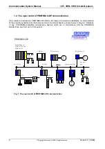
1.4 The open world of PROFIBUS-DP communication
6
2 3VF CIRCUIT-BREAKERS
7
2.1 Design and mode of operation
7
2.1.1 Communication via PROFIBUS-DP
7
2.1.2 Data exchange
8
2.1.3 Hardware and software connections of 3VF
10
2.1.4 Connecting 3VF to the communication system
12
2.1.5 Selection and ordering data
17
2.1.6 Parameter file
19
2.2 Technical data
25
2.3 Supplementary literature on 3VF communication
25
3 3WN6 CIRCUIT-BREAKERS
26
3.1 Mode of operation and design
26
3.1.1 General mode of operation of 3WN6 circuit-breaker communication via PROFIBUS-DP
26
3.1.2 Hardware and software requirements
26
3.2 Bus connection functionality
28
3.3 Procedure for connection to communication system
31
3.4 Displaying the data in the 3WN6 circuit-breaker
37
3.4.1 Addressing the 3WN6 functions on PROFIBUS-DP:
37
3.4.2 List of acyclic 3WN6 messages on PROFIBUS-DP
39
3.4.3 List of cyclical 3WN6 data traffic on PROFIBUS-DP
52
3.4.4 Examples of (acyclic) message requests:
54
3.4.5 Time response of data traffic
55
3.5 Description of software block required for utilizing communication functions
with SIMATIC S5 and S7
59
3.5.1 CPU and DP master types
59
3.5.2 Displaying data in PROFIBUS-DP
59
3.5.2.1 Parameterization
59
3.5.2.2 Configuration
59
3.5.2.3 Diagnostics
60
3.5.2.4 Data
60
3.5.3 STEP 5 program
63
3.5.3.1 Brief outline of software block tasks
63
3.5.3.2 Preparing to use the software block
63
3.5.3.3 General information and adaptations
63


