Siemens
Siemens
Siemens
Siemens
Siemens Industry
Industry
Industry
Industry
Industry,,,,, Inc.
Inc.
Inc.
Inc.
Inc.
Building
Building
Building
Building
Building T
TT
TTec
ec
ec
ec
echnologies Di
hnologies Di
hnologies Di
hnologies Di
hnologies Division
vision
vision
vision
vision
P/N 315-033035-6
INTRODUCTION
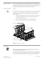
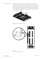
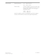
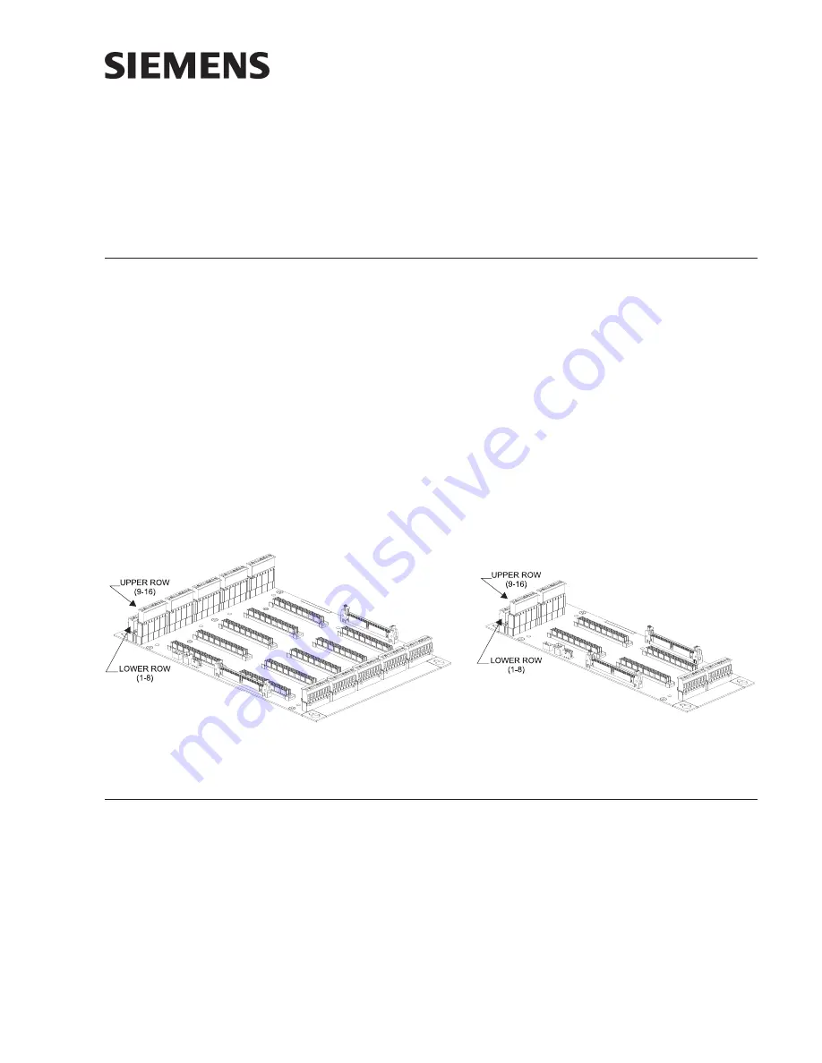
The Model CC-5 Cardcage from Siemens Industry, Inc., (see Figure 1) has five card
slots and occupies two positions on the studs in the backbox or on the optional CAB-
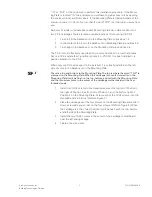
MP Mounting Plate. The Model CC-2 Cardcage (see Figure 2) has two card slots and
occupies one position on the studs in the backbox or on the optional CAB-MP
Mounting Plate. The CC-5 and CC-2 are used for mounting all system circuit card
assemblies. They each have two removable terminal block connectors at the top and
one removable terminal block connector at the bottom of each card slot. All field-
wiring connections are made directly to the top of the cardcage while internal power
is connected to the bottom of the cardcage. The two removable terminal block
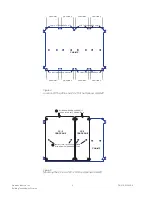
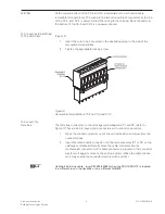
connectors at the top of each slot are arranged in two rows. The lower row is labeled
1 through 8 and the upper row is labeled 9 through 16. These removable terminal
block connectors are used for connecting power limited external equipment. The
removable terminal block connector located at the bottom of each slot is labeled 17
through 24 and is used for connecting internal power.
Figure 1
Figure 2
CC-5 Card Cage
CC-2 Card Cage
OPERATION
The CC-5 and CC-2 provide a central point for mounting circuit card assemblies. If a
card requires power, it is applied through the removable terminal block at the bottom
of the cardcage. All external devices for the card are connected to the card through
the two removable terminal blocks at the top of the cardcage. The circuit card
assemblies are connected to the HNET and CAN bus through the connectors on the
cardcage.
Note:
Boards shown without card guides installed.
System Cardcage
Installation Instructions
Models CC-5 / CC-2


