background image

P/N 315-033260-9

DEVICE PROGRAMMING UNIT (DPU)

User’s Manual

Siemens Industry, Inc.

Building Technologies  Division

Summary of Contents for DPU

Page 1: ...P N 315 033260 9 DEVICE PROGRAMMING UNIT DPU User s Manual Siemens Industry Inc BuildingTechnologies Division ...

Page 2: ......

Page 3: ...R andTRI M 15 TRI DUAL TRI D 17 Changing a Device ID 20 FS 100 Detectors and Devices 21 Smoke Detectors 21 FS TRI S FS TRI R FS TRI M FS MS and FS CZM 23 FS TRI D 24 3 Testing 27 Testing a FireFinder XLS FS 250 FC20 FC2025 FC2050 FC2005 FC922 FC924 FC901 Loop 27 Testing a Device or Detector 31 AutomaticTest 31 ManualTest 31 FireFinder XLS FS 250 FC20 FC2025 FC2050 FC2005 FC922 FC924 FC901 32 FDOOT...

Page 4: ...USER S MANUAL CONTENTS ii TABLE OF CONTENTS Table of Contents cont 5 Maintenance 43 Updating the Firmware 43 Charging the Internal Batteries 45 Replacing the Batteries 45 Troubleshooting 46 2011 Copyright Siemens Industry Inc ...

Page 5: ...l adaptor must be used for programming detectors that require a DB 3S base The DPU operates from either rechargeable or off the shelf non rechargeable batteries that are located in an easily accessible battery compartment The DPU is supplied with a carrying strap six nickel metal hydride NiMH batteries cables banana plug to alligator clip adaptors an external power supply and a DB 3S base adaptor ...

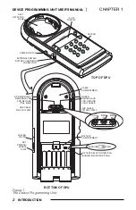
Page 6: ...E POWER SWITCH BATTERY SELECTION SWITCH SHOWN IN NiMH POSITION GREEN BANANA JACK FOR GROUND FAULT CABLE USE CABLE P N 555 133920 ALKALINE NiMH BOTTOM OF DPU BATTERY COMPARTMENT CABLE COMPARTMENT RJ11 PRINTER UPDATE PORT SLIDING COVER RED AND BLACK BANANA JACKS FOR DEVICES TRIs MSIs USE CABLE P N 555 133891 8 9 0 C 2 3 4 5 6 7 1 ALKALINE NiMH RED BANANA JACK BLACK BANANA JACK GREEN BANANA JACK ...

Page 7: ...side of the display These switches are used to select menu items on the display Keypad The keypad is a 12 button alphanumeric keypad with digits 0 through 9 the letter C and a blank key The C key adjusts the LCD and Backlighting display from the Main Menu The blank key is nonfunctional at this time Power Switch The push button power switch is located on the left side of the DPU Pressing the Power ...

Page 8: ...cept either six Alkaline AA or six Nickel Metal Hydride NiMH AA batteries Charging Alkaline batteries may damage the DPU and could cause personal injury Inside the battery compartment is a Battery Selection Switch Refer to Figure 1 for the location of the switch This switch must be set to the type of battery being used Setting the switch in the NiMH position enables the batteries to be charged whe...

Page 9: ...MH batteries before using them for the first time or after not using them for a long time Do not load the batteries in the opposite direction to that shown in these instructions Getting Started There are just a few steps that are necessary before you are ready to start programming devices and detectors using the DPU Remove the battery separator strip before using the DPU by pulling the strip down ...

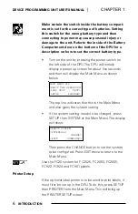
Page 10: ...five seconds and then will display the Main Menu as shown below MAIN MENU XLS SELECT THE OPERATION LOOP TEST TEST SETUP PROGRAM The top line indicates that this is the Main Menu and also gives the system setting If the system setting needs to be changed press SETUP then SYSTEM at the Main Menu The display will show SELECT SYSTEM SYSTEM XLS CHANGE EXIT DOWNLOAD Then press the CHANGE button to set t...

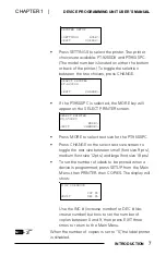
Page 11: ...screen SELECT PRINTER PT 9500PC MORE EXIT CHANGE Press MORE to select text size for the PT 9500PC Press CHANGE on the select text size screen to toggle the text size between small font size 9 pts medium font size 12 pts and large font size 18 pts To set the number of labels to be printed when a device is programmed press SETUP from the Main Menu then PRINTER then COPIES The display will show OF CO...

Page 12: ...gher numbers corresponding to higher contrast Backlight numbers run from 1 to 10 with the higher numbers corresponding to brighter backlighting Pressing BLT DOWN beyond 1 will turn off the backlighting LCD BACKLIGHT LCD UP BLT UP LCD DOWN BLT DOWN To adjust the LCD contrast use LCD UP and LCD DOWN To adjust the backlight level use BLT UP and BLT DOWN When the settings are satisfactory press the C ...

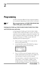
Page 13: ...ther configuration data such as ASD settings usage and the type of the inputs on HTRIs are sent from the applicable panel s programming tool Refer to Figure 2 on pages 10 11 to connect the device to be programmed At the Main Menu press PROGRAM The display will be a screen similar to the following PROGRAM P2 DEVICE LOOP 012 ADDRESS 111 LOOP ADDRESS EXIT PROGRAM Press LOOP The cursor will appear und...

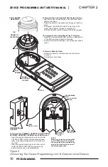
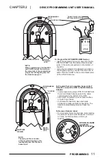
Page 14: ...base Rotate the detector clockwise until it stops and locks in place Rotate the detector counterclockwise until stop is reached Pull detector out of base Figure 2 ConnectingThe Device Programming UnitTo Detectors And Devices CABLE P N 555 133891 BOTTOM OF DPU HMS MANUAL STATION To Program Test HMS MSI HTRI TRI HCP ICP ICP B6 FDCIO422 HZM CZM 1 CZM 1B6 Devices And ILED Insert the programming plug i...

Page 15: ...detector automatically stops and locks into place Push detector head into the base while rotating the detector head counterclockwise Continue to rotate counterclockwise until stop is reached CABLE P N 555 133891 WITH ALLIGATOR CLIPS BOTTOM OF DPU ORG BLK BLK GRN ORG RED RED ALL CONNECTIONS ARE POWER LIMITED EARTH GND HTRI M To Program Test HTRI M TRI B6M Devices Insert the programming plug in one ...

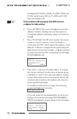
Page 16: ...ce is programmed successfully the label printer will print the number of labels selected at setup and and the DPU will display the message PROGRAMMED OK HFPT 11 LOOP 012 ADDRESS 111 PROGRAMMED OK EXIT CHANGE Press EXIT to return to the Main Menu To change the current setting of the detector or device press CHANGE to return to the loop and address setting screen Removing or disconnecting the device...

Page 17: ...N 515 033925 supplied with the DPU in order to program these devices Refer to Figure 2 on pages 10 11 to connect the device to be programmed In addition to programming the address the DPU allows usage information to be programmed into MXL devices and detectors therefore the screens presented to the user will vary depending on the device being programmed Smoke Detectors To program an MXL smoke dete...

Page 18: ...printing If the loop and address information is correct press PROGRAM The DPU will indicate that it is program ming the unit and when programming is complete will display a screen similar to the following FP 11 LOOP 012 ADDRESS 41 PROGRAMMED OK EXIT CHANGE Press EXIT to return to the Main Menu Press CHANGE to return to the beginning and change the settings The MXL device address range is 01 to 60 ...

Page 19: ...ks in the cable compartment of the unit Refer to Figure 2 pages 10 11 Then follow the procedure below With the DPU displaying the Main Menu press the PROGRAM button The DPU will prompt the user to insert or connect a device or detector The DPU is not equipped with polarity reversal forTRI devices and MS manual stations If the display searches for a device for longer than two seconds reverse the po...

Page 20: ...r The loop number will appear only if the DPU has been configured for label printing Press EXIT to return to the previous Menu To continue changing other settings of the same device press NEXT The DPU will show a display similar to the following TRI AL NO LOOP 012 ADDRESS 41 TROUBLE N C EXIT PROGRAM This screen allows the usage and the contact state of the input to be changed Press theTROUBLE butt...

Page 21: ... ADDRESS 41 PROGRAMMING FAILED EXIT RE DO Press EXIT to return to the Main Menu Press RE DO to reprogram the detector If theTRI was programmed correctly and the device is removed the searching screen will display TRI DUAL TRI D TRIs must be programmed using cable P N 555 133891 that is stored in the cable compartment in the bottom of the DPU Before starting to programTRIs open the cable compartmen...

Page 22: ...ll appear on the screen first scroll to the higher address using the NEXT button To change the contact state of the input the device usage the loop number or the address to which the device will be set press the SETTINGS button The DPU will show a display similar to the following DUAL TRI AL AL NO NO LOOP 012 ADDRESS 41 LOOP ADDRESS EXIT NEXT Press the LOOP or ADDRESS button to move the cursor ove...

Page 23: ...ettings for input 2 2 press NEXT The display will appear similar to the following TRI D 2 N O ALARM LOOP 012 ADDRESS 41 TROUBLE N C EXIT PROGRAM Use theTROUBLE and N C buttons to change the settings as explained above If the settings are correct press PROGRAM to program theTRI If label printing is selected up to nine labels will be printed If theTRI is programmed correctly the display will appear ...

Page 24: ... connect a device or detector When the DPU finds the detector it will display the detector type Following is an example screen FP 11 LOOP 012 ADDRESS 41 ID SETTINGS EXIT PROGRAM Press the ID button The display will be similar to the following FP 11 012 41 SELECT THE NEW ID ID 60P PT EXIT OK Press the ID 60P PT button to cycle through the possible IDs that may be set The DPU will only present IDs t...

Page 25: ...H B 1 I L I B 1 I L I H B I 0 6 D I B I 0 6 D I FS 100 Detectors and Devices Usage and configuration information for FS 100 devices and detectors may only be programmed by the panel or configuration tool The DPU is only capable of setting the address of these devices Smoke Detectors To program an FS 100 smoke detector the system must be set to FS 100 refer to page 6 Begin with the DPU displaying t...

Page 26: ...T to return to the Main Menu Press CHANGE to return to the beginning and change the settings The FS 100 device address range is 01to 60 If the data entered is out of range the following screen will flash for 3 seconds INCORRECT ENTRY If the smoke detector was not programmed correctly the display will show a screen similar to the following FS DPT LOOP 1 ADDRESS 41 PROGRAMMING FAILED EXIT RE DO Pres...

Page 27: ...ying the Main Menu press the PROGRAM button The DPU will prompt the user to insert or connect a device or detector The DPU is not equipped with polarity reversal for FS TRI devices FS MS manual stations and FS CZM modules If the display searches for a device for longer than two seconds reverse the polarity of the programming cable Connect the programming cable to the device to be programmed Refer ...

Page 28: ... ADDRESS 41 PROGRAMMING FAILED EXIT RE DO Press EXIT to return to the Main Menu Press RE DO to reprogram the detector If the device was programmed correctly and the device is removed the searching screen will display FS TRI D FS TRIs must be programmed using cable P N 555 133891 that is stored in the cable compartment in the bottom of the DPU Before starting to program FS TRIs open the cable compa...

Page 29: ...secutive addresses If the settings are correct press PROGRAM to prog ram the FS TRI If label printing is selected up to nine labels will be printed If theTRI is programmed correctly the display will appear similar to the following FS TRI D AL AL NO NO ADDRESS 41 PROGRAMMED OK EXIT CHANGE Press EXIT to return to the Main Menu Use the CHANGE button to go back and change a setting If the FS TRI was n...

Page 30: ...DEVICE PROGRAMMING UNIT USER S MANUAL CHAPTER 2 26 PROGRAMMING This page has been left intentionally blank ...

Page 31: ...er XLS FS 250 FC20 FC2025 FC2050 FC2005 FC922 FC924 FC901 and it operates only when the DPU is powered from AC Be sure to disconnect the wire between the device and or detector loop and the system before performing the loop test Follow the procedure below to test a loop of FireFinder XLS FS 250 FC20 FC2025 FC2050 FC2005 FC922 FC924 FC901 detectors and devices Connect the DPU to an AC wall outlet u...

Page 32: ...e P N 555 133920 into the green jack in the cable compartment in the bottom of the DPU Connect the alligator clip on the other end of Cable P N 555 133920 to Earth Ground Attach the two alligator clip adaptors provided to the programming plug on end of cable P N 555 133891 Connect one clip to the wire of Line 1 from the device loop to be tested Connect the other clip to the wire of Line 2 from the...

Page 33: ...FP photo thermal detector Ex amples of H Series Screen A and FD UL Series Screen B displays are shown below P 001 T 023 I 020 D 000 R 000 M 000 C 000 Z 010 002 EXIT NEXT Q 002 E 022 W 021 G 000 V 000 N 011 EXIT NEXT Screen A Screen B Pressing NEXT shows further summary screens Pressing EXIT returns the DPU one screen up to the top of the loop test display Press the DETAIL button to display the typ...

Page 34: ... e p p a l l i w n m u l o c t s r i f e h t n i d e t s i l s r e t t e l e h T s i r e t t e l e h t n e h W t s e t p o o l 1 0 9 C F 4 2 9 C F 2 2 9 C F 5 0 0 2 C F 0 5 0 2 C F 5 2 0 2 C F 0 2 C F 0 5 2 e l b u o r t r o m r a l a n i s i e c i v e d e h t t a h t s e t a c i d n i t i g n i h s a l f 1 0 9 C F R O 4 2 9 C F 2 2 9 C F 5 0 0 2 C F 0 5 0 2 C F 5 2 0 2 C F 0 2 C F S L X R O F T S...

Page 35: ...low to test a device or detector At the Main Menu pressTEST then press AUTO The DPU prompts the user to insert or connect a device Refer to Figure 2 pages 10 11 to install devices for testing When the device is detected the test is run The DPU will display the type of device tested and the address as shown below TESTING SUCCESSFUL device type here device address EXIT If the device is removed the D...

Page 36: ...found the device address and the current status of the device as shown in the screen below The manual test screen is updated once per second HFP 11 ADDRESS 002 NORMAL EXIT NEXT HFP 11 Example Pressing EXIT will return the DPU to the device test screen Pressing NEXT will display further screens of information that will vary depending on the type of device being tested Some example screens are shown...

Page 37: ...n w o d s i g n i t t e s s i h t t a h t e t o N y r o s i v r e p u S s i t a h t m e t s y s a o t d e t c e n n o c s i e c i v e d r o r o t c e t e d e h t l i t n u t l u a f e d o t t e s p u d e r e w o p D S A s e c i v e d f o s g n i t t e s y a l p s i d o s l a l l i w s i h T r o t c e t e d e h t f o g n i t t e s D S A e h T f o e t a R e l p m a x e r o f s m r a l a s s e c o r ...

Page 38: ...r An example of a manual test for the FDOOTC441 OOHC941 follows with a description of the diagnostic information given inTable 4 The NEXT button may be used to page to the next screen of information FDOOTC441 OOHC941 ADDRESS 022 NORMAL EXIT NEXT FDOOTC441 OOHC941 or FDOOT441 Example Screen 1 S N 0494AB4 USAGE1 MULTI 2 USAGE2 THERMAL 5 EXIT NEXT FDOOTC441 OOHC941 or FDOOT441 Example Screen 2 IEC CL...

Page 39: ...e d s i e d o m n o i t a r e p o e h T 1 t n e n o p m o c t u p n I F F O r o d e n i f e d n U e k o m S a i r e t i r c 2 E G A S U l a m r e h T r e h t i e s a d e n i f e d s i e d o m n o i t a r e p o e h T 2 t n e n o p m o c t u p n I F F O r o d e n i f e d n U e u l a v x E G A S U l l i w s i h T t n e n o p m o c t u p n i e h t r o f 5 1 o t 0 0 e u l a v D I t e s r e t e m a r a ...

Page 40: ... four usage settings The input channel status is displayed as NORMAL for Usage1 and Usage2 in Example Screen 2 Screen 3 shows the input channel status as NORMAL for Usage3 and Usage4 An example of a manual test for the FDCIO422 follows with a description of the diagnostic information given in Table 5 FDCIO422 NORMAL ADDRESS 036 S N 2F0494AB6 EXIT NEXT FDCIO422 Example Screen 1 NORMAL NORMAL USAGE1...

Page 41: ...e t l a u n a m 3 E G A S U y r o s i v r e p u S V P U S s a d e n i f e d s i e d o m n o i t a r e p O 3 h c t i w s t u p n I e h t n e h t d e t c e l e s s i L O E A _ L C f I F F O r o L O E A _ L C M R A L A r u o f f o d a e t s n i s t u p n i A s s a l C o w t e v a h o t d e r u g i f n o c s i 2 2 4 O I C D F n e h t L O E _ A _ L C o t t e s s i 4 d n a 3 s t u p n i e h t f o e n o ...

Page 42: ...D I e c i v e D e c i v e d d e t c e n n o c e h t f o r e b m u n D I e h T 1 G O L A N A C s e e r g e d n i T D S F T P D S F 1 1 T P F 1 1 P F y b d e r u s a e m e r u t a r e p m e T 2 G O L A N A s t n u o c L X M n i P D S F T P D S F 1 1 P F f o e u l a v n o i t a r u c s b O 1 T y l n o e s u y r o t c a f r o F 2 T y l n o e s u y r o t c a f r o F S S y l n o e s u y r o t c a f r o ...

Page 43: ... 0 5 2 S F A A A L r e b m u n p o o l t i g i d e e r h t o t e n o a s i L s s e r d d a t i g i d e e r h t o t o w t a s i A e b n a c s s e r d d a e h t s m e t s y s 0 0 1 S F L X M n O e h t s m e t s y s 1 0 9 C F 5 0 0 2 C F n O 0 6 o t p u S L X r e d n i F e r i F n O 0 5 o t p u e b n a c s s e r d d a 4 2 9 C F 2 2 9 C F 0 5 0 2 C F 5 2 0 2 C F 0 5 2 S F 2 5 2 o t p u e b n a c s s e...

Page 44: ... buttons to set the number of copies desired Press EXIT three times to return to the Main Menu display If the printer does not work turn off the DPU wait a few seconds and then turn it back on and try again Bulk Printing From one to nine copies of each label may be printed for a range of addresses by using the bulk print facility Following is the procedure 1 Connect the DPU to the optional printer...

Page 45: ...S of the label from 1 to 9 that you wish to print 4 When these have been set correctly press the PRINT button The DPU will then begin printing the labels and the display will indicate that printing is in progress 5 An ABORT button is provided to allow the user to cancel the printing operation and return to the bulk printing display 6 The display will indicate when the printing has been completed 7...

Page 46: ...DEVICE PROGRAMMING UNIT USER S MANUAL CHAPTER 4 42 PRINTING LABELS This page has been left intentionally blank ...

Page 47: ...2050 FC2005 FC922 FC924 or FC901 LCD Contrast and Backlight settings Label printing settings number of copies to print in Auto and Bulk printing start and end addresses used in Bulk printing Use the Siemens Module Firmware Upload Utility to update the firmware in your DPU as follows 1 Connect the PC with the download software to the update port on the DPU using cable P N 600 190704 See Figure 1 pa...

Page 48: ... If a Timeout Waiting for Configuration reply message is displayed the DPU is not communicating properly Check the cable connec tion between the PC and the DPU and the Com port selection described in Step 4 7 In the Upload utility select Session Upload file to DPU or select the Upload file to DPU button on the toolbar If the message Network Initialization Failure is displayed by the utility select...

Page 49: ...ct the external power supply to the DPU and plug the external power supply into the wall socket Recharging will take about two hours The DPU may be used during this period but the recharging time may be significantly longer Replacing the Batteries The DPU will operate using either rechargeable NiMH or non rechargeable Alkaline batteries The battery compartment is accessible on the bottom rear of t...

Page 50: ...oubleshooting When nothing shows on the display try the following 1 Press any key the unit may be in low power mode 2 Check the batteries 3 Check the power If the printer does not seem to work turn off the DPU wait a few seconds and then turn it back on and try again ...

Page 51: ......

Page 52: ...P N 315 033260 9 Siemens Industry Inc Building Technologies Division Florham Park NJ 07932 Siemens Canada Limited Building Technologies Division 2 Kenview Boulevard Brampton Ontario L6T 5E4 Canada ...

Reviews: