background image

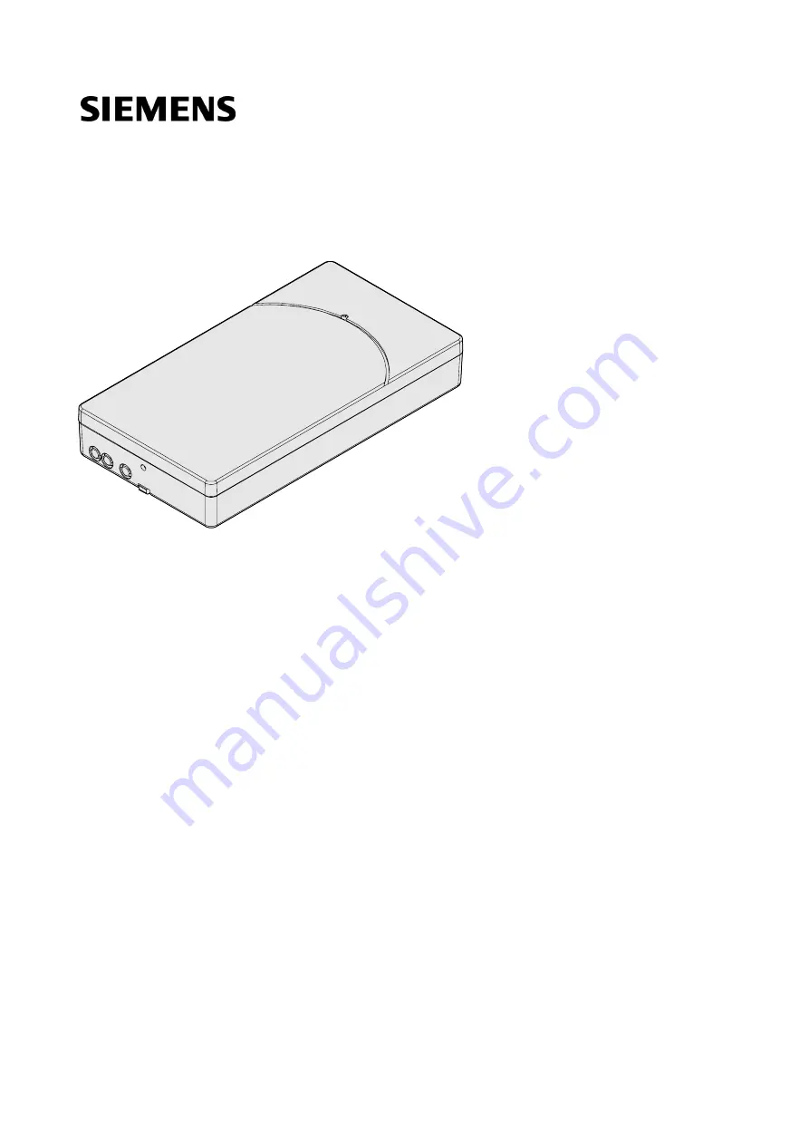
FDCW241
Radio gateway

Technical Manual

A6V10227639_k_en_--

Building Technologies

2016-11-28

Control Products and Systems

Summary of Contents for FDCW241

Page 1: ...FDCW241 Radio gateway Technical Manual A6V10227639_k_en_ Building Technologies 2016 11 28 Control Products and Systems ...

Page 2: ... communication thereof to others without express authorization are prohibited Offenders will be held liable for payment of damages All rights created by patent grant or registration of a utility model or design patent are reserved Issued by Siemens Switzerland Ltd Building Technologies Division International Headquarters Gubelstrasse 22 CH 6301 Zug Tel 41 41 724 2424 www siemens com buildingtechno...

Page 3: ...2 1 Diagnosis levels 18 3 2 2 Behavior in degraded mode 19 3 2 3 Status display on the radio gateway 19 3 3 Power supply 21 3 4 Accessories 22 3 4 1 Connection terminal DBZ1190 AB 22 3 4 2 Battery pack BAT3 6 10 22 3 4 3 Housing FDCH221 22 3 4 4 Housing base FDCH271 23 3 4 5 Housing cover FDCH272 23 3 4 6 MCL USB radio adapter FDUZ227 23 4 Planning 24 4 1 Compatibility FDnet C NET 24 5 Mounting In...

Page 4: ... 46 7 4 5 Connecting the radio cell to the detector line 48 7 5 Replacing the radio gateway and transferring data 49 7 5 1 Replacing the radio gateway FDCW241 49 7 6 Firmware update 51 7 7 Basic principles for replacing the battery pack 51 7 8 Replacing the batter pack on the radio gateway 52 7 9 Messages and consequences 53 8 Specifications 54 8 1 Technical data 54 8 2 Dimensions 58 8 3 Master ga...

Page 5: ...he function and for the products Has attended the training courses for Product Managers Project Manager Coordinates the deployment of all persons and resources involved in the project according to schedule Provides the information required to run the project Has obtained suitable specialist training for the function and for the products Has attended the training courses for Project Managers Projec...

Page 6: ... of international standard ISO 8601 format YYYY MM DD Conventions for text marking Markups Special markups are shown in this document as follows Requirement for a behavior instruction 1 2 Behavior instruction with at least two operation sequences Version option or detailed information for a behavior instruction Intermediate result of a behavior instruction End result of a behavior instruction Numb...

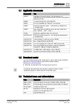
Page 7: ...6V10229261 List of compatibility for Cerberus PRO product line A6V10271323 Data sheet SWING Neural radio fire detector FDCW241 FDOOT271 FDM273 FDM275 FDM275 F A6V10347735 Installation MCL USB adapter radio FDUZ227 A6V10367669 Open Source Software OSS Licenses SWING 1 2 Download center You can download various types of documents such as data sheets installation instructions and license texts via th...

Page 8: ...tatus display on the radio gateway Compatibility FDnet C NET Basic rules for commissioning Commissioning the radio cell Maintenance troubleshooting Putting the radio cell into maintenance mode Putting the radio cell into normal operation Adding or removing radio devices Adding radio devices Removing radio devices permanently Replacing a radio device with another of the same type Replacing the radi...

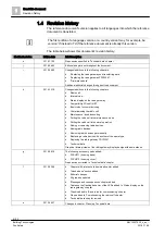
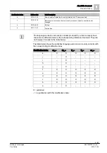
Page 9: ...6 22 Editing a 2011 11 01 First edition The language versions and country variants produced by a local company have the same modification index as the corresponding reference document They are not however included in the table below The table below shows the published language versions and country variants with the corresponding modification index Modification index en_ de_ fr_ it_ es_ k X X X X X...

Page 10: ...al dangers the type of danger or possible consequences measures and prohibitions examples of which are shown in the following table General danger Explosive atmosphere Voltage electric shock Laser light Battery Heat Signal word The signal word classifies the danger as defined in the following table Signal word Danger level DANGER DANGER identifies a dangerous situation which will result directly i...

Page 11: ...ry is shown as follows WARNING Nature and origin of the danger Consequences if the danger occurs Measures prohibitions for danger avoidance How possible damage to property is presented Information about possible damage to property is shown as follows NOTICE Nature and origin of the danger Consequences if the danger occurs Measures prohibitions for danger avoidance ...

Page 12: ...idance and supervision of a qualified electrician in accordance with the electrotechnical regulations Wherever possible disconnect products from the power supply when carrying out commissioning maintenance or repair work on them Lock volt free areas to prevent them being switched back on again by mistake Label the connection terminals with external voltage using a DANGER External voltage sign Rout...

Page 13: ... may be produced Before testing the remote transmission inform the corresponding alarm and fault signal receiving stations Modifications to the system design and the products Modifications to the system and to individual products may lead to faults malfunctioning and safety risks Written confirmation must be obtained from Siemens and the corresponding safety bodies for modifications or additions M...

Page 14: ... injury and damage to property in the event of a fire Read the Release Notes before you plan and or configure a fire detection installation Read the Release Notes before you carry out a firmware update to a fire detection installation NOTICE Incorrect planning and or configuration Important standards and specifications are not satisfied Fire detection installation is not accepted for commissioning...

Page 15: ...r supply for the radio gateway The areas that radio cells cover may overlap The radio cell may take the following formats Loop with a maximum of 32 addresses 30 addresses for radio devices and 2 addresses for the radio gateway or Stub with a maximum of 32 addresses 30 addresses for radio devices and 2 addresses for the radio gateway Observe the country specific regulations relating to the permitte...

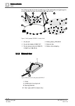
Page 16: ...C NET detector line Figure 1 Radio gateway FDCW241 on detector line 1 Radio cell 4 Radio gateway FDCW241 2 Radio fire detector FDOOT271 5 Detector line 3 Radio manual call point FDM273 FDM275 or FDM275 F 6 Radio cell overlapping 3 1 2 External view Figure 2 External view of radio gateway FDCW241 1 Screw A Unlocking for housing cover B Opening direction H1 Red green LED for detector line 2 4 5 3 6 ...

Page 17: ...ne 3 Detector line socket strip H2 Yellow LED for maintenance mode 4 Aerial H3 Yellow LED for reset 5 Opening for screw fastening H4 Yellow LED for radio cell 6 Socket for MCL USB adapter radio H5 Yellow LED for battery 7 Battery connector 3 pin H6 Green LED for connection to software tool FXS2061 8 Battery cable H7 Red LED for faults 9 Battery pack S1 Button for maintenance mode 10 Holder for bat...

Page 18: ... signaled and displayed on the control unit The following diagnosis levels are derived from the various control measurements in the radio cell Normal Battery low Battery empty Fault Diagnosis level Meaning Measures Normal No faults present The radio gateway is fully functional None Battery low The battery voltage is too low Battery pack replacement recommended Connect a new battery pack Battery em...

Page 19: ...et C NET detector line but not the exact location of the detector triggering the alarm Degraded mode operation on the FDnet C NET is not supported in the same way by all control panels The information in the List of compatibility and in the corresponding control panel documentation must be taken into account during project planning 3 2 3 Status display on the radio gateway The status is displayed ...

Page 20: ...stablished The radio gateway is now ready for operation H3 flashes yellow every second for 5 seconds Once the power supply has been connected and the indicator has flashed 5 times the radio gateway is ready for operation H4 flashes yellow every two seconds The radio cell is not yet ready for operation Not all the radio devices are being monitored yet or not all of them have been read in by the rad...

Page 21: ...r supply Power supply via the detector line For normal operation Power supply from battery pack BAT3 6 10 When the battery pack is supplying power the radio network remains active even if the detector line is switched off As a result wireless operation will occur when the detector line is switched on For commissioning the radio cell for the first time If the power supply via the detector line is i...

Page 22: ...way with power Lithium batteries BAT3 6 10 LI SOCl2 battery pack 3 6 V 10 Ah Batteries with battery cable Connector system with protection against polarity reversal Inscription field for commissioning date Compatible with Radio gateway FDCW241 Radio manual call point FDM273 Radio manual call point FDM275 Radio manual call point FDM275 F Radio fire detector FDOOT271 Order number S54370 Z11 A1 3 4 3...

Page 23: ...UZ227 For connecting FDnet C NET devices to a personal computer Signals can be transmitted to SWING radio devices via radio Interface converter for USB on MC link Compatible with Floor repeater terminal FT2010 Floor repeater display FT2011 Radio gateway FDCW221 and FDCW241 Detector exchanger and tester FDUD292 Intelligent detector tester FDUD293 Line tester FDUL221 Radio manual call point FDM27x R...

Page 24: ...eats this radio cell as a loop or a stub It is used for the Sinteso and Cerberus PRO product lines In the Planning document A6V10227631 you will find detailed information about the components of the radio fire detection system as well as the necessary devices and device combinations You will find more information in the List of compatibility 4 1 Compatibility FDnet C NET Compatible with control pa...

Page 25: ...information on this in the following table Radio device Detector line FDnet C NET FDCW241 MP4 IP4 FDOOT271 MP4 IP4 FDM273 MP4 IP4 FDM275 MP5 IP5 FDM275 F MP5 IP5 You will find detailed information in the List of compatibility Limitations Maximum 16 FDCW241 radio gateways per line Reduced if length of line is over 2 200 m as per Sinteso Quantities tool A6V10094878 or Cerberus PRO Quantities tool A6...

Page 26: ...accordance with the planning specifications make sure there is a wide radio range and that the housing can be accessed easily Make sure there is enough space for you to open the housing cover easily The housing may be installed in any appropriate position 2 Open the housing Remove the screw 2 A Using a screwdriver to press the lock 3 into the housing B and unlock the housing cover 1 Lift the housi...

Page 27: ...e for recesses 59 chapter One screw at the mounting point is sufficient for fixing in housing FDCH221 7 Fasten the cable using a cable tie as strain relief 4 8 Label the battery pack with the date 9 Insert the battery pack and check the position of the battery cable Do not connect the battery pack until you are ready to commission the radio cell The radio gateway is installed See also Commissionin...

Page 28: ...ateway in housing FDCH221 1 Break out the required cable entries 1 on the housing 2 Install the housing with screws 4 on a level surface 3 Insert the cables 2 If necessary fix the cables using M20 x 1 5 cable glands or use a different cable entry 4 Remove the housing cover from the radio gateway and dispose of it in an environmentally friendly manner 59 5 Install the radio gateway in the housing u...

Page 29: ...ect installation can take safety devices out of operation unbeknown to a layperson Once all the radio devices of a radio cell have been logged on to the radio gateway B in battery mode A the radio gateway can be connected to the FDnet C NET detector line C Figure 7 Connecting the radio cell to the detector line Figure 8 Connections on radio gateway FDCW241 1 detector line terminal strip A FC20xx F...

Page 30: ...ss FDCL221v as a line separator When you assign the connections you determine the order in which the devices are read in at the control panel The following topologies are possible Radio cell as LOOP Figure 9 Loop connection Radio cell as stub Figure 10 Stub connection only 1 2 X1 LOOP1_2 LOOP1_2 3 4 LOOP1_1 LOOP1_1 FC20xx FC720x 1 2 X1 LOOP1_2 LOOP1_2 3 4 LOOP1_1 LOOP1_1 _ _ _ _ _ _ FC20xx FC720x ...

Page 31: ...on of 1 5 2 5 mm Obtain a corresponding terminal from the customer for even larger cross sections The terminal can be positioned inside the housing The radio cell is in battery mode The detector line cable has a wire diameter of 0 2 1 5 mm The detector line terminal strip is not inserted The 2 pin terminal strip must not be connected 1 Wire the detector line terminal strip in accordance with the r...

Page 32: ...r line via the radio gateway The radio cell can be modified 6 1 Basic rules for commissioning Requirements for reliable radio device connections Radio cells whose areas of coverage overlap must not be in maintenance mode at the same time This means that you should only ever switch one radio cell at a time to maintenance mode Requirements for connecting the radio cell to the detector line The radio...

Page 33: ... devices one after the other The graphic below serves as an example of the correct sequence for commissioning radio devices Figure 12 Example Correct sequence for commissioning radio devices Radio gateway Radio device Commission the radio devices that are close to the radio gateway first Commission the radio devices that are furthest away from the radio gateway last Only commission the radio cell ...

Page 34: ...given time Start with the radio gateway Activate the radio gateway starting with the other radio devices Figure 13 Radio gateway FDCW241 H2 Yellow LED for maintenance mode S1 Button for maintenance mode H3 Yellow LED for power supply and reset S2 Reset button H4 Yellow LED for radio network The radio gateway is installed The radio gateway is not connected to the detector line The socket strips of ...

Page 35: ...tings press the new button on the radio device until the internal alarm indicator flashes red The radio device is set to the factory settings 6 Mount the radio device in the appropriate base FDOOT271 or in the appropriate housing FDM273 or back box FDM275 The search for the radio network starts During the search the internal alarm indicator briefly flashes green twice at an interval of 2 seconds O...

Page 36: ...d in at the fire control panel Two addresses are displayed for the radio gateway 1 Make a note of the sequence of the commissioned radio devices 2 Use the FXS2061 SWING Tool to back up the network file The procedure for backing up the network file is described in more detail in the User Guide SWING Tool FXS2061 in the Menu bar chapter You will find more information in the Changing and expanding th...

Page 37: ...l The radio gateway has been switched to maintenance mode The relevant zone has been switched off at the control panel You will find more information in the Changing and expanding the FDnet C NET detector line chapters of the following documents For control panels FC20xx Document 009052 For control panels FC72x Document A6V10210416 7 1 Establishing factory settings All settings are deleted and res...

Page 38: ...1 Release the battery connector 1 to interrupt the power supply 2 Wait approx 10 seconds Any residual voltage that was present is dissipated 3 Press and hold button S2 4 Connect the battery connector 1 to establish the power supply 5 Release button S2 6 LED H3 flashes rapidly 40 times for 20 seconds After this the radio gateway is set to the factory settings 7 Re establish the other connections th...

Page 39: ...e radio gateway is in normal operation 1 Switch off the relevant zone on the station LED H2 is not flashing 2 Press and hold button S1 for at least 2 seconds until LED H2 flashes The radio gateway and its radio cell are in maintenance mode LED H2 flashes at 1 second intervals The radio devices can now be logged on You will find more information in the Changing and expanding the FDnet C NET detecto...

Page 40: ...e radio gateway is open The process of logging radio devices on to the radio gateway is complete 1 Check LED H2 In maintenance mode LED H2 flashes 2 Press and hold button S1 for at least 2 seconds LED H2 goes out The radio cell is in normal operation If necessary check the station settings You will find more information in the Changing and expanding the FDnet C NET detector line chapters of the fo...

Page 41: ...anels FC20xx Document 009052 For control panels FC72x Document A6V10210416 See also Connecting the radio gateway 29 Applicable documents 7 7 4 1 Adding radio devices The procedure for adding radio devices on a detector line is no different to the one used for adding wired devices The relevant fire detection system documents also apply to the SWING radio fire detection system Wait until one radio d...

Page 42: ...ings press the new button on the radio device until the internal alarm indicator flashes red The radio device is set to the factory settings 7 Mount the radio device in the appropriate base FDOOT271 or in the appropriate housing FDM273 or back box FDM275 The search for the radio network starts During the search the internal alarm indicator briefly flashes green twice at an interval of 2 seconds On...

Page 43: ...etected fire When parts of the system are switched off they are not monitored and no fire alarm signals are issued for them Keep the amount of time during which parts are switched off to a minimum Put the intended safety measures in place NOTICE Do not remove multiple radio devices at the same time This may cause other radio devices to lose their connection to the radio gateway and be displayed as...

Page 44: ...teway FDCW241 H2 Yellow LED for maintenance mode S1 Button for maintenance mode H3 Yellow LED for power supply and reset S2 Reset button H4 Yellow LED for radio network Proceed as follows to remove a radio device You have a device location plan showing the locations of the radio devices in the radio cell It is possible to access the station 1 Proceed according to chapter Changing and expanding the...

Page 45: ...ulations and laws See also chapter Basic principles for replacing the battery pack 51 The radio gateway registers the radio device as missing after a maximum of 5 minutes LED H4 flashes 9 When LED H4 flashes press and hold button S1 for at least 2 seconds The radio cell switches to normal operation The radio gateway deletes the missing radio device from its memory 10 Follow the same steps to remov...

Page 46: ...cing one device before you start replacing the next one This will ensure that the site configuration does not change Figure 19 Radio gateway FDCW241 H2 Yellow LED for maintenance mode S1 Button for maintenance mode H3 Yellow LED for power supply and reset S2 Reset button H4 Yellow LED for radio network Proceed as follows to replace the radio device The housing for the radio gateway is open 1 Proce...

Page 47: ...rm indicator flashes red The radio device is set to the factory settings 10 Install the radio device in the appropriate base FDOOT271 or the appropriate housing FDM273 The search for the radio network starts During the search the internal alarm indicator briefly flashes green twice at an interval of 2 seconds Once the radio device has successfully been logged on to the radio gateway the network se...

Page 48: ...ector line terminal strip is connected according to chapter Connecting the radio gateway 29 All radio devices are logged on to the radio gateway The radio gateway is set to normal operation 1 Connect the radio gateway and the detector line by inserting the detector line terminal strip into the radio gateway 2 Close the radio gateway housing 3 Switch the detector line on The radio gateway is now co...

Page 49: ...ion installation as the old radio gateway uses the same net ID as the new radio gateway After it has been reset to the factory settings the old radio gateway can be used again For radio gateways with ES 15 the old radio gateway is inoperative after the replacement Radio gateways with ES 15 may only be replaced by another radio gateway with ES 15 For radio gateways with ES 15 the old radio gateway ...

Page 50: ... gateway 2 Confirm the successful data transfer with OK 3 The new radio gateway automatically has the net ID of the old radio gateway 4 Check whether the LED H4 is flashing 5 Overwrite the net ID of the new radio gateway with the net ID of the old radio gateway on the type plate 6 Wait until LED H4 stops flashing This can take up to 30 minutes depending on the size of the radio cell 7 Install the ...

Page 51: ...k Do not damage or dismantle the battery pack Do not heat the battery pack to more than 100 C WARNING Disposing of damaged or leaky battery packs Lithium can burn the skin and produce toxic vapors Avoid direct contact with the body Wear appropriate protective clothing safety gloves safety goggles etc Use appropriate means of transportation to move damaged batteries around Do not breathe in vapors ...

Page 52: ...attery pack H1 Red green LED for detector line 3 Battery connector 3 pin H5 LED amber The radio gateway is connected to the FDnet C NET and is being supplied with power This connection must not be interrupted while the battery is being replaced You have a new undamaged battery pack BAT3 6 10 to hand 1 Open the housing cover 2 Release the battery connector 3 3 Push the holder 1 to the side 4 Remove...

Page 53: ...e is configured as saving the message must be confirmed each time it occurs The message remains on the display until it is confirmed In countries where this message is configured as non saving the message stops being shown on the display once the radio device becomes available again in the radio cell The radio device is only able to detect fire again and forward the alarm once the device is availa...

Page 54: ...p 1 mA 0 6 25 mA Maximum current connection factor 16 Quiescent current connection factor 6 Address connection factor 2 n 1 n number of radio devices Separator connector factor 1 Protocol FDnet C NET Compatibility See List of compatibility Design Inherently short circuit proof Protected against polarity reversal Protected against overvoltage Line separator Line voltage Nominal DC 32 V Vnom Minimum...

Page 55: ...Hz in band 48 49 50 54b and 56b Channel grid 50 kHz Number of channels 27 in 868 MHz band 20 in 433 MHz band Transmitting power 10 mW ERP in band 44b 45b and 49 Type 10 max 25 mW ERP in band 48 50 54b and 56b Range See document A6V10227631 2013 752 EU according Official Journal of the European Union COMMISSION IMPLEMENTING DECISION of 11 December 2013 amending Decision 2006 771 EC on harmonisation...

Page 56: ...5 34 868 875 162 433 875 36 868 925 164 433 925 38 868 975 166 433 975 40 869 025 168 434 025 42 869 075 170 434 075 44 869 125 172 434 125 46 869 175 174 434 175 56 869 425 176 434 225 58 869 475 178 434 275 60 869 525 180 434 325 62 869 575 182 434 375 64 869 625 68 869 725 70 869 775 72 869 825 74 869 875 76 869 925 78 869 975 Battery pack BAT3 6 10 Lithium battery pack BAT3 6 10 LI SOCl2 batte...

Page 57: ... socket Ambient conditions Operating temperature 10 55 C Storage temperature 30 75 C Air humidity 95 rel Protection category IEC 60529 In housing FDCH221 IP40 IP65 Electromagnetic compatibility 100 kHz 2 5 GHz 30 V m Mechanical data Weight without battery pack 0 154 kg Housing material Acrylonitrile butadiene styrene ABS Color RAL 9010 pure white Standards European standards EN 54 17 EN 54 18 EN 5...

Page 58: ...Specifications Dimensions 8 58 62 Building Technologies A6V10227639_k_en_ Fire Safety 2016 11 28 8 2 Dimensions Radio gateway FDCW241 167 89 28 ...

Page 59: ...aken Use of reusable materials Use of halogen free plastics Electronic parts and synthetic materials can be separated Larger plastic parts are labeled according to ISO 11469 and ISO 1043 The plastics can be separated and recycled on this basis Electronic parts and batteries must not be disposed of with domestic waste Take electronic parts and batteries to local collection points or recycling cente...

Page 60: ...nit comprising all radio devices connected to the radio gateway Radio device Any device that the radio gateway monitors Radio network Within a radio cell bidirectional radio connections are established between the radio devices Together with the radio gateway connections these create a radio network ...

Page 61: ...anel failure 19 Diagnosis levels Overview 18 Disposal 59 Download center URL 7 E Environmental compatibility 59 EU directives 54 F Fire control panel failure Degraded mode operation 19 I Indicators 17 LED 19 Installing housing FDCH221 28 Intended use 5 L List of compatibility 7 19 25 54 M Mounting Attaching at the installation location 26 Electrical connection 29 O Original language 6 Overview Ext...

Page 62: ...al Headquarters Gubelstrasse 22 CH 6301 Zug 41 41 724 24 24 www siemens com buildingtechnologies Siemens Switzerland Ltd 2011 Technical specifications and availability subject to change without notice Document ID A6V10227639_k_en_ Manual FD20 FD720 Edition 2016 11 28 Register 5 ...

Reviews: