background image

Instruction Manual September 2003

ILE-37

milltronics

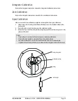
Summary of Contents for milltronics ILE-37

Page 1: ...Instruction Manual September 2003 ILE 37 milltronics ...

Page 2: ...n electronic version We encourage users to purchase authorized bound manuals or to view electronic versions as designed and authored by Siemens Milltronics Process Instruments Inc Siemens Milltronics Process Instruments Inc will not be responsible for the contents of partial or whole reproductions of either bound or electronic versions While we have verified the contents of this manual for agreeme...

Page 3: ...Non Hazardous Unit with Remote Located LVDT Conditioner Card 8 Calibration 9 LVDT Output 9 Zero Adjustment if required 9 Span Test 10 Sensing Head Level Test 10 Integrator Calibration 11 Zero Calibration 11 Span Calibration 11 Maintenance and Spare Parts 12 Maintenance 12 Typical Maintenance Program 12 Spare Parts 12 Unit Repair and Excluded Liability 12 Range Springs 13 Range Spring Removal 13 Ra...

Page 4: ...ii ...

Page 5: ...impact force of the material deflecting the sensing plate displaces the core of the sensing head LVDT linear variable differential transformer The LVDT output signal is proportional to material flowrate A viscous fluid damper prevents oscillation of the mechanism and provides mechanical damping of pulsating material flow The ILE 37 sensing head is used with Milltronics E 40 general purpose C 40 co...

Page 6: ...rator Repeatability 0 2 Construction dust tight cast aluminum frame with fiberglass rear cover Mounting side mount or base mount to suit application Sensor Type LVDT linear variable differential transformer LVDT Excitation 2 50 V AC 2 9 kHz supplied byintegrator or LVDT conditioner card LVDT Output 0 0 75 V AC 2 9 kHz Damping Fluid 1 100 cm2 s 100 10 000 cs silicone Dow Corning 200 recommended Opt...

Page 7: ... mV DC to Siemens Milltronics integrator maximum 300 m 1000 ft separation between conditioner card and integrator Approvals CE Enclosure NEMA 4 remote mounted unit Cable For connection between LVDT Conditioner Card and Integrator Belden 1 8404 4 conductor shielded 20 AWG 0 5 mm2 or equivalent 150 m 500 ft maximum Belden 9260 6 conductor shielded 20 AWG 0 5 mm2 or equivalent 300 m 1000 ft maximum F...

Page 8: ...en the four ILE 37 mounting bolts 3 Place a spirit level on the flat top of the ILE 37 frame adjust the sensing head level by rotating it and retighten the mounting bolts Base Mount 1 With the flowmeter housing installed mount the ILE 37 to a rigid support structure 2 With the outer gasket in place bolt the ILE 37 to the housing 3 Adjust the sensing head levelling hardware provided to establish le...

Page 9: ...by a spring 2 If necessary top up the damper to near overflowing with the damping fluid supplied 3 Store the damper cover shipping screws remaining damper fluid and filler bottle for future use Note Ensure the slot in the end of the shaft mates with the roll pin in the back of the socket Note The damper must be full and free of air bubbles with the damper cover in the UP position during flowmeter ...

Page 10: ...VDT Conditioner Card See note below for Encapsulated Hazardous rated LVDT color codes Note Ground shield at Integrator only to LVDT G R N B L K Y E L B L U R E D S I G C O M E X C E X C to Integrator sensing head terminal block For Encapsulated LVDT hazardous YEL WHITE BLU ORANGE GRN YELLOW cable clamp ...

Page 11: ...ock marked Integrator EXC from SF500 terminal 13 to conditioner terminal block marked Integrator EXC For further connection information on specific LVDTs consult Siemens Milltronics Note Shields are common but not grounded to chassis Run cable shields through SHLD terminals and ground at Integrator only 11 14 1 2 11 1 6 12 2 7 13 3 8 14 15 16 17 4 9 5 10 18 V S S V SHLD LOAD CELL EXCITATION LCA LC...

Page 12: ... further connection information on specific LVDTs consult Siemens Milltronics Note Shields are common but not grounded to chassis Run cable shields through SHLD terminals and ground at Integrator only 11 14 1 2 11 1 6 12 2 7 13 3 8 14 15 16 17 4 9 5 10 18 V S S V SHLD LOAD CELL EXCITATION LCA LCA LCB LCB SHLD LCC SIG LCC COM LCD CNST LCD SHLD LOAD CELL INPUTS E X C E X C E X C E X C C O M S I G C ...

Page 13: ... 40 flowmeter is 500 grams Test Rate 500 grams 65 grams TPH 7 65 TPH LVDT Output Zero Adjustment if required 1 Connect a voltmeter across the LVDT green and yellow or yellow and white hazardous LVDT wires 2 With no load applied to the sensing plate observe the V AC reading on the voltmeter If the LVDT output is 0 10 0 05 V AC skip to Span Test otherwise proceed as follows a Loosen the locknut on t...

Page 14: ...t weight directly off the sensing plate 2 Check to ensure that the LVDT output does not change by more than 0 01 V AC Note The LVDT core must not contact the inside of the LVDT over the range of core travel The actual LVDT core travel during this procedure is less than 3 mm 1 8 Note If the change is greater than 0 01 V AC adjust the sensing head level refer to Installation on page 4 until the chan...

Page 15: ... monofilament fishing line or fine flexible cable to the test weight 2 Route the other end of the string over the calibration pulley 3 Attach the free end of the string to the string fixing bolt Ensure the string rests in the groove of the bolt Note Ensure there is no material flow during zero and span calibrations Ensure the test weight is suspended free of any obstructions Accurate calibration i...

Page 16: ...ering information Unit Repair and Excluded Liability All changes and repairs must be done by qualified personnel and applicable safety regulations must be followed Please note the following The user is responsible for all changes and repairs made to the device All new components must be provided by Siemens Milltronics Process Instruments Inc Restrict repair to faulty components only Do not re use ...

Page 17: ... rate of the flowmeter application change it may be necessary to select and install another range spring to obtain the optimum moving beam travel LVDT output range Range Spring Removal 1 Loosen the range spring locknut 2 Remove the range spring mounting bolt and three flange mounting bolts 3 Remove the range spring from the range spring assembly Range Spring Replacement 1 Install the new range spr...

Page 18: ...iscous damper cover in shipping position Refer to INSTALLATION Viscous Damper Integrator not prepared for operation Program and calibrate the integrator Span adjustment does not have enough range Range spring not suited to application Refer to RANGE SPRINGS Measurement results are not repeatable Sensing head not level Refer to INSTALLATION and CALIBRATION Sensing Head Level Test Moving beam travel...

Page 19: ...oes not touch the damper cylinder wall at any flow rate the LVDT core does not touch the inside of the LVDT at any flow rate the viscous damper fluid is free of large air bubbles and the fluid level is correct the range spring operates in compression from 0 100 flow rate the sensing head leaf springs are in good condition If the test weight linearity test is successful yet actual material test res...

Page 20: ...g head mounting hole to the flowguide centerline 2 Ensure that the outer gasket seal to the flowmeter housing wall is dust tight see Note 1 outer gasket as required 250 mm 9 84 B C D 225 mm dia 8 85 50 o 40 o sensing pate 305 mm 12 327 mm 12 88 fiberglass cover conduit entry 1 2 NPT internal 50 o 35 o FIG 1 ...

Page 21: ... Flowmeter housing 3 Ensure that the outer gasket seal to the Flowmeter housing wall is dust tight outer gasket conduit entry 1 2 NPT internal fiberglass cover 280 mm 11 256 mm 10 06 50 mm 1 97 90 mm 3 54 70 mm 2 76 290 mm 11 5 30 mm 1 18 sensing plate see Note 1 8 mm 0 31 dia 18 bolts on 360 mm 14 17 B D C as required 385 mm 15 12 260 mm 10 25 180 mm 7 09 support plate customer supplied 10 mm 0 3...

Page 22: ... 38 67 35 47 35 63 52 4 21 18 16 12 13 35 32 INSIDE 37 2 32A 39 48 26 75 38 67 10 34 38 11 67 38 56 OR OR OR 27 80 81 52 82 52 45 42 52 48 17 24 25 23 53 64 72 73 74 1 3 39 52 69 52 36 7 56 57 6 9 17 22 46 40 52 59 57 14 28 30 78 60 58 55 41 79 FIG 3A ...

Page 23: ... 15 not applicable 16 Damper Window 17 Damper Cover 18 Damper Piston 19 not applicable 20 Bushing Locknut 2 21 O Ring 3 1 4 x 3 1 2 x 1 8 22 O Ring 1 3 8 x 1 5 8 x 1 8 23 Hinge Spring Spacer 8 24 Hinge Spring Spacer 8 25 Hinge Spring 0 3mm 25mm 2 26 or 27 Hinge Spring 0 55mm 25mm or 1 0mm 25mm 2 28 or 30 Diaphragm silicone or neoprene 31 not applicable 32 VDT 32A LVDT Core 33 Pivot Bearing 2 34 Lo...

Page 24: ...nless 2 58 Inner Gasket Ring base mount only 59 Damper Spring 60 Outer Gasket Ring base mount only Identification Description 61 not applicable 62 Teflon Washer 63 Nut M4 stainless 2 64 Split Lock Washer M3 stainless 2 65 not applicable 66 Washer M5 stainless 2 67 Split Lock Washer M5 stainless 6 68 not applicable 69 Cap Screw M3 x 20 mm stainless 2 70 O Ring 7 16 x 5 8 x 3 32 71 not applicable 72...

Page 25: ...Notes ...

Page 26: ...Notes ...

Page 27: ......

Page 28: ...s Process Instruments Inc 1954Technology Drive P O Box 4225 Peterborough ON Canada K9J 7B1 Tel 705 745 2431 Fax 705 741 0466 Email techpubs siemens milltronics com Siemens Milltronics Process Instruments Inc 2003 Subject to change without prior notice Printed in Canada ...

Reviews: