Installation Instructions
Document No. 545-407
February 7, 2003
MMI Extension Cable
Item Number: 545-407-04, Rev. 010
Page 1 of 2
Product Description
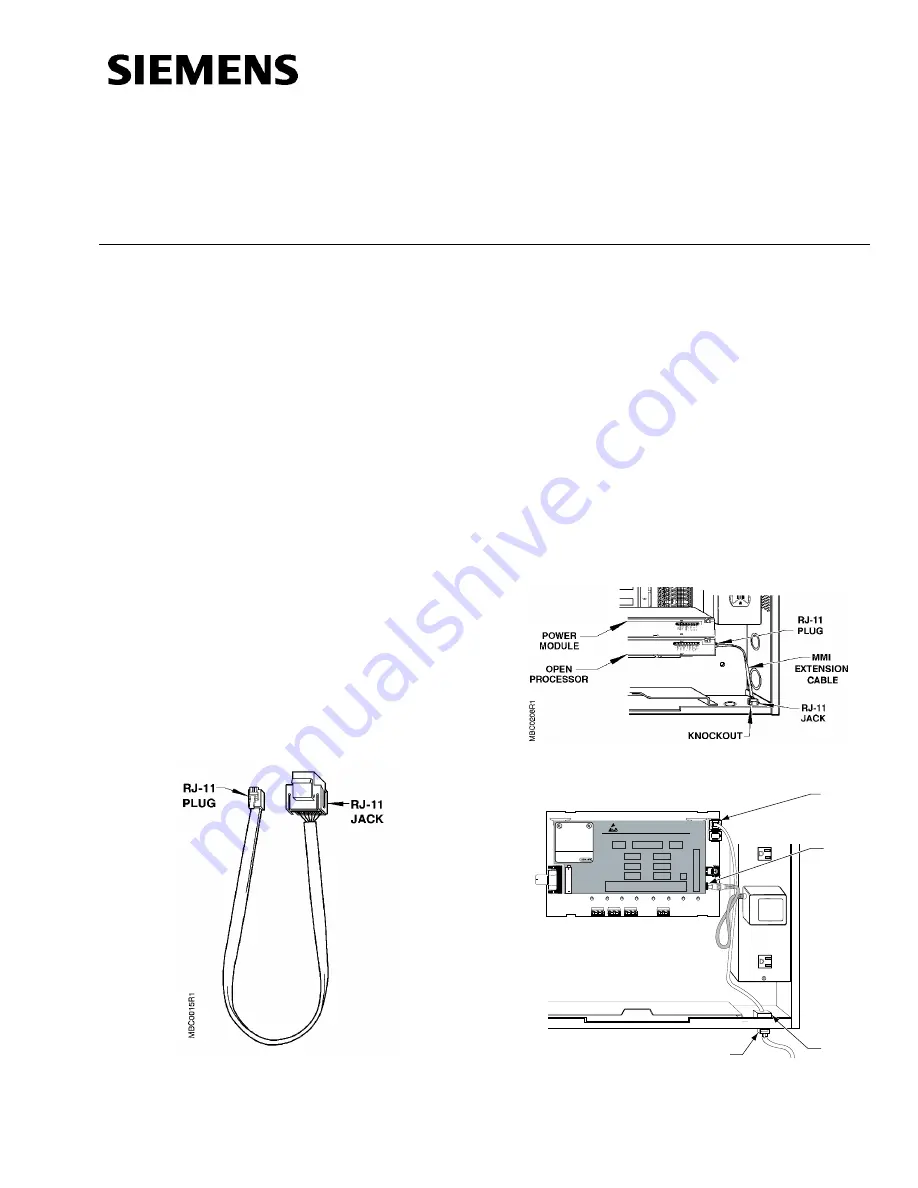
The MMI Extension Cable (Figure 1) is an accessory
that allows you to connect a computer to an Open
Processor, Controller Module, or Gateway Module
and use the computer when the enclosure door is
closed or locked. The cable can be used with a
Modular Building Controller (MBC), Remote Building
Controller (RBC), or the Controller Board of a Floor
Level Network (FLN) Controller.
NOTE: See the following manuals for further
information about system installation and
programming constraints:
•
Smoke Control Application and
Engineering Manual (125-1806)
•
APOGEE Automation Technical
Reference on InfoLink
Product Numbers
545-712
MMI Extension Cable Assembly
(includes RJ-11 plug and RJ-11 jack)
Required Tools
•
Flat-blade screwdriver
Figure 1. MMI Extension Cable.
Expected Installation Time
3 minutes
Prerequisites
•
None
Installation
1.
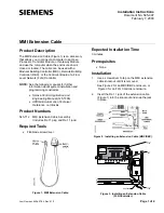
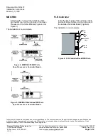
Use a screwdriver to tap on the MMI extension
cable knockout until it is removed.
See Figure 2 for an MBC/RBC enclosure, or
Figure 3 for an FLN Controller enclosure.
2.
Insert the RJ-11 jack of the extension cable
(Figure 1) into the knockout and snap the jack
in place.
Figure 2. Installing an Extension Cable (MBC/RBC).
FLN0018R1
F
L
N
1
F
L
N
2
F
L
N
3
B
L
N
-
S
+
-
S
+
-
S
+
-
S
+
12
VDC
RJ-11
PLUG
RJ-11
PLUG
KNOCKOUT
MMI
Modem
Port
MMI
Port
Controller Board
BPS (Bits per second)
BLN #
Field Panel No./Name
Memory
FLN1
FLN2
FLN3
MMI
Modem
MMI
BLN
WARNING:
Power must be ON
when replacing the
battery, otherwise
the cabinet will
coldstart.
TIU
Enabled
Product Part No.
545-793
Refer to Installation Instructions, Part No.
545-429
Adher
e Bar Code Label in this space
.
Underwriters Laboratories Inc. ®
LISTED
SMOKE CONTROL SYSTEM EQUIPMENT SUBASSEMBLY.
Also suitable for use as:
ENERGY MANAGEMENT SUBASSEMBLY.
Also suitable for use as:
SIGNAL SYSTEM UNIT SUBASSEMBLY.
Also suitable for use as:
PROCESS MANAGEMENT EQUIPMENT SUBASSEMBLY.
Issue No.
For use with System 600 as part of an engineered
smoke control system in accordance with NFPA 92A.
C
¤
¤
WARNING: Risk of static discharge.
Turn OFF power before removing or servicing
boards. Use ESD wrist strap when servicing unit.
Figure 3. Installing an Extension Cable
(FLN Controller).


