
8AA9992 - D1 - 10/11/2000 - UK -
Fig. 1
Fig. 2b
Fig. 3
Fig. 2a
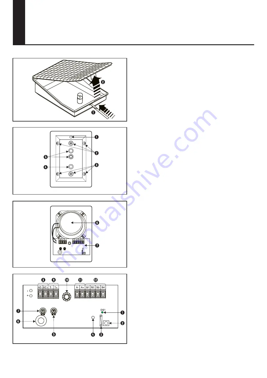
3.2 Product overview (Fig. 2)
- Knockouts
Q
,
T
for cable inlet.
- Knockouts
W
,
E
for attachment of housing.
- Knockout
R
back tamper contact.
- Speaker
Y
.
- WMC 12 circuit board
U
.
3.3 WMC 12 circuit board (Fig. 3)
- E-Bus connection
}
.
- Audio connection
{
to central control unit.
- Audio connection
I
to WAC 11 or WAS 11.
- Tamper input
O
for WAC 11 or WAS 11.
- LED
Q
, flashes when E-Bus is o.k.
- LED
R
, flashes to outside during monitoring (microphone
active).
- Address button
W
.
- Switch
E
for "microphone active" LED.
- Tamper switch
P
.
- Microphone
Y
.
- Potentiometer
T
for speaker volume.
- Potentiometer
U
for microphone sensitivity.
1. Product description
The WAC 12 is used to verify audio alarms. It is fitted with a
speaker and microphone. It can be controlled through the E-
Bus, with the audio signal connected to the central control unit
via an audio module (e.g. WMA 11). The WAC 12 also serves as
a master for the unaddressable WAC 11 and WAS 11.
2. Supply package
The WAC 12 UK package contains the following
- One WAC 12
- One WLC 12 UK language kit complete with:
- Installation instructions.
3. Mounting instructions
The WAC 12 is designed for mounting in dry indoor rooms.
To ensure good acoustics, note the following points.
- Mount 2 to 2.5 m above floor level.
- Maintain adequate distance from noise sources (ven ti la tion
openings, fans etc.).
- Direct towards the centre of the space to be monitored.
- Do not mount on vibrating surfaces.
- The maximum length of the audio connection between the
WAC 12 and central control unit is 200 m.
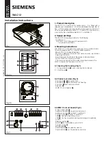
3.1 Opening the housing (Fig.1)
1 - Using screwdriver
Q
, press locking tab to release.
2 - Lift off cover
W
.
s
Installation Instructions
WAC 12
WLC 12 UK
20 800 042.0-010


