background image

GUIDA TECNICA

Istruzione d'uso
Montaggio
Manutenzione

Istructions for Use
Assembly
Maintenance

Bedienungsanweisung
Montage
Wartung

Utilisation
Assemblage
Entretien

User's Manual - Technische Anleitung
Guide Technique

Pasticceria

KAPPA

KPPS 0710

Pastry display unit - Konditoreivitrine - Vitrine pâtisserie

Summary of Contents for KAPPA

Page 1: ...ione Istructions for Use Assembly Maintenance Bedienungsanweisung Montage Wartung Utilisation Assemblage Entretien User s Manual Technische Anleitung Guide Technique Pasticceria KAPPA KPPS 0710 Pastry display unit Konditoreivitrine Vitrine pâtisserie ...

Page 2: ......

Page 3: ...o de série ANNO DI COSTRUZIONE Year of Manufacture Baujahr Année de construction Società Industria Frigoriferi e Arredamenti S p a Via Nazionale 15 19 61022 COLBORDOLO PU ITALY Tel 39 0721 4741 Fax 39 0721 497507 info sifaspa it www sifaspa it ...

Page 4: ... used Ignoring the above recommendations can com promise operator safety SIMBOLOGIA 1 Questo simbolo indica pericolo e verrà utilizzato tutte le volte che sia coinvolta la sicurezza dell operatore 2 Questo simbolo indica cautela e vuole ri chiamare l attenzione su operazioni di vitale importanza per un funzionamento corretto e duraturo della macchina 3 La presenza di questo simbolo sulla mac china...

Page 5: ...l emploi des pièces détachées originales Le non respect des instructions ci dessus peut compromettre la sécurité de l opérateur SYMBOLIK 1 Diese Symbol bedeutet Gefahr und wird immer dann verwendet wenn die Sicherheit des Bedieners gefährdet ist 2 Diese Symbol bedeutet Vorsicht und lenkt die Aufmerksamkeit auf Vorgänge die für eine korrekte und dauerhafte Funktionstüchtigkeit der Maschine von grun...

Page 6: ...i al precedente art 1 e di cui alle clausole del frontespizio della conferma d ordine GENERAL CONDITIONS OF SALE These general conditions of sale shall apply to all supply relationships between the parties hereto as from January 1 2005 and shall annul and supersede any and all previous understandings between the parties Such conditions shall be regarded as fully accepted by the Purchaser and there...

Page 7: ...GÉNÉRALES DE VENTE Ces conditions générales de vente régissent toutes les fournitures effectuées à compter du 1er janvier 2005 et annulent tout accord passé précédemment entre les parties Elles sont considérées comme intégralement acceptées par l acheteur Toute commande envoyée à la société Sifa spa sera par conséquent régie par les conditions suivantes Art 1 Objet Paiement Livraison Transport La ...

Page 8: ... obbligazioni contrattualmente assunte the header of the order confirmation or in case of a hire purchase should it delay or fail to make even one payment of a value exceeding one eighth of the price due SIFAS p A pursuant to and for the pur poses of article 1456 of the Italian Civil Code shall be entitled to terminate this contractual agreement by registered letter with delivery confirmation to the...

Page 9: ...de commande ou en cas d absence ou de retard de paiement si un paiement échelonné est prévu même d un seul versement qui dépasserait un huitième du prix total la société Sifa S p a pourra résilier en application de l article 1456 du code civil ce règlement contractuel par envoi au client d une lettre recommandée avec accusé de réception en conservant à titre d indemnité sans préjudice de tous domm...

Page 10: ...ctive in the event the Purchaser fails to comply with one or more of its obligations hereunder Art 5 Disputes and Jurisdiction Any dispute arising out of or in connection with the drawing up the validity the performance or the interpretation of thisAgreement shall be submitted to the exclusive jurisdiction of the Court of Pesaro with the express exclusion of any other court The parties may refer e...

Page 11: ... Käufer der klagende Teil ist dann ist die Klage der zuvor zu erfolgenden Zahlung der geschuldeten Summen nachgeordnet gemäß der Klausel solve et repete l arrêt des appareils ou en cas de dommages subis par des personnes ou des biens et que la garantie ne s applique pas en cas d inexécution de la part de l acheteur d une ou de plusieurs obligations prévues au contrat Art 5 Attribution de juridicti...

Page 12: ...NE PLAFONIERA 74 5 4 SOSTITUZIONE DEI VENTILATORI PER LA CIRCOLAZIONE FORZATA 76 6 ANOMALIE DI FUNZIONAMENTO 78 7 CATALOGO RICAMBI 86 Contents 1 WITH EXTRACTABLE DRAWERS 14 1 1 DESCRIPTION OF DISPLAY CABINET 14 1 2 APPLIED REGULATIONS 18 1 3 OPERATOR AREA 20 1 4 MODELS 20 1 5 PRODUCT IDENTIFICATION 22 1 6 WEIGHTS AND OVERALL DIMENSIONS 22 1 7 TECHNICAL DETAILS 24 2 INSTALLATION 26 2 1 TRANSPORT 26...

Page 13: ...NT DES SURFACES VITREES 71 5 3 REMPLACEMENT DU PLAFONNIER 75 5 4 REMPLACEMENT DES VENTILATEURS POUR LA CIRCULATION FORCEE 77 6 ANOMALIES DE FONCTIONNEMENT 84 7 CATALOGUE DES PIECES DETACHEES 87 Inhaltsverzeichnis 1 TECHNISCHE ANGABEN 15 1 1 BESCHREIBUNG DER KÜHLVITRINE 15 1 2 ANGEWENDETE NORMEN 19 1 3 ARBEITSPLATZ 21 1 4 MODELLE 21 1 5 IDENTIFIZIERUNG 23 1 6 AUSMASSE UND GEWICHTE 23 1 7 TECHNISCHE...

Page 14: ...o inferiori ai valori stabiliti e preimpostati Un display digitale gestito dalla centralina mostra la tem 1 WITH EXTRACTABLE DRAWERS 1 1 DESCRIPTION OF DISPLAY CABINET Modules for ducting available in 100 150 200 and 250 cm lengths for the version with a large extractable drawer and 100 150 200 250 cm spherical modules A45 and B45 in the fixed shelf version The base structure consists of metal pipe...

Page 15: ... zeigt die in der Vitrine gemessene Temperatur und befindet sich an der Frontblende 1 SPECIFICATIONS TECHNIQUES 1 1 DESCRIPTION DE LA VITRINE Modules canalisables prévus en 100 150 200 et 250 cm de long dans la version à grands tiroirs extractibles et en 100 150 200 250 cm et modules arrondis A45 et B45 dans la version à plan d exposition fixe La structure du soubassement est formée de tubes métal l...

Page 16: ... miniplafoniere in alluminio con led di potenza al suo interno inserite sia sul cappello superiore che in ognuna delle mensole intermedie controlled by the control unit indicates the temperature inside the display unit Two types of refrigeration are available ventilated and static Ventilated refrigeration takes place by means of magnetic levitation fans powered at 12 V d c The rotation speed of th...

Page 17: ...heur numérique situé sur le bandeau de façade et géré par la centrale indique la température détectée dans la vitrine Deux types de réfrigération sont disponibles ventilée ou statique La réfrigération ventilée est obtenue par des turbines à lévi tation magnétique alimentées en courant continu 12V La vitesse de rotation de ces turbines qui est programmée sur des valeurs testées en chambre climatiqu...

Page 18: ... esposizione e vendita Parte 2 Classificazione requisiti e condizioni di prova Classe climatica A A further shelf at the rear is available as standard only in modules with the large drawer it cannot be fitted with a light fixture The rear closure mechanism is only available with sliding Plexiglas panels A fixed double glazed glass dividing panel should be installed between ventilated display units and...

Page 19: ...DUKTS UNI EN ISO 23953 2 2006 Verkaufskühlmöbel Teil 2 Klassifizierung Anforderungen und Prüfbedingungen Klimaklasse A diaires Une autre étagère placée à l arrière est disponible de série mais uniquement pour les modules à grand tiroir et elle ne peut pas être équipée de plafonnier La fermeture arrière est disponible uniquement avec coulissants en plexiglas Lors de la juxtaposition de vitrines vent...

Page 20: ...arecchi bagno maria elettrici per uso collettivo EN 60335 2 49 Parte II Norme particolari per armadi caldi per uso collettivo 1 2 APPLIED REGULATIONS The display unit fully conforms to the electromagnetic compatibility directive 2004 108 EEC and the following regulations EN 61000 3 2 Part 3 Limits Section 2 Limits for harmonic current emissions equip ment with an input current of 16 A per phase EN...

Page 21: ... particulières pour les appareils bain marie électriques à usage collectif EN 60335 2 49 Partie II Règles particulières pour les armoires chauffan tes électriques à usage collectif 1 2 ANGEWENDETE NORMEN Die Vitrine entspricht der Richtlinie 2004 108 EWG für Elektromagnetische Verträglichkeit sowie den Normen EN 61000 3 2 Teil 3 Grenzenwerte Abschnitt 2 Grenzwerte für Rückwirkungen in Stromver sor...

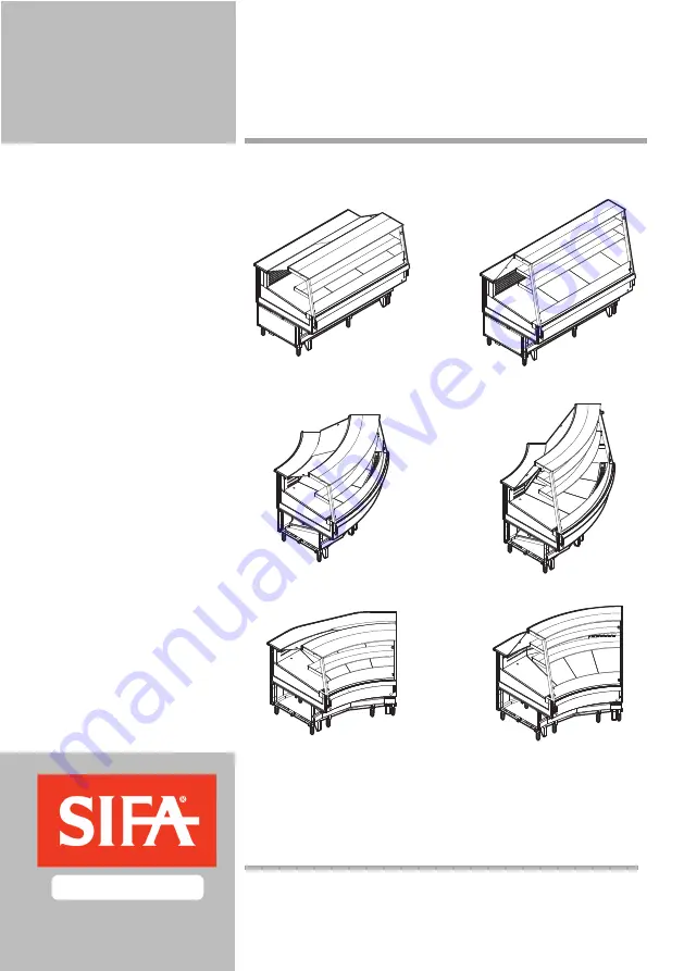
Page 22: ...so inclinato pos D Modello angolare aperto denominato B45 con piano fisso inclinato pos E 1 3 OPERATOR AREA The display unit operator area is behind the unit itself and contains the start and temperature adjustment controls In this area there is also an opening for access to the unit display top 1 4 MODELS All available models look the same but differ in length and height from the floor 118 cm and 1...

Page 23: ...B45 genannt mit geneigter Festo berfläche Stell E 1 3 POSITION DE TRAVAIL La zone de service de la vitrine se trouve sur la partie arrière de cette dernière où se trouvent les commandes de mise en marche et de régulation de la température et où l on trouve l ouverture d accès au plan d exposition 1 4 MODELES Tous les modèles disponibles ont la même esthétique mais sont différents au point de vue lo...

Page 24: ...e found fixed to the plate on the back operator s side of the unit Fig N 5 1 6 DIMENSIONI Dl INGOMBRO E PESI I valori sono riportati in tabella TN 1 1 6 WEIGHTS AND OVERALL DIMENSIONS The values are shown in Table TN 1 A B1 C B2 A B1 C A B1 B2 C fluido XXXXXX 88 8 88 C espansione classe C umidità KCAL H W V Hz W KG XXXXXXXXXXXXXXXXXXXXXXXXXXXXXXXXXXXXXX SIFA S p A Via nazionale 15 19 61022 COLBORDO...

Page 25: ...i se trouve sur la plaquette fixée sur le côté arrière côté service de la vitrine Fig N 5 1 6 DIMENSIONS D ENCOMBREMENT ET POIDS Les valeurs sont reportées dans le Tableau TN 1 1 6 AUSMASSE UND GEWICHTE Die Werte sind in Tabelle TN 1 angegeben Modello Unit Modell Modèle 100 150 200 250 A45 B45 A mm 1180 1500 1180 1500 1180 1500 1180 1500 1180 1500 1180 1500 B1 mm 1000 1000 1000 1000 1000 1000 1000 ...

Page 26: ...0 50hz 208 240 60hz 2 6 C 35 6 43 F 4 5 446 10 C 1522 14 F 287 1 9 150 7 3 581 10 C 1983 14 F 595 3 200 8 8 701 10 C 2393 14 F 735 3 7 250 12 1 944 10 C 3223 14 F 900 4 5 A45 6 2 525 10 C 1792 14 F 520 2 6 B45 6 2 525 10 C 1792 14 F 520 2 6 B90 8 8 620 10 C 2116 14 F 720 3 6 Pasticceria non refrige rata Non refrigerated pastry display unit Nicht gekühlte Konditoreivitrine Pâtisserie non réfrigérée...

Page 27: ... 220 240 50hz 208 240 60hz 2 6 C 35 6 43 F 4 5 446 10 C 1522 14 F 287 1 9 150 7 3 581 10 C 1983 14 F 595 3 200 8 8 701 10 C 2393 14 F 735 3 7 250 12 1 944 10 C 3223 14 F 900 4 5 A45 6 2 525 10 C 1792 14 F 520 2 6 B45 6 2 525 10 C 1792 14 F 520 2 6 B90 8 8 620 10 C 2116 14 F 720 3 6 Pasticceria non refrige rata Non refrigerated pastry display unit Nicht gekühlte Konditoreivitrine Pâtisserie non réf...

Page 28: ...della vetrina a terra si effettua a mano Lo scorrimento di questa è facilitato dalla presenza di due guide in legno inferiori 2 INSTALLATION 2 1 TRANSPORT Standard packaging comprises protective sheets of cor rugated cardboard or plain nylon sheet The Company will provide special packaging on request The display unit is normally dispatched over land 2 2 LIFTING AND HANDLING CAUTION RISK OF CRUSHIN...

Page 29: ...urch zwei Holzschienen auf der Unterseite der Vitrine erleichtert 2 INSTALLATION 2 1 TRANSPORT L emballage commun est composé de feuilles protectrices de carton ondulé ou de simples feuilles de nylon l Entre prise fournit sur demande des emballages particuliers La vitrine est expédiée normalement sur des moyens de transport par voie de terre 2 2 SOULEVEMENT ET DEPLACEMENT ATTENTION DANGER D ECRASE...

Page 30: ...olo dopo aver canalizzato tutta la linea Per la canalizzazione seguire le note riportate di segui to 2 3 AMBIENT CONDITIONS CAUTION The display unit is for indoor use only The machine is guaranteed to function in the following ambient conditions Temperature 25 C Ambient R H 65 Furthermore during the installation process check the following N 9 That there is sufficient air circulation around the dis...

Page 31: ...usammenbau der gesamten Vitrinenreihe Beim Zusammenbau mehrerer Vitrinen ist folgendermaßen vorzugehen 2 3 SPECIFICATIONS AMBIANTES ATTENTION La vitrine n est utilisable qu en intérieur Le fonctionnement de la vitrine est garanti dans les con ditions ambiantes suivantes Température 25 C Humidité relative 65 Il faut en outre lors de l installation de la vitrine s assurer que N 9 La circulation d ai...

Page 32: ...rtare a contatto le due vetrine La KAPPA GELATERIA ha solo una staffa E nel punto 5 2 4 1 DUCTING THE DISPLAY UNIT DUCTING THE GLASS CASE AREA applies to all types of KAPPA display units see figure 12A The ducting kit consists of 1 pin Ø 8 mm B 1 screw C with corresponding washer 1 nut D 1nd step Position the pin Ø 8 mm B in point 2 2rd step Bring the two display units into contact with each other ...

Page 33: ...x profilés supérieurs 4 et 5 2ème Phase Rapprocherlesdeuxvitrinesjusqu àcequ el les se touchent La VITRINE À GLACE KAPPA n a qu une bride E au point 5 2 4 1 VERBINDUNG VITRINE VERBINDUNG BEREICH GLASAUFBAU für alle KAPPA Vitrinen siehe Abb 12A Das Verbindungskit besteht aus 1 Bolzen Ø8 mm B 1 Schraube C mit Unterlegscheibe 1 Mutter D 1 Fase Den Bolzen Ø8 mm B in Punkt 2 einsetzen 2 Fase Die beiden ...

Page 34: ...vetrine 4 Fase Avvitare i restanti grani B nei punti 4 5 e 6 della vetrina DUCTING THE BODYWORK AREA 1st COMINATION FOAMEDSHELLBODYWORKDUCTEDTOFOAMED SHELL BODYWORK see figure 12C 12D The ducting kit consists of 3 pins Ø 8 mm A 6 dowels B 1st step Position 2 pins A at points 1 and 2 on the display unit and fit the corresponding dowels B 2nd step Place 1 pin A in the front part of the display unit at...

Page 35: ...Die restlichen Stifte B in die Punkte 4 5 und 6 der Vitrine schrauben CANALISATION DE LA COQUE 1ère COMBINAISON COQUE MOUSSÉE CANALISÉE AVEC UNE COQUE MOUSSÉE voir figures 12C 12D Le kit de canalisation comprend 3 goujons Ø8 mm A 6 vis sans tête B 1ère Phase Introduire 2 goujons A aux points 1 et 2 de la vitrine et visser les vis sans tête correspondantes B 2ème Phase Introduire1goujon A danslapart...

Page 36: ...tare i 2 grani C nei punti 3 e 4 della vetrina con la scocca schiumata 2nd COMBINATION FOAMED SHELL BODYWORK DUCTED TO MELA MINE SHELL BODYWORK see figure 12E 12F The ducting kit consists of 2 pins Ø 8 mm A 2 screws B with corresponding washers 2 dowels C 1st step Position 2 pins A at points 1 and 2 on the display unit with the melamine bodywork and fit the corresponding screws B and washers 2nd ste...

Page 37: ...e 2 Stifte C in die Punkte 3 und 4 der Vitrine mit Melaminaufbau schrauben 2ème COMBINAISON COQUE MOUSSÉE CANALISÉE AVEC UNE COQUE MÉLAMINIQUE voir figures 12E 12F Le kit de canalisation comprend 2 goujons Ø8 mm A 2 vis B avec rondelles correspondantes 2 vis sans tête C 1ère Phase Introduire 2 goujons A aux points 1 et 2 de la vitrine avec coque mélaminique et visser les vis avec rondelles correspo...

Page 38: ... 2 grani B nei punti 3 e 4 della vetrina con la scocca schiumata 3rd COMBINATION FOAMED SHELL BODYWORK DUCTED TO ICE CREAM COUNTER SHELL BODYWORK see figure 12G 12H The ducting kit consists of 2 pins Ø 8 mm A 4 dowels B 1st step Position 2 pins A at points 1 and 2 on the ICE CREAM COUNTER display unit and fit the corresponding dowels B 2nd step Bring the two display units into contact with each othe...

Page 39: ... B in die Punkte 3 und 4 der Vitrine mit Schaumstoffaufbau schrauben 3ème COMBINAISON COQUE MOUSSÉE CANALISÉE AVEC UNE COQUE DE VITRINE À GLACE voir figures 12G 12H Le kit de canalisation comprend 2 goujons Ø8 mm A 4 vis sans tête B 1ère Phase Introduire 2 goujons A aux points 1 et 2 de la vitrine à GLACE et visser les vis sans tête correspondantes B 2ème Phase Rapprocherlesdeuxvitrinesjusqu àcequ ...

Page 40: ...chio B con relative rondelle alle 3 viti di giunzione femmina A nei punti 4 5 e 6 4th COMBINATION MELAMINE SHELL BODYWORK DUCTED TO ME LAMINE SHELL BODYWORK see figure 12I 12L The ducting kit consists of 3 female coupling screws A 3 male coupling screws B 6 washers 1st step Fit the 3 female coupling screws A with the cor responding washers at points 1 2 and 3 2nd step Bring the two display units in...

Page 41: ...eiben in die 3 Innenschrauben A in den Punkten 4 5 und 6 einschrauben 4ème COMBINAISON COQUE MÉLAMINIQUE CANALISÉE AVEC UNE COQUE MÉLAMINIQUE voir figures 12I 12L Le kit de canalisation comprend 3 vis de jonction femelles A 3 vis de jonction mâles A 6 rondelles 1ère Phase Introduire les 3 vis de jonction femelles A avec leurs rondelles aux points 1 2 et 3 2ème Phase Rapprocherlesdeuxvitrinesjusqu à...

Page 42: ...vvitare i 2 grani C nei punti 3 e 4 della vetrina GELATERIA 5th COMBINATION MELAMINE SHELL BODYWORK DUCTED TO ICE CREAM COUNTER SHELL BODYWORK see figure 12M 12N The ducting kit consists of 2 pins Ø 8 mm A 2 screws B with corresponding washers 2 dowels C 1st step Position 2 pins A at points 1 and 2 on the display unit with the melamine bodywork and fit the corresponding screws B and washers 2nd step...

Page 43: ... Die 2 Stifte C in die Punkte 3 und 4 der Vitrine GELATERIA schrauben 5ème COMBINAISON COQUE MÉLAMINIQUE CANALISÉE AVEC UNE COQUE DE VITRINE À GLACE voir figures 12M 12N Le kit de canalisation comprend 2 goujons Ø8 mm A 2 vis B avec rondelles correspondantes 2 vis sans tête C 1ère Phase Introduire 2 goujons A aux points 1 et 2 de la vitrine avec coque mélaminique et visser les vis avec rondelles co...

Page 44: ...estanti 2 grani b nei punti 3 e 4 della vetrina GELATERIA 6th COMBINATION ICE CREAMCOUNTERSHELLBODYWORKDUCTED TO ICE CREAM COUNTER SHELL BODYWORK see figure 12O 12P The ducting kit consists of 2 pins Ø 8 mm A 4 dowels B 1st step Position 2 pins A at points 1 and 2 on the ICE CREAM COUNTER display unit and fit the corresponding dowels B 2nd step Bring the two display units into contact with each othe...

Page 45: ...n 2 Stifte B in die Punkte 3 und 4 der Vitrine GELATERIA schrauben 6ème COMBINAISON COQUE VITRINE À GLACE CANALISÉE AVEC UNE COQUE VITRINE À GLACE voir figures 12O 12P Le kit de canalisation comprend 2 goujons Ø8 mm A 4 vis sans tête B 1ère Phase Introduire 2 goujons A aux points 1 et 2 de la vitrine à GLACE et visser les vis sans tête correspondantes B 2ème Phase Rapprocherlesdeuxvitrinesjusqu àce...

Page 46: ... in alluminio A già precedentemente montato nella vetrina GELA TERIA DUCTING THE BASE AREA applies to all types of KAPPA display units see figure 12Q The ducting kit consists of 1 aluminium guide box type structure 1 screw B with corresponding washer 1 nut C 1st step Position the aluminium guide box type structure A in the frame 1 2nd step Bring the two display units into contact with each other 3r...

Page 47: ...nium A das zuvor bereits in die Vitrine GELATERIA montiert wurde einsetzen CANALISATION DU SOCLE commun à tous les types de vitrines KAPPA voir figure 12Q Le kit de canalisation comprend 1 profilé de guidage en aluminium A 1 vis B avec rondelle correspondante 1 écrou C 1ère Phase Introduireleprofilédeguidageenaluminium A dans le profilé 1 2ème Phase Rapprocherlesdeuxvitrinesjusqu àcequ el les se touch...

Page 48: ...sporre delle aree per le operazioni di manutenzione N 14 2nd step Position the screw D at point 3 3rd step Bring the two display units into contact with each other 4th step Screw in the nuts C at points 1 and 2 and nut E at point 3 2 5 MAINTENANCE AREAS During the installation stage as well as work space for the operator a sufficient area should be left for mainten ance operations to be carried out...

Page 49: ...cht nur den Arbeitsraum für den Bediener freizuhalten sondern auch Zonen zur Durchführung der Wartungsarbeiten Nr 14 2ème Phase Introduire la vis D au point 3 3ème Phase Rapprocher les deux vitrines jusqu à ce qu elles se touchent 4ème Phase Visser les écrous C aux points 1 2 et l écrou E au point 3 2 5 ESPACES D ENTRETIEN Lors de l installation outre que prévoir des espaces de service pour l opér...

Page 50: ... sono riconoscibili per la presenza della guaina isolante Il tubo di mandata Ø6x0 9 Fig 15B pos C è quello esterno alla guaina 2 6 CONNECTING A REMOTE REFRIGERATION UNIT CAUTION This connection must be carried out by quali fied personnel The display unit is designed to have a remote condenser unit fitted The connection piping is already present on the rear part of the display unit The Ø12x1 return p...

Page 51: ...mmantelung zu erkennen Der Zufuhrschlauch Ø6x0 9 Abb 15B Pos C liegt nicht in der Ummantelung 2 6 RACCORDEMENT UNITÉ À DISTANCE DE RÉFRIGÉRA TION ATTENTION Ce branchement doit être effectué par le per sonnel qualifié La vitrine est déjà prévue pour montage de l unité de condensation à distance Lestuyauxderaccordementsontdéjàprévusdanslapartie arrière de la vitrine Le tuyau de retour Ø12x1 Fig 15B p...

Page 52: ...lla guaina Collegare i tubi della vetrina con i rispettivi tubi dell unità remota Fig 15D pos A B e C Connection piping is already present on the remote unit The Ø12x1 return pipe fig 15C pos A and the Ø6x0 9 hot gas defrosting pipe fig 15C pos B may be identified by the insulating sheath protecting them The Ø6x0 9 flow pipe fig 15C pos C is the one outside the sheath Connect the display unit pipes to ...

Page 53: ...Schläuche der Vitrine an die entspre chenden Anschlüsse der separaten Einheit an Abb 15D Pos A B und C Les tuyaux de raccordement sont déjà prévus sur l unité à distance Le tuyau de retour Ø12x1 Fig 15C pos A et le tuyau de dégivrage par gaz chaud Ø6x0 9 Fig 15C pos B sont reconnaissables par la présence d une gaine isolante Le tuyau d arrivée Ø6x0 9 Fig 15C pos C est le tuyau extérieur à la gaine...

Page 54: ...15E pos E ATTENZIONE Questo collegamento deve essere effettuato da personale specializzato When performing the electrical connections between the display unit and the remote unit follow the in structions below When the display unit is supplied without the refrigeration assembly built in it has 2 branching boxes The right hand branching box fig 15E pos A should be connected to the remote unit compre...

Page 55: ... Einheit Abb 15E Pos E angeschlossen ACHTUNG DieserAnschlußmußvonFachpersonaldurchgeführt werden Pour la connexion électrique entre la vitrine et l unité à distance suivre les indications suivantes Quand la vitrine est fournie sans groupe de réfrigération à bord elle est équipée de deux boîtes de dérivation il faut raccorder à la boîte de droite Fig 15E pos A le compresseur de l unité à distance F...

Page 56: ... parti in gomma es O ring guarni zioni Smontare tutte le superfici vetrate Inviarla infine alla rottamazione 2 7 ELECTRICAL CONNECTIONS CAUTION This connection must be carried out by quali fied personnel Before installing the unit ensure that the earthing con nections are in strict conformity with European Standards EN Check that mains voltage is compatible with the technical data on the plate fixed t...

Page 57: ...uit frigorifique Vider la machine de toute l huile contenue dans celle ci Retirer toutes les parties en caoutchouc ex joints tori ques d étanchéité garnitures Démonter toutes les surfaces vitrées Placer enfin la machine à la ferraille 2 7 ELEKTRISCHER ANSCHLUSS ACHTUNG DieserAnschlußmußvonFachpersonaldurchgeführt werden Bevor die Installation durchgeführt wird muß das Bestehen einer geeigneten Erdun...

Page 58: ...illuminazio ne del vano di esposizione pos 3 La temperatura di esercizio della vetrina viene già pre impostata dalla casa 3 OPERATION 3 1 PRELIMINARY CHECKS CAUTION Before switching on the display unit check that the switch fitted to the mains plug socket of the display unit has been switched off If the display unit is being started for the first time check first that all machine positioning procedur...

Page 59: ...DieArbeitstemperatur derVitrine ist bereits vomWerk eingestellt worden 3 FONCTIONNEMENT 3 1 OPERATIONS PRELIMINAIRES DE CONTROLE ATTENTION Avant de procéder aux phases de démarrage de la vitrine il faut vérifier que l interrupteur sur la ligne d alimentation électrique à la prise prévue pour la vitrine soit désenclenché Dans le cas d une première mise en marche de la vitrine vérifier le déroulement ...

Page 60: ... le condizioni climatiche in cui opera la macchina si può sempre effettuareunosbrinamentosupplementarepremendo il pulsante Pos 4 It can be at any time changed as follows see fig 17 1 When the display cabinet is on press the key SET for some seconds pos 5 2 The showing of the temperatures begins to blink pos 7 3 press the down indicator key in order to put the temperature of the display cabinet pos ...

Page 61: ...Maschine kanneinezusätzlicheAbtauungvorgenommenwerden durch Drücken des Knopfes Pos 4 On peut la changer dans n importe quel moment dans la manière suivante voir fig 17 1 Avec la vitrine allumée presser la touche SETpour quelques secondes pos 5 2 Le display des temperatures commence à clignoter pos 7 3 presser la touche flèche en bas si l on veut diminuer la temperature de la vitrine pos 6 4 presser...

Page 62: ... anche sull interruttore generale dell impianto del locale dove e stata posizionata la vetrina 3 3 HOW TO SWITCH OFF THE MACHINE The machine is switched off by means of the mains switch which is to be found on the control panel Pos 2 In the same way the unit light is switched off using the switch shown Pos 3 To cut the current to the whole machine turn off the general switch Pos 1 In the event of ...

Page 63: ...ll kann auch der Hauptschalter der Elektroanlage des Raumes betätigt werden in dem sich die Vitrine befindet 3 3 ARRET DE LA MACHINE L arrêt de la machine s effectue à travers l interrup teur général qui se trouve sur le panneau de contrôle Pos 2 De la même façon pour éteindre l éclairage de la vitrine agir sur l interrupteur Pos 3 Enlever la corrent electrique à travers l interrupteur général Pos ...

Page 64: ...the grille and screw back into place Reconnect the mains power supply 4 MANUTENZIONE ORDINARIA 4 1 OPERAZIONI PRELIMINARI DI SICUREZZA ATTENZIONE Prima di effettuare qualsiasi operazione di manutenzione o pulizia è necessario scollegare l alimentazione elettrica Per effettuare lo scollegamento della alimentazione elet trica si devono disinserire i due interruttori che si trovano sul pannello di co...

Page 65: ...romversorgung wieder herstellen 4 ENTRETIEN ORDINAIRE 4 1 OPERATIONS PRELIMINAIRES DE SECURITE ATTENTION Avant de procéder à toute opération d entretien ou de nettoyage il est nécessaire de débrancher l alimentation électrique Pour effectuer le débranchement de l alimentation électrique il faut désenclencher les deux interrupteurs qui se trouvent sur le panneau de contrôle N 19 Pos 1 et 2 et l int...

Page 66: ... di usare molta acqua poiché questa finendo poi nella vaschetta di raccolta potrebbe traboccare 4 3 CLEANING THE DISPLAY UNIT The glass surfaces should be cleaned on a daily basis as should the tray for the collection of condensate water In particular with regard to CLEANING THE DISPLAY UNIT EXTERIOR The display unit exterior must be cleaned using water and a mild detergent N 21 CAUTION Never use m...

Page 67: ... dieses in dieAuf fangwanne gelangt und überlaufen könnte 4 3 NETTOYAGE DE LA VITRINE Le nettoyage des surfaces vitrées peut être effectué quotidiennement ainsi que le déchargement de la cuve de récupération de l eau de condensation Puis en par ticulier pour le NETTOYAGE EXTERNE DE LA VITRINE L extérieur de la vitrine doit être nettoyé avec de l eau et un détergent délicat N 21 ATTENTION Ne jamais...

Page 68: ...con fermo macchina in modo da eliminare ogni residuo di ghiaccio sull evapo ratore 4 4 DEFROSTING AUTOMATIC HOT GAS DEFROSTING As mentioned previously the machine has been fitted with a control panel with electronic control unit which controls the defrosting cycle scheduled to take place once every 6 hours The electronic control unit supplied can be used to control both the refrigeration system and...

Page 69: ...den um alle Eisrückstände beim Verdampfer zu entfernen 4 4 DEGIVRAGES DÉGIVRAGE AUTOMATIQUE PAR GAZ CHAUD Comme cela a déjà été signalé l appareil est équipé d un tableau de commande avec centrale électronique qui commande le dégivrage programmé à raison d un cycle toutes les 6 heures La centrale électronique fournie permet de gérer à la fois l installation frigorifique et l installation électrique...

Page 70: ...A Sfilare il vetro e sostituirlo con il nuovo ATTENZIONE Quandosiinserisceilnuovovetronellacerniera avvitare bene tutti i grani senza forzarli 5 SPECIAL MAINTENANCE 5 1 PRELIMINARY SAFETY CHECKS CAUTION All corrective and special maintenance opera tions must be carried out by qualified person nel CAUTION Before carrying out any maintenance opera tions first disconnect the unit from the mains power su...

Page 71: ...uvelle vitre dans la charnière s assurer de bien visser toutes les vis sans tête sans les forcer 5 AUSSERORDENTLICHE WARTUNG 5 1 EINLEITENDE SCHUTZMASSNAHMEN ACHTUNG Alle außerordentlichen oder korrektiven Wartungs vorgänge müssen von Fachpersonal durchgeführt werden ACHTUNG Vor jedem Wartungsvorgang muß die Stromzufuhr unterbrochen werden Um die Stromzufuhr zu unterbrechen müssen die beiden Schal...

Page 72: ...erno del basa mento vetrina Svitare i perni D montati nel fianco Scostare il fianco dalla vetrina e sostituirlo con il nuovo REPLACEMENT OF TERMINAL SIDE GLASS ROOM see figure 27a 27b Loosen the dowels A in the display unit frame Loosen the screw B positioned inside the top glass display shelving Loosen the screws C positioned inside the display unit base Loosen the pins D in the side panel Remove th...

Page 73: ...igten Bolzen D Nehmen Sie das Seitenteil von der Vitrine ab und erset zen Sie es durch ein neues REMPLACEMENT DE LACHAMBRE DE VERRE COTE TERMINAL voir figure n 27a 27b Effectuer toutes les opérations décrites au point 5 1 Dévisser les vis sans tête A de la structure de la vitrine Dévisser la vis B située à l intérieur du bâti vitré Dévisser les vis B à l intérieur de la base de la vi trine Dévisser...

Page 74: ...era nella sua sede sulla vetrina ricollegando il cavo elettrico di alimentazione 5 3 REPLACING THE LAMP see figure 28 To replace the LAMP proceed as follows Carefully lift the glass shelf A from its slot Disconnect the electricity supply B for the lighting fixture Place the glass shelf complete with lighting fixture on a surface The aluminium lighting fixture is attached to the glass by means of doubl...

Page 75: ...nieren Sie den Glasboden mit Leuchte erneut in seinemSitzinderVitrineundschließenSiedasStromver sorgungskabel wieder an 5 3 REMPLACEMENT DU PLAFONNIER voir figure n 28 Pour remplacer le PLAFONNIER il faut Soulever et sortir avec précaution le plan en verre A de son logement Débrancher l alimentation électrique B du plafonnier Poser le plan en verre avec le plafonnier sur un plan d appui Le plafonni...

Page 76: ...e i contatti e sostituire il ventilatore Per il montagio eseguire le stesse operazioni al contra rio 5 4 REPLACEMENT OF THE FORCED CIRCU LATION VENTILATORS In order to replace the show case s ventilators handle as follows Fixed shelf model Carry out all the operations as described in par 5 1 Remove the show case s internal tables ref 1 fig 30 Remove the evaporator s protection table Unscrew the two...

Page 77: ...ehmen Die Verbindungen abschalten und den Lüfter ersetzen Für die Montage sollen die entgegengesetzten Operatio nen durchgeführt werden 5 4 REMPLACEMENT DES VENTILATEURS POUR LA CIRCULATION FORCEE Pour le remplacement des ventilateurs de la vitrine proce der dans la manière suivante mod Plan d exposition fixe Faire toutes les operations decrites au para 5 1 Enlever les plans interns de la vitrine p...

Page 78: ...rina dalle correnti d aria e o dalla luce diretta del sole e rimuovere tutto ciò che ostacola un regolare flusso d aria al con densatore f chiamare un esperto frigorista per la sostituzione del termostato a non c è corrente perché è saltato l interruttore automatico o se c era un fusibile b l interruttore principale è disin serito c termostato regolato troppo alto d sovraccarico al compressore per ...

Page 79: ...Chiedere l intervento del vostro elettricista a il tubo di scarico dell acqua di sbrinamento che va dal gocciolatoio alla vaschetta di raccolta dell acqua è otturato b la vetrina è posizionata a terra inclinata in modo tale che l acqua di sbrinamento non si dirige verso il foro di uscita a la temperatura ambiente è molto alta b condensatore d aria ostruito c evaporatore ostruito dal ghiaccio d il ...

Page 80: ...IBILE SOLUTIONS a turn off the automatic circuit breaker or replace the fuse b enable the main switch c if the set temperature of the ther mostat is above that of the display top the compressor will not start up check the setting of the required temperature see Section 3 2 with that of the current temperature d enable the main switch to cut off the power supply to the display unit clean the conden...

Page 81: ...pecialist electrician PROBLEM 3 No disposal of defrost water that is of the water obtained from melt ing ice during automatic or manual defrosting cycles 4 The compressor never stops or remains in function for very long periods of time 5 The light does not work LIKELY CAUSES a the outlet pipe for defrost water which goes from the water drip to the condensate tray is blocked b the display unit has ...

Page 82: ... von Plätzen mit Zugluft und oder direkter Sonnenein strahlung wegstellen e alles was den regulären Luftfluß zum Kondensator behindert entfernen f das Thermostat von einem Fachmann für Kühlanlagen austauschen lassen PROBLEM 1 Der Kompressor läuft nicht an 2 Temperatur im Ausstellungsbereich nicht tief genug 6 BETRIEBSSTÖRUNGEN MÖGLICHE URSACHEN a es ist kein Strom vorhanden weil der Selbstschalter ...

Page 83: ...e Fluoreszenzlampe ist bei den An schlüssen nicht richtig eingesetzt c die Lampe ist unbrauchbar d die Störung kann nicht behoben wer den MÖGLICHE ABHILFEN a das Abflußrohr wieder freimachen b die Vitrine besser ausrichten siehe Beschreibung Punkt 2 4 DieVitrine muß vollkommen eben sein a kann die Raumtemperatur nicht verringert werden z B mit einer Kli maanlage muß der Kompressor fast ständig arbe...

Page 84: ...té de gaz indiquées sur la plaquette d dans ces conditions la vitrine ne fonctionne pas placer la vitrine hors d atteinte des courants d air et ou de la lumière directe du soleil e enlever tout ce qui est susceptible d empêcher un flux régulier d air vers le condenseur f appeler un expert frigoriste pour le remplacement du thermostat 6 ANOMALIES DE FONCTIONNEMENT CAUSES PROBABLES a absence de coura...

Page 85: ...au paragraphe 3 2 e appeler le service après vente pour déterminer la cause de la fuite de gaz éliminer la cause puis procéder au rechargement avec la qualité et la quan tité de gaz indiquées sur la plaquette a enclencher l interrupteur lumière b positionner correctement la lam pe c remplacer la lampe d demander l intervention de votre électricien POUR TOUTES CES OPERATIONS VOIR PARAGRAPH 5 1 CAUS...

Page 86: ...bio devono essere comunicate le seguenti indicazioni Tipo di macchina Denominazione del pezzo Numero di codice del pezzo Quantità occorrente 7 REPLACEMENT PARTS CATALOGUE Contents TAB 1 ELECTRICAL DIAGRAM HOW TO ORDER REPLACEMENT PARTS When ordering replacement parts the following informa tion must be given Machine Model Part Description Part Code Number Quantity ...

Page 87: ... Maschinentyp Bezeichnung des Teiles Kodenummer des Teiles benötigte Menge 7 CATALOGUE DES PIECES DETACHEES Index des Tableaux TAB 1 SCHÉMA ÉLECTRIQUE INSTRUCTIONS POUR LA COMMANDE DES PIECES DETACHEES Pour les commandes des pièces détachées les indications suivantes doivent être communiquées Type de machine Désignation de la pièce Numéro de code de la pièce Quantité nécessaire ...

Page 88: ...I GB 88 TAV 1 SCHEMA ELETTRICO ...

Page 89: ......

Page 90: ...timento abusivo del prodotto da parte del deten tore comporta l applicazione delle sanzioni amministra tive previste dalla normativa vigente According to article no 13 of Italian Decree law no 151 of 25th July 2005 concerning the implementation of EU Directives 2002 95 EC 2002 96 EC and 2003 108 EC on the restriction of hazardous substances in electrical and electronic equipment and the disposal o...

Page 91: ...dmini stratives prévues par la normative en vigueur Gemäß Artikel 13 des Gesetzeserlasses vom 25 Juli 2005 Nr 151 Anwendung der Richtlinien 2002 95 EG 2002 96 EG und 2003 108 EG zur Beschränkung der Verwendung bestimmter gefährlicher Stoffe in Elektro und Elektronikgeräten sowie zur Altgeräte Entsorgung Das Symbol des durchgestrichenen Müllbehälters auf dem Gerät oder der Verpackung zeigt an dass ...

Page 92: ...SIFA Società Industria Frigoriferi e Arredamenti S p A 61022 Colbordolo Pesaro Italy Via Nazionale 15 19 Tel 0721 4741 Fax 0721 497507 info sifaspa it www sifaspa it ...

Reviews: