background image

1

SimpliFire •  SF-SC43-BK, SF-SC55-BK,  SF-SC78-BK Service Manual  •  2041-960  Rev. B  •  9/19

SERVICE MANUAL

Glass Front, Media, LED Light Boards (Ember Bed and Flame), Remote Receiver, 

Rotisseire, Motor, Control Board, Blower/Heater, Reflective Side Panels & Mounting Bracket

Model: SF-SC43-BK, SF-SC55-BK, SF-SC78-BK

- Instructions -

CAUTION! Risk of Cuts, Abrasions or Flying Debris. 

Wear protective gloves and safety glasses during 

installation and service. Sheet metal edges are sharp.

Leave this manual with party responsible for use 

and operation.

NOTICE!  DO NOT discard this manual. 

Important service 

and maintenance instructions included.

NOTICE!  DO NOT discard any hardware while 

servicing. 

It may be reused.

WARNING! Risk of Shock! 

Always turn off the circuit 

breaker before moving or servicing.  

Tools and Supplies Needed

Before beginning the installation be sure that the following 

tools and building supplies are available.

Tape measure 
Needle-nose pliers 
Hammer 
Gloves
Level
Magnetic Phillips screwdriver 
Safety glasses 
Drill  
Flat blade screwdriver
Phillips Tip-Bit socket and ratchet (for Blower/Heater)

CAUTION!  Two adults recommended for the removal 

or installation of glass front.  

Use caution when han-

dling glass. Failure to do so could result in personal injury 

or property damage.

WARNING!  Risk of Personal Injury or Property Dam-

age! 

Failure to follow instructions below may result in 

damage to the equipment and / or may expose the user 

to the risk of fire, serious injury, illness or death.

Front Replacement

Remove Front and Trim Assembly
1. 

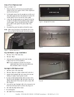
    Pull firmly on the top edge of the Clean Face Front 

until it rotates away from opening of the appliance, 

then lift off of the appliance. See Figure 1.      

2.    To re-install, align the front with the opening around 

the appliance and press firmly onto appliance until 

the front is flush with wall and magnet engage with 

appliance. 

Trim Ring Replacement


1.    Remove the Front.  See Front replacement instruc- 

       tion. 

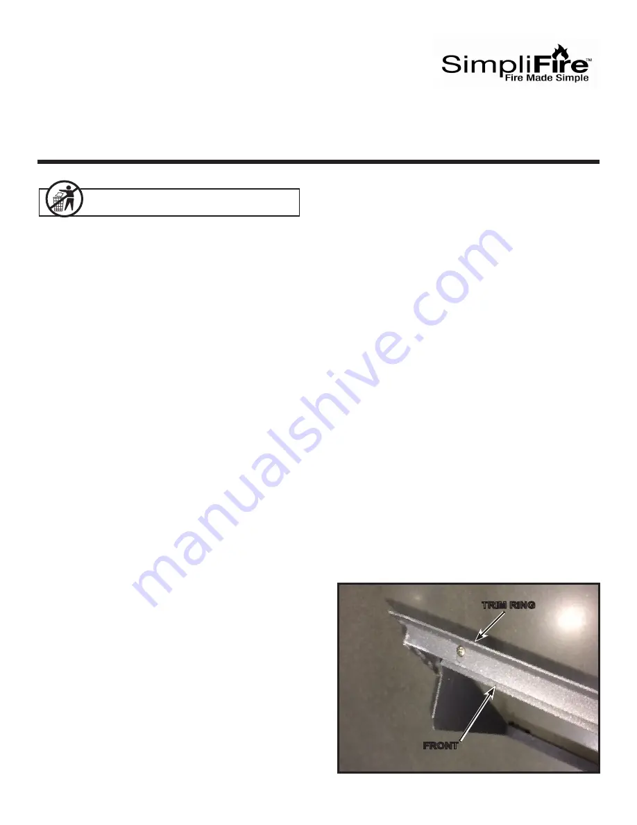
2.    Remove the Trim Ring from the front by remov- 

       ing the screws that attach the two parts.  See Figure  

       1.  Carefully disengage the Trim Ring and remove it 


       from the Front.

3.    With the new Trim Ring set on the floor face down, 


       set the front inside the Trim Ring face down.  Re- 

       install the screws.  See Figure 1.

4.    Re-install the Clean Face Front.


Figure 1.  Trim Ring / Front

TRIM RING

FRONT

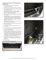
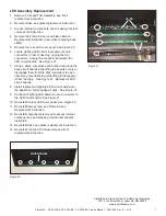
Summary of Contents for SF-SC43-BK

Page 1: ...cket and ratchet for Blower Heater CAUTION Two adults recommended for the removal or installation of glass front Use caution when han dling glass Failure to do so could result in personal injury or property damage WARNING Risk of Personal Injury or Property Dam age Failure to follow instructions below may result in damage to the equipment and or may expose the user to the risk of fire serious inju...

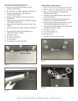
Page 2: ...connector and feed the cable back into the cutout See Figure 5 6 Re install Spotlight LED screws 7 Re install glass 8 Re install Front Trim Assembly Figure 3 Spotlight LED Location Figure 4 Glass Front Replacement Remove Glass Front 1 Remove the two 2 thumb screws and brackets located on the inner upper corners of the appliance opening See Figure 2 2 Tilt the glass away from the appliance and lift...

Page 3: ... wires 9 Re Install 5 screws 10 Re install Spotlight LED 11 Re Install glass 12 Re Install Front and Trim Assembly Figure 6 Figure 7 Control Box Replacement 1 Remove Front see Front replacement instruction 2 Remove Glass see Glass replacement instruction 3 Remove Spot Light LED see Spotlight LED replacement instructions 4 Support the Control Box Assembly and remove 4 screws See figure 8 5 Slowly l...

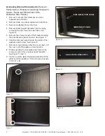
Page 4: ... See Figure 10 5 Remove the screws in each of the brackets holding the Side reflective panels in place See Figure 11 6 Carefully slide each panel toward the center of the appliance and remove See Figure 12 7 Remove screws holding ember bed cover down Lift the cover out of the appliance See Figure12 8 While supporting the rear glass panel remove the screws in each of the rear glass panel brackets S...

Page 5: ...ved to access internal components see Accessing Internal components instruction 10 Re Install glass 11 Re Install Front and Trim Assembly Figure 15 Flame Screen Replacement 1 Remove Front and Trim Assembly see Front replacement instruction 2 Remove Glass see Glass replacement instruction 3 Access internal components see Accessing Internal components instruction 4 Remove the screws in the top Flame...

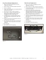
Page 6: ...liace See Figure 18 7 Remove two screws that attach each motor to the motor brackets See Figure 18 8 Remove each motor until the electrical connector is visible See Figure 19 9 Disconnect the electrical connector to the motor See Figure 19 10 Connect the new motors to the electrical connectors 11 Install the replacement motors on the brackets 2 screws each See Figure 17 12 Install the replacement ...

Page 7: ...the boards evenly to disengage them from the clips Use pliers to open clips along rear LED strip while lifting to disengage it from the clips See Figure 21 Remove all LED circuit boards 8 Install replacement lighting LED circuit boards into the appliance Fully engage all clips See Figure 21 9 Connect all lighting LED power source connectors to the LED circuit boards See Figure 21 10 Re install the...

Reviews: