
• The power cable of this product must withstand
a minimum 10A
load.
•
The main supply and interconnecting cables required for installation
of this unit are not included.
•
This unit must be properly grounded.
•
The disconnection of the product is acheived by incorporating a
switch in the fixed wiring in accordance with the wiring rules. The
heater must be isolated from the power by means of a disconnection
switch with a contact separation of at least 3mm.
•
The appliance is not intended for use by persons (including children)
with reduced physical, sensory or mental capabilities, or lack of
experience and knowledge, unless they have been given
supervision or instruction concerning use of the appliance by a
person responsible for their safety.
•
Children should be supervised to ensure that they do not play with
the appliance.
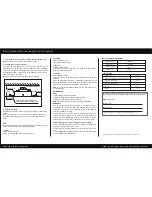
2. Ducting
Put one end of the 100mm diameter ducting into the vent hole and
connect to grille or cowl with one duct clip included. Seal space
around the grille using a suitable sealant. An eggcrate grille is includ-
ed in the package to be used if installed in soffit. If installed in wall a
weather proof cowl should be used (DCT0018).
INSTALLATION
A few minutes of planning can make a big difference to the installation
time and also to your satisfaction with the function of the unit.
1. Cutting a vent
Locate the exterior grille location on a wall or soffit, then cut a 105 mm
diameter hole to install grille/cowl.
Note:
The length of duct is 3.0m. Make sure that from the centre of the
units installated position there must be a distance within 3.0m to the
outside vent.
3. Suitable location
The heater must be installed at least 2.1m above the floor.
The heater is most effective when you are standing directly beneath it,
W all venting shown
wall
sealant
ducting
bathroom
heater
ceiling joist ceiling
fascia
duct clip
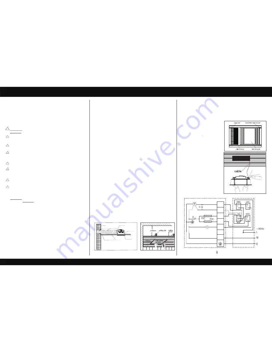
Terminal
Blocks
4. Prepare the ceiling
Use this template to mark the hole
outline on the ceiling. Make sure a
distance between the edges and
wall is no less than 250mm. The
distance from the ceiling board to
the rooftop must be a minimum of
220mm.
5. Remove the fascia
Remove 4 screw covers at 4
corners of the fascia. Remove the
screws hidden behind. Remove
the fascia.
6. Wiring
Open the terminal block cover on
the housing and make connection
as the wiring diagram instructs,
then reposition the terminal block
cover.
INSTALLATION INSTRUCTIONS AND HOLE-CUTTING TEMPLATE
Read and save these instructions!
Please use this card as hole cutting template 420mm×275mm.
EXHAUST
BLOWER
HEATER 1
HEATER 2
LIGHT
L
N
IN
220V-240V
M: Motor C: Capacitor : Thermal protector
IN
: Light lamp
MANROSE
PTC Heater Fan & Light
WARNING
: Indicates that injury or death could occur if below
Warnings
are not followed.
This unit must be installed to comply with the appropriate council
regulations and the Australia and New Zealand wiring rules
AS/NZS3000:2000 or lastest edition thereof.
All wiring must be carried out by a Licensed Electrician in accor-
dance with all applicable codes and standards.
Use this heater only as described in this manual. The manufacturer
does not recommend any other use as this may cause fire, electric
shock, or injury to persons. If you have questions, contact the manu-
facturer or local agent.
Make sure the power is off before the installation.
For the purpose of avoiding any dangerous gas leaking into your
bathroom, the duct vent of the heater must not be laid together with
the duct vent of air-fueled water heater or other open-fire appliances
into the same flue.
The heater is to be installed so that switches and other controls
cannot be touched by a person in the bath or shower.
This unit should not be installed directly above a shower or bathtub.
The unit must not be installed in a position where water may splash
onto the unit.
!
!
!
!
!
!
!
!
Dear customers
Please read all instructions before commencing installation.
CAUTION
: Possibility of damage to equipment, installation or premis-
es if below
Cautions
are not followed.
•
The appliance shall, under no circumstances, be covered with
insulating material or similar material.
•
Regulations concerning the discharge of air have to be fulfilled.
•
The unit must not be installed beneath a fixed socket.
•
The unit is designed for installation in flat ceilings only. Do not mount
it on a sloping ceiling or a vertical wall.
•
Before commencing any cutting, check in the ceiling space that
there are no obstructions such as electrical wiring, hidden utilities
or ceiling joists and that there is sufficient height clearance for the
unit. Check that the electrical wiring can be routed from the wall
switches to the mounting location.
•
Joists, beams and rafters shall not be cut or notched to install the
appliance.
so generally the unit would be mounted in a place where you would stand
to dry yourself. For the exhaust fan to work efficiently, replacement air of a
volume equivalent to what is being extracted must be able to enter the
room. Generally, this air would be drawn under the door with a minimum
space of 20mm. If the room is airtight, the fan extraction will be reduced.


