background image

8 4 0   S I G M A

ENGLISH - ITALIANO

Read  the  instructions  before  use.  This  control  must  be  installed  in  accordance  with  the  rules  in  force

Leggere  le  istruzioni  prima  dell’uso.  Questo  controllo  deve  essere  installato  in  accordo  con  le  normative  in  vigore

9.

95

7.

84

  01

Summary of Contents for 840 SIGMA

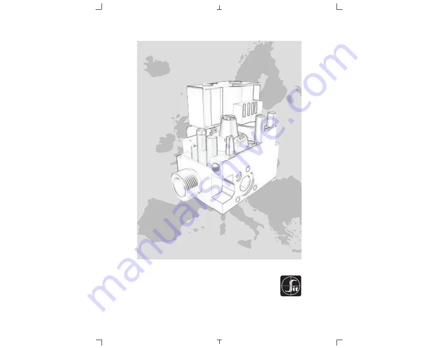
Page 1: ...NO Read the instructions before use This control must be installed in accordance with the rules in force Leggere le istruzioni prima dell uso Questo controllo deve essere installato in accordo con le normative in vigore 9 957 840 01 ...

Page 2: ......

Page 3: ...English GB 14 4 Italiano IT 25 15 ...

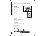
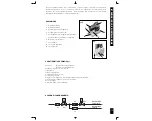
Page 4: ...t point 5 Connection for pressure regulator combustion chamber compensation 6 Pressure regulator 7 Pilot outlet 8 Main gas outlet 9 Side Outlet WORKING DIAGRAM PR EV2 FL EV1 FL MAIN BURNER PILOT BURNER 8 7 9 840 840 2 1 5 4 6 3 MAIN FEATURES ON OFF solenoid valves EV1 Class B on request class A EV2 Class J on request class C Servo pressure regulator PR class B Inlet filter Outlet filter optional P...

Page 5: ...bly position any position Inlet outlet gas connection Male G3 4 B ISO 228 Connections with flanges M4 4 flanges minimum full thread 6 mm Union joint accessory 0 982 001 Female connection Rp 1 2 ISO 7 105 mm version Side oultet M5 3 flanges minimum full thread 7 mm Pilot M10 X1 for 4 mm 6 mm or 1 4 tubing Pressure test point 9 mm Pressure compensation 7 mm AUTOMATIC SHUT OFF VALVES EV1 EV2 EV1 EV2 ...

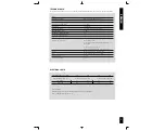
Page 6: ...as Family 6 m3 h 7 m3 h 3 6 m3 h Class B J Flow Q as a function of pressure drop P Third Family Group B P and Group P Inlet pressure range mbar Nominal Max Min Relative Density B P 29 35 25 2 075 P 37 45 25 1 555 Second Family Group H E and L Inlet pressure range mbar Nominal Max Min Relative Density H E 20 25 17 0 555 L 25 30 20 0 612 Minimum flowrate 0 3 m3 h d 0 55 Pu mbar Pu mbar Q m3 h Soleno...

Page 7: ...ific characteristics of the appliance MECHANICAL CONNECTIONS General recommendations SLOW OPENING LEVEL ADJUSTMENT The adjustment is carried out by rotating the adjustment screw This can rotate up to 270 and every position corresponds to a specific ignition level This is also affected by the outlet pressure level The 0 position is obtained by rotating anticlockwise the screw up to the stop positio...

Page 8: ...ble for the use Apply the proper torque to the locking ring according to the washer characteristics in order to ensure the seal WARNING do not over tighten the locking ring Connection with union joint B Use SIT joint 0 982 001 Ensure the locking ring is properly engaged Recommended torque range 40 60 Nm Do not overtorque connection with union joint SIT 0 982 001 locking ring pipe pipe connection w...

Page 9: ...hat the voltage and frequency of the coils given on the valve are correct Disconnect the power supply before starting installation Check that all connections in particular the earth are made properly To make this effective you have to use fast on contact on the body or a female contact of the connector with correct characteristic see EN 60730 When you use connector ensure that the fastening screws...

Page 10: ...lues given in the appliance instruction booklet Changing gas group within the same family Check that the appliance is suitable for operation with the gas group in question Check in the appliance instruction booklet if any operations are necessary when changing the gas group If so adjust the minimum and maximum gas outlet pressures in accordance with the appliance manufacturer s instructions and as...

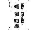
Page 11: ...11 Gas connection G3 4 ISO 228 ENGLISH ...

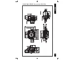
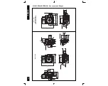
Page 12: ...12 Gas connection Flanges Molex Connector Side Outlet Mounting Holes 80 mm version 105 mm version Optional Rp 1 2 ISO 7 inlet and outlet connection ENGLISH ...

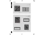
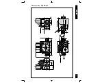
Page 13: ... 33 80 15 12 15 18 3 2 1 55 5 113 75 5 54 5 11 5 27 5 26 12 6 9 6 11 5 18 15 5 5 21 55 8 24 21 13 Molex Connector M5 N 3 HOLES SIDE OUTLET Mounting Holes 13 12 35 26 32 5 22 ø 32 ø 29 ø 26 G 3 4 ISO 228 1 112 65 41 8 3 M4 N 2 HOLES 16 16 2 4 M10x1 6H 28 61 ENGLISH ...

Page 14: ... 24 22 32 5 M4 N 4 HOLES M10x1 6H 75 5 54 5 11 5 27 5 26 18 15 5 5 12 6 9 6 11 5 24 55 8 2 4 Molex Connector M5 N 3 HOLES SIDE OUTLET Mounting Holes 80 mm version 105 mm version Optional Rp 1 2 ISO 7 inlet and outlet connection 112 65 Rp 1 2 ISO 7 75 5 54 5 11 5 27 5 26 18 15 5 5 80 12 15 105 12 5 Molex Connector ENGLISH ...

Page 15: ...olatore di pressione Compensazione camera di combustione 6 Regolatore di pressione 7 Uscita pilota 8 Uscita gas principale 9 Uscita laterale SCHEMA DI FUNZIONAMENTO RP EV2 FL EV1 FL BRUCIATORE PRINCIPALE BRUCIATORE PILOTA 840 2 1 5 4 6 3 CARATTERISTICHE PRINCIPALI Elettrovalvole EV1 Classe B su richiesta Classe A EV2 Classe J su richiesta Classe C Regolatore di pressione tipo servo classe B Filtro...

Page 16: ... Tempo di chiusura elettrovalvola di sicurezza 1 s Posizione di montaggio qualsiasi Connessioni entrata uscita gas Maschio G3 4 B ISO 228 Connessioni con flange M4 4 Profondità minima filettatura 6 mm Giunto di unione accessorio 0 982 001 Connessione Femmina Rp 1 2 ISO 7 versione 105 mm Uscita laterale M5 3 flange profondità minima filettatura 7 mm Pilota M10 x 1 con utilizzo tubi da 4 mm 6 mm o 1...

Page 17: ...3 h 7 m3 h 3 6 m3 h Classe B J Portata Q in funzione della perdita di carico P Terza Famiglia Gruppo B P e Gruppo P Campo di pressione in ingresso mbar Nominale Massima Minima Densità B P 29 35 25 2 075 P 37 45 25 1 555 Seconda Famiglia Gruppo H E e Gruppo L Campo della pressione in ingresso mbar Nominale Massima Minima Densità H E 20 25 17 0 555 L 25 30 20 0 612 Portata minima 0 3 m3 h d 0 55 Pu ...

Page 18: ...ALLAZIONE SIT 840 SIGMA è conforme alle norme di sicurezza vigenti L installazione sugli apparecchi di utilizzazione va comunque verificata a fronte delle norme specifiche relative a ciascuna installazione In particolare deve essere verificato che siano soddisfatti i requisiti relativi al dispositivo di rilevazione fiamma della valvola automatica di intercettazione e del regolatore di pressione Tu...

Page 19: ...n accordo con le caratteristiche della guarnizione per garantire la tenuta ATTENZIONE non eccedere con la coppia di serraggio per evitare di danneggiare la guarnizione Collegamento con tubo sagomato a tenuta metallica B Usare giunto SIT 0 982 001 Assicurarsi che il dado sia inserito correttamente Coppie di serraggio raccomandate 40 60 Nm Non superare la coppia di serraggio raccomandata collegament...

Page 20: ...rmative in vigore Accertarsi che tensione e frequenza delle bobine indicate sulla valvola siano corrette Disattivare l erogazione di corrente prima di inziare l installazione Accertarsi che tutti i collegamenti in particolare quello di massa siano eseguiti a regola d arte Per eseguire questo dovete usare il contatto faston sul corpo o un contatto femmina del connettore con caratteristiche adeguate...

Page 21: ... istruzioni dell apparecchio Cambio del gruppo di gas all interno della stessa famiglia Verificare che l apparecchio sia adatto a funzionare con il gruppo di gas in questione Controllare nel libretto di istruzioni dell apparecchio se ci sono operazioni necessarie quando si cambia il gruppo di gas In caso affermativo regolare la pressione minima e massima dei gas in uscita secondo le indicazioni de...

Page 22: ...22 Collegamento con filetto maschio G3 4 ISO 228 ITALIANO ...

Page 23: ...23 Collegamento con Flange versione 80 mm versione 105 mm Rp 1 2 ISO 7 opzionale collegamento in ingresso ed in uscita ITALIANO ...

Page 24: ...24 USCITA LATERALE Connettore Molex Fori di fissaggio VERSIONE LENTA ACCENSIONE Collegamento con filetto maschio G3 4 ISO 228 ITALIANO ...

Page 25: ...24 22 32 5 M4 N 4 FORI M10x1 6H 75 5 54 5 11 5 27 5 26 18 15 5 5 12 6 9 6 11 5 24 55 8 2 4 Connettore Molex M5 N 3 FORI USCITA LATERALE Fori di Fissaggio Versione 80 mm Versione 105 mm Disponibile anche per collegamento Rp 1 2 ISO 7 112 65 Rp 1 2 ISO 7 75 5 54 5 11 5 27 5 26 18 15 5 5 80 12 15 105 12 5 Connettore Molex ITALIANO ...

Page 26: ...SIT Group www sitgroup it e mail mkt sitgroup it ...

Reviews: