background image

SERVICE MANUAL

8M26

6

 CHASSIS

Description:

MODEL.

Engineering Dept:

Artwork By:

Checked By:

Approved By:

Brand Name:

JOB NO.

Date:

Date:

Date:

SERVICE MANUAL 8M2

6S

2011-

8-10

SKYWORTH

SIZE:A5

Design and specifications are subject to change without prior notice.

(Only Referrence)

Summary of Contents for 8M26S

Page 1: ...scription MODEL Engineering Dept Artwork By Checked By Approved By Brand Name JOB NO Date Date Date SERVICE MANUAL 8M26S 2011 8 10 SKYWORTH SIZE A5 Design and specifications are subject to change without prior notice Only Referrence ...

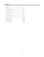
Page 2: ...Content 2 11 17 18 19 20 21 28 29 45 46 49 50 57 ...

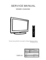
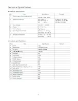
Page 3: ...LED 8M26S ...

Page 4: ...TOSHIBA CODE Component NTSC M PAL M PAL N VHF LOW 2 B VHF HIGH C W 11 VHF W 12 69 55 25MHz 127 25MHz 133 25MHz 311 25MHz 367MHz 801 25MHz ...

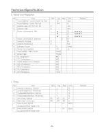
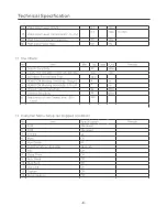
Page 5: ...40 55 80 For 22 LED For 24 LED For 32 LED ...

Page 6: ... 24 inches is 3W 24 inches is 4 ohm ...

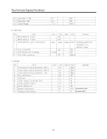
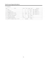
Page 7: ...40 40 3 2 1 4 2 50 0 5 80 40 3 12000 26inches is 8 ohm ...

Page 8: ...40 YES 8 6 46 46 NO NO Standard Spanish Standard 20 ...

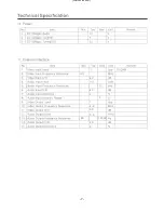
Page 9: ...4 2 4 0 40 70 0 40 70 0 40 40 85 Y0 50 30000 ...

Page 10: ...6E181VS PS331TQFP64G YPbPr AV2 IN HDMI 1 VGA PC EARPHONE AV OUT S PDIP U7 U1 SPEAKER U19 2 P 3 P 1 P TU2 U42 FLASH U29 M13S2561616A 5TG2K ESMT SCL TUNER P7 SDA BH3544F E2 TPA3113D2 AUDIO HDMI 2 P6 P13 P12 CON10 TPA1517NE CON6 MEDIA 1 MEDIA 2 AV1 IN CON11 ...

Page 11: ...3 TERMINAL POSITIVE VOL TAGEREGULATOR LD1117 3 3 SOT 223 8 9 2 523287 1 5 5 5 8 725 72 Thermal Protection For Adjustable Output disconnect A1 and A2 connect B INPUT OUTPUT ADJ GND A1 A2 B For Fixed Output connect A1 and A2 disconnect B 1 2 3 ...

Page 12: ...U28 1A 3 3V SOT 223 AS1117L ADJ U6 1MHZ 800MA SYNCHRONOUS STEP DOWN CONVERTER MP2105DJ TSOT23 5 12 ...

Page 13: ...V A_DDR1_DQ9 A_DDR1_DQ8 UDQS0 UDQM0 AVDD_PLL DVDD_DDR_1 2V LDQM0 LDQS0 AVDDIO_2 5V NC NC A_DDR1_DQ7 A_DDR1_DQ6 A_DDR1_DQ5 AVDDIO_2 5V A_DDR1_DQ4 A_DDR1_DQ3 A_DDR1_DQ2 A_DDR1_DQ1 AVDDIO_2 5V A_DDR1_DQ0 A_DDR1_WEZ A_DDR1_CAS A_DDR1_RAS A_DDR1_BA0 AVDDIO_2 5V A_DDR1_BA1 A_DDR1_A10 A_DDR1_A0 A_DDR1_A1 A_DDR1_A2 A_DDR1_A3 NC NC VDDC GPIO21 PWM1 GPIO20 PWM0 VDDP_2 GPIO77 I2S_OUT_MUTE PWM3 LVSYNC GPIO76 ...

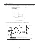
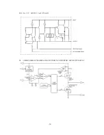
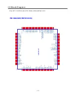
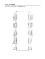
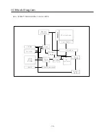
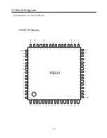
Page 14: ...IC Block Diagram 14 U29 4MX16BIT BANKS DDR M13S2561616A 5TG2K ...

Page 15: ...r ess G ener at or M em or y A rr ay P age B uf fer Y D ecoder D ata R egi st er S R AM B uf fer S I S I O0 S CLK C l ock G ener at or S tate M achi ne M ode Logic S ense A m pl i f i er HV G ener at or O ut put B uf fer S O S I O1 C S W P H O LD ...

Page 16: ...1 Y1 Z2 Y2 Z3 Y3 VCC Z4 Y4 GND I2C_ADDR SCL_CTL SDA_CTL A34 B34 VCC A33 B33 A32 B32 A31 B31 GND SCL3 SDA3 HPD3 POW3 CEXT I2C_RST SDA1 SCL1 B11 A11 B12 A12 B13 A13 B14 A14 REXT POWDN 1 2 3 4 5 6 7 8 9 10 11 12 13 14 15 16 17 18 19 20 50 49 48 47 46 45 44 43 42 41 60 59 58 57 56 55 54 53 52 51 21 22 23 24 25 26 27 28 29 30 31 32 33 34 35 36 37 38 39 40 64 63 62 61 POW_SINK PS331 ...

Page 17: ...2 IC Block Diagram 17 1 2 3 4 5 6 7 8 9 10 28 27 26 25 24 23 22 21 20 19 SD FAULT LINP LINN GAIN0 GAIN1 AVCC AGND GVDD PLIMIT PVCCL PVCCL BSPL OUTPL PGND OUTNL BSNL BSNR OUTNR PGND RINN RINP NC 11 12 13 14 18 17 16 15 OUTPR BSPR PVCCR PVCCR PBTL ...

Page 18: ... 18 ...

Page 19: ... 19 Main PCB Top Bottom Layer ...

Page 20: ...Main PCB Top Bottom Layer 20 ...

Page 21: ...to back to upper menu until leave factory mode Software information Enter factory mode you can get the software information from the bottom of menu Panel information Enter factory mode enter PANEL SETTING item you can get the panel information from the bottom of menu Aging mode Enter factory mode select SYSTEM SETTING item press OK button enter select AGING MODE item press button open aging mode N...

Page 22: ... it will show OK or FAILE If FAILE is showed you need to try again NOTE YPBPR ADC need to do twice by use 576P and 720P signal separate VGA source ADC Switch to PC source input tessellated white and black signal enter factory select AUTO ADC item in the ADC CALIBRATION press button to begin auto adjust When it is finish it will show OK or FAILE If FAILE is showed you need to try again 22 ...

Page 23: ... factory mode enter SYSTEM SETTING item select FAC RESET DEFAULT item and press OK button to reset the flash memory TV set will restart when it is finish Update software by USB Copy the new software name by MERGE bin to the root directory of USB drive Plug the drive to the USB socket if there are two USB socket make sure you use the socket 1 Enter factory select Software Update USB item and press ...

Page 24: ...restart when finish Note you need to restart the TV set again by AC power We suggest you need to do Factory reset after software update 24 ...

Page 25: ...Green offset B OFFSET Blue offset AUTO ADC Auto ADC calibration WHITE BALANCE MODE Select source TEMPERATURE Select Neutral Warm Cool Personal R GAIN Red gain G GAIN Green gain B GAIN Blue gain R OFFSET Red offset G OFFSET Green offset B OFFSET Blue offset COPY ALL Copy there values to all source PANEL SETTING TI MODE LVDS data format LVDS PORT LVDS data interface 25 ...

Page 26: ...HITE PATTERN White test pattern enable POWER REMIND No signal power off time BLUE SCREEN No signal blue screen enable TV source exclusion VIDE AGC Vide AGC DLC DLC enable WHITE BLACK STRENTH White black strength enable POWER CONDITION Power state remember FAC RESET DEFAULT Reset all value to factory default OUT FACTORY SET Reset some value to out box mode AGING MODE Aging mode enable NO SIGNAL MUT...

Page 27: ...NISH FRENCH PORTUGUESE BGI CHINESE SOURCE SETTING TV AV1 AV2 AV3 SCART HDMI1 HDMI2 HDMI3 YPBPR1 USB1 USB2 ANALOG CURVE MODE PICTURE MODE BRIGHTNESS CURVE CONTRAST CURVE SATURATION CURVE HUE CURVE SHARPNESS CURVE 27 ...

Page 28: ... ON VOL VALUE MAX VOLUME POWER ON SOURCE SCALE LOCK CHANNEL SEARCH LOCK OTHER OPTION SSC LVDS and DDR frequency setting UART DEBUG Debug port mode VIF1 VIF setting POWER ON LOGO Logo enable NICAM Nicam enable LOGO SET IN USB Setting logo by use the USB picture USB SRC NAME Change USB name UPLAY USB MEDIA Software Update USB 28 ...

Page 29: ... The graphics are for representation only 2 Power Indicator Remote Sensor 4 Channel Up Down Button 5 Volume Up Down Button 1 3 MENU SOURCE CH VOL 4 5 6 7 8 Front Panel 1 Power Button 3 Speakers 6 Menu Button 7 Source Button 8 Standby Button 2 3 ...

Page 30: ...b Pr Component input Connect YPbPr signal from signal source such as DVD 6 AV1 IN AV2 IN Connect AUDIO and VIDEO input signal from signal source such as DVD 7 AV OUT Connect AUDIO and VIDEO output signal 8 RF IN Connect a coaxial cable to receive signal from the antenna or cable 9 MEDIA1 MEDIA2 MEDIA port 10 EARPHONE Audio output speakers will be muted when earphone plugged HDMI1 HDMI2 PC IN PC AU...

Page 31: ...he cable not provided with this unit then connect to the antenna input of this unit for best reception 2 If the antenna cable in your home is other than the above two or you have problems in installing the antenna please contact your dealer Notes 1 Current outdoor antenna or cable TV usually use 75 OHM coaxial antenna cable For better using this kind of antenna cable reception we suggest 2 Flat ca...

Page 32: ...re aspect ratio 5 6 2 7 8 8 FREEZE Press to freeze or unfreeze the picture 9 10 11 10 Channel Up Down Press to select previous next channel CH 11 Volume Up Down V V Press to adjust the volume 12 12 MTS Option Press to select a different sound mode when the source is different 13 14 13 Menu Press to enter or exit from the TV menu EXTERNAL SCHEMATIC AND INSTALLATION 4 5 SLEEP Press to set the time t...

Page 33: ... previous Media music or movie in mode 23 Next Press to play the next Media music or movie in mode 19 MEDIA Press to the MEDIA menu enter 17 18 18 INFO Press to display relevant information such as screen format source etc 19 20 21 22 23 24 25 25 Stop Press to Media stop the music or movie in mode 15 16 15 OK Press to confirm and execute the selection 16 Up Down Left Right Cursor Press to select o...

Page 34: ...pness of the picture This function is not available in PC mode Brightness Adjusts the brightness of the picture and usually is adjusted together with Contrast Contrast Adjusts the difference between the light and dark areas of the picture To get better picture value Contrast should be adjusted to the proper value Color Adjusts the richness of color This function is not available in PC mode Picture...

Page 35: ... Mode Select the most suitable sound mode according to your watching contents Personal Standard Music Film News Balance Control the audio balance between the right and left TV speakers Surround Press this option to enter to set On or Off AVL This function may be set as On or Off Auto Volume Level can set the volume automatically adjust corresponding to the input audio SOUND Sound Mode Bass Treble ...

Page 36: ...arch Searches and saves channels automatically 1 NTSC MENU Auto Search TV 0 Channel CH 11 56 00 Mhz Air Air Channel Skip b You can skip unnecessary program channels of your choice not to be displayed during viewing and scanning when pressing the buttons Select OFF by pressing uttons to select the channel that would not like to skip from the channel scan operation 53 00MHz Off OSD Language Select y...

Page 37: ...m Password Note Default password is 0000 In the event whereby new password is forgotten it can be reset to default password Please be mindful that all other picture and audio settings will also be reset to default values Block No Rating Press to set the function Block or Unblock the not rating singal TV Rating Press to enter the TV Rating menu Press OK button to set rating block or unblock S L D S...

Page 38: ...ADJUST Press button to auto adjust PC size and position H Position Press button to adjust the H Position of the television V Position Press button to adjust the V Position of the television Phase Press button to adjust the phase of the picture Frequency Press button to adjust the updating frequency of the picture PC Auto Adjust H Position V Position Phase Frequency 50 50 50 50 Note These settings ...

Page 39: ...ich requires electric power source ensure its power does not exceed 500mA 8 An Unsupported File message will be displayed if the file format is unsupported or corrupted Supported Video File Supported Music File Supported Photo File Supported Text Format txt Encoding standard Unicode Media File Playback Support Use cable with the following maximum thickness for optimal connection to this TV or it m...

Page 40: ...ous file 5 Next buttons Press to skip to the next chapter track photo Skip to next file 7 Stop buttons Press the stop button to exit full screen playback access to the preview 1 MEDIA buttons Press to enter MEDIA menu You can play video and music view photo and text files from you USB storage devices 1 Connect USB storage device to MEDIA input terminal 2 Press MEDIA button to enter MEDIA mode 3 Pr...

Page 41: ...sing MEDIA Video Menu Press INFO to display Video Control Bar while playing the video Press to select the desired settings Press to exit from Info bar There are three modes of play mode Press OK button to select Current Track Repeat None and All Tracks Video Control Bar Pause AB Repeat Play 1 Display Mode C Fast Reverse Fast Forward Previous I LIST Current Information Election Play A MEDIA Move Re...

Page 42: ...display lyrics while the music is playing C 1 1 Return MUSIC Super Star mp3 1 Press to select MUSIC Press OK to enter 2 Press to select the desired drive and press OK to enter 3 Press to select the desired folder and press OK to open the folder select the desired music file using OK and press to start playing 4 Press to stop music and return to Music list 5 You may return to Media Player main menu...

Page 43: ...show and return to Photo list 5 You may return to Media Player main menu by pressing MEDIA I Photo Control Bar Press INFO to display Photo Control Bar during photo slide show Press to select the desired settings Press to exit from Info bar Pause Current Information C Resolution 1024 X 768 Size 983 KBytes Date Time 1 1 Return PHOTO Picture01 jpeg Previous Next Stop Zoom In Clockwise 90 Degrees Coun...

Page 44: ... 1 1 Return TEXT Text01 txt 1 Press to select TEXT Press OK to enter 2 Press to select the desired drive and press OK to enter 3 Press to select the desired folder and press OK to open the folder select the desired text file using OK and press to display the text document 4 Press to view previous or next text file 5 Press to select previous or next page in the text file 6 Press to return to Text l...

Page 45: ...ggest to change to the best resolution or other standard resolutions of Windows system Set refresh rate to be 60Hz SNOWY DOTS AND INTERFERENCE If the antenna is located in the fringe area of a television signal where the signal is weak the picture may be marred by dots When the signal is extremely weak it may be necessary to install a special antenna to improve the reception 1 Adjust the position ...

Page 46: ... power supply board Done Done Upgrade the software Check the 5V 12V 24V on power supply board Change the power supply board Check the ON OFF voltage on CON8 should be greater than 2 7V Check Q3 U41 Pin81 if it works well Change the panel Done Upgrade the software Change the Q3 or U9 Change the U41 Done Done Done Done Upgrade the software Done Done Change the EEPROM U43 ATMEL 24C64 Done Done Check ...

Page 47: ...mute Done Check the voltage of Mute pin beside the amplifier IC It should not be 0V Check the mute circuit if it is OK Done Fix the mute circuit Upgrade the software Change the main IC U41 Done Change the mainboard Done Done Check the audio input line the audio input circuit Done Service Flow Chart 47 ...

Page 48: ...ly connected Well connect the cable Check the current input source if it is TV Done Change the main IC U41 Adjust AGC follow the working guide Change the mainboard Done Done Done Check the DC power supply of the tuner Done Fix the DC supply Check the Q29 U25 circuit Check the Q29 U25 circuit Done Change the Q29 U25 Done Done Change the mainboard Change the tuner Done Change the mainboard Done Done...

Page 49: ...s 24V Done Y Y Y N N N Check the ON OFF voltage on CON8 should be greater than 2 7V Check Q3 U41 Pin81 if it works well Change the panel Done Upgrade the software Change the Q3 or U41 Change the U9 Done Done Done Upgrade the software Done Safely connect the LVDS line Make sure the LVDS power is correct 5V for 26 12V for 32 42 Done Change the EEPROM U43 ATMEL 24C64 Done Correct the power Chane the ...

Page 50: ...R14 NC 100K R40 4 7K R40 4 7K R22 NC 0 R22 NC 0 Q44 2SC1815 Q44 2SC1815 R62 100_1 R62 100_1 C114 0 1uF C114 0 1uF C18 10nF C18 10nF L115 220uH L115 220uH R5 NC 0 R5 NC 0 C66 0 1u C66 0 1u C53 1nF C53 1nF C162 0 1u C162 0 1u CA106 100uF16V CA106 100uF16V H2 NC H2 NC 1 2 3 4 5 6 7 8 9 R58 NC 10K R58 NC 10K C121 0 1uF C121 0 1uF Q26 3904 Q26 3904 1 2 3 C390 2 2u C390 2 2u R42 100K R42 100K C47 0 1u C...

Page 51: ...148 R332 4 7K R332 4 7K C487 NC C487 NC C490 NC C490 NC CA109 470uF 16V CA109 470uF 16V C483 NC 330pF C483 NC 330pF C481 1uF C481 1uF R190 10K R190 10K C21 1nF C21 1nF C22 150pF C22 150pF C462 NC 1uF C462 NC 1uF CA114 10uF 16V CA114 10uF 16V R549 0 R549 0 R199 10K R199 10K C479 NC 1nF C479 NC 1nF R326 4 7K R326 4 7K C488 NC C488 NC R544 NC 0 R544 NC 0 C463 NC 1uF C463 NC 1uF U12 TDA1517P U12 TDA15...

Page 52: ...K C110 0 1uF C110 0 1uF C84 47n C84 47n C148 0 1u C148 0 1u R124 200K R124 200K CON38 CON4_2 0 CON38 CON4_2 0 1 2 3 4 C100 0 1u C100 0 1u R122 68R R122 68R R207 4 7K R207 4 7K L120 FB L120 FB R1159 4 7K R1159 4 7K R92 4 7K R92 4 7K L123 FB L123 FB C111 0 1uF C111 0 1uF R171 4 7K R171 4 7K C106 20p C106 20p C80 47n C80 47n C50 47n C50 47n C73 47n C73 47n C125 0 1u C125 0 1u R204 22K R204 22K C135 0...

Page 53: ...73 10R R265 100 R265 100 VD106 NC VD106 NC 1 2 R674 10R R674 10R C88 47n C88 47n R259 37K R259 37K VD107 NC VD107 NC 1 2 R675 10R R675 10R CA85 22uF 16V CA85 22uF 16V R75 10K R75 10K P1 HDMI_J P1 HDMI_J DATA2 1 DATA2 SHIELD 2 DATA2 3 DATA1 4 DATA1 SHIELD 5 DAT1A 6 DATA0 7 DATA0 SHIELD 8 DATA0 9 CLK 10 CLK SHIELD 11 CLK 12 CEC 13 NC 14 SCL 15 SDA 16 DDC CEC GND 17 5V POWER 18 HOT PLUG 19 GND1 20 GN...

Page 54: ...ed y w CON11 RCA3X1 AV 1X3 7 4 5 6 2 3 7 1 R38 5 1R R38 5 1R R224 12K R224 12K R18 4 7K R18 4 7K D141 NC D141 NC 1 2 L22 NC FB L22 NC FB R36 5 1R R36 5 1R C9 0 1uF C9 0 1uF CON6 USB_4P CON6 USB_4P 1 VCC 1 2 D 2 3 D 3 4 GND 4 SHIELD 5 SHIELD 6 R13 0 NC R13 0 NC R19 4 7K R19 4 7K R39 5 1R R39 5 1R R6 100K R6 100K D138 NC D138 NC 1 2 R133 10K R133 10K R37 5 1R R37 5 1R R134 10K R134 10K Q2 3904 Q2 39...

Page 55: ... 2011 Title Size Document Number Rev Date Sheet of VGA V1 0 MST6M181VS OrgName A4 5 10 Monday June 13 2011 C145 0ohm 4 7UF_NC C145 0ohm 4 7UF_NC R285 75R R285 75R R123 100K NC R123 100K NC D137 NC D137 NC 1 2 R396 10K R396 10K R L GND P2 CKX 3 5 32 PHONE_SKY R L GND P2 CKX 3 5 32 PHONE_SKY 2 4 6 7 3 5 1 R112 NC R112 NC D153 NC D153 NC 1 2 D136 NC D136 NC 1 2 P3 VGA P3 VGA 5 10 4 9 3 8 2 7 1 15 14 ...

Page 56: ... 15 17 19 21 24 25 R279 75R R279 75R R127 33R R127 33R R223 12K R223 12K R303 10R R303 10R R141 75R R141 75R R293 47K R293 47K D130 NC D130 NC 1 2 R203 33R R203 33R R215 100R R215 100R R282 75R R282 75R R682 NC 47 R682 NC 47 R692 NC 47K R692 NC 47K D147 NC D147 NC 1 2 R278 33R R278 33R R95 33R R95 33R R165 33R R165 33R R275 33R R275 33R D146 NC D146 NC 1 2 R208 0R R208 0R C817 NC 0 1uF C817 NC 0 1...

Page 57: ...65 0 1u C365 0 1u R291 100R R291 100R C362 0R C362 0R C243 0 1u C243 0 1u R307 68R R307 68R R311 NC 0 R311 NC 0 R362 100K R362 100K R308 0R 560_1 R308 0R 560_1 C369 51R C369 51R C245 0 1uF 50V C245 0 1uF 50V R519 0R R519 0R L116 100uH L116 100uH C241 0 1u C241 0 1u D66 33V D66 33V C242 0 1u C242 0 1u R309 NC 180_1 R309 NC 180_1 L28 0R L28 0R C361 33R C361 33R C360 NC C360 NC C392 2 2u C392 2 2u CA...

Reviews: