background image


S-netx - Single Reader 

T-netx - Dual Reader 

Multi-netx - 8 Readers 


Standard Ethernet or 

Power over Ethernet Interface 

802.3af (48v) 


USER MANUAL


Revision 0 


www.smarteyecorporation.com 


SMARTEYE  

NETWORK READER 

PRODUCTS 

Ethernet IP 


Summary of Contents for Multi-netx

Page 1: ...ngle Reader T netx Dual Reader Multi netx 8 Readers Standard Ethernet or Power over Ethernet Interface 802 3af 48v USER MANUAL Revision 0 www smarteyecorporation com SMARTEYE NETWORK READER PRODUCTS Ethernet IP ...

Page 2: ......

Page 3: ...nsibility for any errors which may appear in this manual Smarteye Corporation SMARTEYE is a registered trademark of Smarteye Corporation BELDEN is a registered trademark of Belden CDT Inc Printed in U S A SMARTEYE contact information SMARTEYE Corporation 2637 Bond Street Rochester Hills MI 48309 Phone 248 853 4495 Fax 248 853 8539 www smarteyecorporation com Email support smarteyecorporation com ...

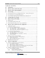
Page 4: ...x Switches SW1 Auxiliary Port Configuration 7 7 2 3 S netx Switches SW2 SW3 SW4 SW5 and SW6 Not Used 8 7 3 T netx Switch and Jumper Diagram 8 7 3 1 T netx Jumper Block J1 Drain Termination 8 7 3 2 T netx Jumper Block 2 9 7 3 3 T netx Switches SW2 SW3 SW4 and SW5 Not Used 9 7 3 4 T netx Power Select 9 7 4 Multi netx Switch and Jumper Diagram 10 7 4 1 Multi netx Jumper Block J1 Port Ground Select 10...

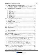
Page 5: ...on webpage 40 11 0 Power Up 41 12 0 Communication 41 12 1 Ethernet IP Control Port Operation 42 12 2 Auxiliary Port Operation 42 13 0 Diagnostic Enable 42 14 0 Error Messages 43 Appendix A S netx SP4002 Drawings A 1 A 1 Sender Receiver Cable Details for Local Mounting Applications SP1054 01 417 A 2 A 2 Sender Receiver Cable Details for Remote Mount Applications SP1054 01 418 A 3 A 3 S netx Install...

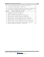
Page 6: ...60 Series Drawings C 1 C 1 Sender Receiver Cable Details SP1054 01 424 C 2 C 2 Multi netx Installation Details SP4060 01 420 C 3 C 3 Multi netx Connection Wiring Details 24VDC SP4060 01 410 C 4 C 4 Multi netx NEMA 12 Installation Details 24VDC SP4061 01 420 C 5 C 5 Multi netx NEMA 12 Connection Wiring Details 24VDC SP4061 01 410 C 6 C 6 Multi netx NEMA 12 Installation Details 110 220VAC SP4061 04 ...

Page 7: ...ting the need for separate power wiring Reader s interface to Smarteye Netx Control Units through the reader port s The reader senses a pattern of coded bars in the Smarteye label As a label passes in front of a reader the coded information is passed along to the Smarteye Netx Control Unit The Smarteye Netx Control Unit then deciphers the coded information and makes the information available to th...

Page 8: ...ons with proper shield termination and equipment grounding are recommended to minimize electromagnetic interference on signal lines Smarteye Netx Control Units should be mounted in such a way to allow complete access to the unit Adequate space must be left to insure that the covers can be opened for maintenance Mounting dimensions for each of the network products enclosures can be found in the app...

Page 9: ...re designed to be powered from 110 to 240 VAC 50 60 Hz These units include an AC circuit breaker and internal 24VDC power supply See the appendix for detailed drawings 5 0 Communication Line Wiring All Smarteye Ethernet IP network products have two communication ports the Ethernet control port and the auxiliary port The S netx is supplied with an RJ45 connector on the inside of the box and a singl...

Page 10: ...the grommet nut can be slipped over the connector for ease of assembly Connection details can be found in the appendix 6 3 Remote Reader Mounting S netx T netx and Multi netx The Smarteye reader can also be remotely mounted from the network control unit S netx T netx or Multi netx A remote field junction box must be located within six cable feet from the receiver assembly This remote junction box ...

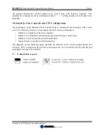
Page 11: ...ye Netx Control Units is contained in the Smarteye CPU circuit card The following features are included in the CPU circuit card hardware Interface to inputs from Smarteye reader s Interface to an Ethernet communication network Ethernet control port Interface to a serial auxiliary port monitor line Jumper blocks to modify shield terminations The diagrams on the following pages describe the function...

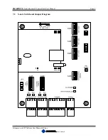
Page 12: ...x Ethernet IP Control Unit User Manual Page 6 Filename netx IP Platform User Manual R0 doc In Control A M 7 2 S netx Switch and Jumper Diagram TX RX J1 SW1 RX TX SW2 SW6 SW5 S NET INTERFACE SW3 SW4 SP4020 01 REV 1 ...

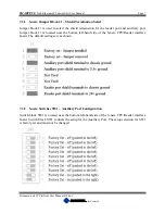
Page 13: ...ader port and auxiliary port Jumper block J1 is located near the bottom left hand side of the S netx CPU Reader interface board The default settings are as shown 7 2 2 S netx Switches SW1 Auxiliary Port Configuration Switch block SW1 is located near the bottom left hand side of the S netx CPU Reader interface board Switch block SW1 controls the setup for the Auxiliary Port The setup selection for ...

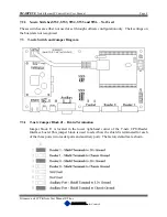
Page 14: ...ugh software configuration only Their settings on the board are not recognized 7 3 T netx Switch and Jumper Diagram 7 3 1 T netx Jumper Block J1 Drain Termination Jumper block J1 is located in the lower right hand corner of the T netx CPU Reader Interface board This jumper block is used to select how the shield is terminated for each of the three ports two reader ports and auxiliary port The facto...

Page 15: ...er installed and the bottom jumper removed These settings should not be altered 7 3 3 T netx Switches SW2 SW3 SW4 and SW5 Not Used Theses switches are either not used or set through software configuration only Their settings on the board are not recognized 7 3 4 T netx Power Select The power select jumper is located on the lower left hand side of the T netx CPU Reader interface board The power sel...

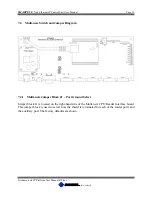
Page 16: ...ti netx Switch and Jumper Diagram 7 4 1 Multi netx Jumper Block J1 Port Ground Select Jumper block J1 is located on the right hand side of the Multi netx CPU Reader Interface board This jumper block is used to select how the shield is terminated for each of the reader ports and the auxiliary port The factory defaults are shown ...

Page 17: ...e top midway between center and the right side of the Multi netx CPU Reader interface board This block is factory set with the top jumper installed and the bottom jumper removed These settings should not be altered 7 4 3 Multi netx Switches SW2 and SW6 Not Used Theses switches are either not used or set through software configuration only Their settings on the board are not recognized ...

Page 18: ...installed for proper shield termination for each of the Netx products 8 0 Software Configuration Before the Smarteye Netx Control Unit can become operational it must first be configured Smarteye Netx Control Units are shipped with a factory default configuration The factory default configuration has the network port enabled All Smarteye Netx Control Units have a auxiliary serial port a network por...

Page 19: ...git hexadecimal numbers separated by dashes An example of a Smarteye Netx Control Unit s MAC address is as follows 00 50 C2 2C 20 00 Configuration through the network port requires the Smarteye Netx Control Unit to be connected to a network through a switch or hub using a standard Ethernet cable RJ45 connectors as shown in the drawing titled Ethernet Port Wiring Details in the appendix The Smartey...

Page 20: ... of this section can be skipped 8 1 2 DHCP Automatic Assignment of IP address If the Smarteye Netx Control Unit is configured to use DHCP and a DHCP server is available on the network the unit will automatically be assigned an IP address If a DHCP server cannot be found then the unit will use the default IP of 192 168 22 243 Normally when requested a DHCP server will assign an arbitrary IP address...

Page 21: ...s The Netx s MAC address along with its assigned IP should be recorded for future reference The unique 12 digit hexadecimal MAC address for the Smarteye Netx Control Unit is displayed on a sticker located on the unit Once the units have been connected to the network the configuration can begin The Smarteye Netx Setup Utility program can be run directly off the provided CD or copied onto and run fr...

Page 22: ... address for this unit into the New IP Address field 3 Enter a valid subnet mask for your network if it is different from the default 4 Enter the default gateway address if required 5 Then click the Set IP Address button to complete the assignment In the example illustrated above a Smarteye Netx Control unit with MAC address 0050C22C21CF is assigned an IP address of 192 168 22 75 with a mask of 25...

Page 23: ...e successfully set IP message box 2 Then click on the description field to connect to the Smarteye Netx unit A red check mark is displayed when a connection is established with the unit Now that a connection has been made we can proceed to the setup page to complete the configuration 3 Click on the Setup tab located near the top left under the Discover tab ...

Page 24: ...configured click the Download button to save the configuration in flash memory The configuration file will be retained even after power is removed from the unit 2 If a timeserver is not present on the network then the date and time can be manually configured by clicking on the Time Time Zone tab located under the parameters tab on the right side See below for an illustration on setting the time an...

Page 25: ...as desired 2 Then click the Download button to update the date and time for the unit 3 The time zone can also be configured from this screen Use the drop down box to select the correct time zone for your area 4 Check the DST box if you want to observe day light savings time 5 Then click the Download button to update the time zone for the unit ...

Page 26: ...how up in the grid each time the search button is clicked 2 The clock button enables the time sync function of the search and discover process When the clock button is in the detent state and the search button is clicked the current date and time of the PC is sent to each Netx Control Unit found on the network When a Netx unit detects this date time data packet in the discovery message it synchron...

Page 27: ... the control unit using a crossover cable or a standard cable with a hub The computers network properties must be altered to match the control unit s default IP address The PC s network card would need to be given a static IP of say 192 168 22 242 for example in order to communicate with the control unit An example of how to do this on a PC running windows 2000 as the operation system is shown bel...

Page 28: ... R0 doc In Control A M Figure 2 Figure 3 Now click the Properties button to bring up the LAN properties window as shown in figure 4 Next select the Internet Protocol TCP IP item and click the Properties button This will bring up the Internet Protocol dialog box shown in figure 5 Figure 4 Figure 5 ...

Page 29: ...illustrated in figure 5 Now we are ready to set the IP address and configure the Smarteye Netx Control Unit Open up a web browser and enter the network address 192 168 22 243 as shown in figure 6 Figure 6 This will cause the Smarteye Netx Control Unit s home page to be displayed as shown in figure 7 Click on the CONFIGURATION link to bring up the control unit s setup page as shown in figure 8 Figu...

Page 30: ...ss assigned to this unit by the network administrator along with the mask and gateway if required 2 If a time server is present on the network then enter its IP address here 3 If no time server is available then the date and time can be manually configured here 4 Select the desired date time and time zone then click the Apply Changes button to set the internal clock of the Smarteye Netx Control Un...

Page 31: ...or a COM port on a computer using a standard 9 pin RS232 serial cable For the auxiliary port interconnection diagram refer to the Auxiliary Port Wiring Details in the appendix The Netx Control Unit does not need to be connected to the network for Auxiliary Port configuration If connected to a computer then a terminal emulator program such as Hyper Terminal will be required The terminal settings sh...

Page 32: ...iary Port Configuration Baud Rate 57600 Parity None Mode OS Console ZiLOG TCP IP Software Suite v2 3 2 Copyright C 2004 2005 ZiLOG Inc All Rights Reserved MAC address 00 50 c2 2c 21 CF IP address 192 168 22 243 No Time Server Specified Set date manually Local time is 04 DEC 2012 14 46 59 Watch Dog Timer Enabled Starting remote discovery process Starting network access port RELEASE version Network ...

Page 33: ...o two groups 1 General Configuration 2 Configure Auxiliary Port For a list and definition of every configuration parameter see the next section The General Configuration group is where the Netx control unit s IP Subnet Mask and Default Gateway parameters are set Once changes have been made use the s command to save the configuration parameters and restart the unit To make configuration changes ent...

Page 34: ...ult Monitoring 1 No 2 Yes 1 Log E99 to History 1 No 2 Yes 1 Keep Alive Interval 0 secs disabled 0 8 2 1 2 Auxiliary Port Configuration Example COMMANDS 1 General Configuration 2 Configure Auxiliary Port d Default Configuration e Erase Flash Configuration s Save and Restart exit Configuration and return to OS shell conf 4 Auxiliary Port Configuration Baud Rate 1 600 2 1200 3 2400 4 4800 5 9600 6 19...

Page 35: ...e default value is 60 minutes Time Zone For Eastern standard time a 5 00 would need to be entered 5 hours from GMT Date Time Set the current date and time in the format shown Watchdog Timer The watchdog timer can be disabled The default value is enabled The WDT monitors the program execution and resets the CPU if a critical fault occurs Password Protect When password protect is enabled users must ...

Page 36: ...rteye Netx Control Unit Configuration Parameters Auxiliary Port Parameter Description Baud Rate Set the baud for the serial Auxiliary port Parity None or Odd parity for the serial Auxiliary port Mode Operating system console or Bluetooth data interface optional 9 0 Monitoring Console show command All Smarteye Netx Control Units has a built in monitoring tool that can be used to 1 Show the current ...

Page 37: ...top bit and no parity 9 1 Show Commands The show mode is programmed to respond to single character commands followed by a carriage return enter key with the exception of the exit command The single character commands are h Help displays a list of valid commands p Photoeyes show the state of the three photoeyes l Label show the last label read d Diagnostic show the last diagnostic values e Error sh...

Page 38: ...ot else a 0 is displayed If photoeye B is blocked a 1 will be displayed in the B slot else a 0 is displayed If photoeye C is blocked a 1 will be displayed in the C slot else a 0 is displayed The following Snetx example shows photo eyes A and B blocked and C unblocked for reader zero show p Rdr 0 ABC 110 A Tnetx unit will show the photo eye state for both readers 0 and 1 a Multi netx will show the ...

Page 39: ... Rdr 0 04 FEB 2008 19 31 54 Diagn A 0 B 0 C 0 X 0 Y 0 Rdr 0 04 FEB 2008 19 31 58 Label 2607 Rdr 0 04 FEB 2008 19 32 04 Diagn A 0 B 0 C 0 X 0 Y 0 Rdr 0 04 FEB 2008 19 32 09 Label 6616 Rdr 0 04 FEB 2008 19 32 09 Error 99 Diagnostic attempt aborted 9 1 7 VERSION v cr The version command displays the current software revision along with the build date The output from the v command looks like this show...

Page 40: ...SMARTEYE Netx Ethernet IP Control Unit User Manual Page 34 Filename netx IP Platform User Manual R0 doc In Control A M SMARTEYE ...

Page 41: ... using a standard web browser Enter the IP address of the unit to be viewed in the address bar of the browser as shown below 10 1 Home webpage The Smarteye Netx Control Unit Home page has general Smarteye Corporation contact information along with links to the other 3 WebPages 1 History page Displays label error diagnostic and alarm messages 2 Ethernet IP page Displays Ethernet IP link information...

Page 42: ...nes 1 General Configuration 2 Auxiliary Port Configuration 3 Time Date and Time Zone configuration The Smarteye Netx Control Unit configuration page has links to the home page history page and Ethernet IP information page There are also three buttons one for restoring the factory default configuration one to apply changes and one for refreshing the page For a description of each setup parameter sh...

Page 43: ... Netx Control Unit is any date between the build date up to the maximum allowable date of 31 JAN 2036 for currently shipping software The software build date can be read from the configuration webpage located directly below the Time Configuration section On power up or when the date time is being manually set if the date value is outside of the valid range the date will be forced to the build date...

Page 44: ...w the read history via the example screen below The History webpage consists of 4 main parts The header at the top has links to the other webpages The display controls located on the left side bubbles 1 4 The display pane bubble 5 located in the middle and the information pane bubble 6 located on the right hand side 1 The Netx history data is composed of 4 message types Labels Errors Diagnostic an...

Page 45: ...the upper or last page will actually vary and will be somewhere between 1 146 to 1 310 pages 5 The display pane shows history messages matching the current filter criteria 1 2 The display pane consists of 4 columns index reader event description and event date time The Index column indicates the position of the message within the history file The indices go from 0 32767 There are 8 4k pages of his...

Page 46: ...nection Although the PLC connects on port 44818 the actual data I O is sent and received on port 2222 2 This field shows the client UDP port used for transferring I O data between the PLC and the Netx Control Unit This is a fixed port number and is always 2222 3 This field shows the client data size in words The size is a fixed length of 46 words 4 This field shows the current mode of the PLC The ...

Page 47: ...controller generates a power up error for each reader Therefore a zero in this field means there have been no other errors since the last reboot other than the initial power up error 12 The Refresh Page button updates the page with the most current data 11 0 Power Up After the Smarteye Netx Control Unit has been mounted and the DC power is terminated an initial checkout can be completed When power...

Page 48: ...for the auxiliary port is user selectable The factory default settings for the auxiliary port are RS232 57600 baud 8 bits 1 stop bit and no parity For the auxiliary port interconnection diagram refer to the Auxiliary Port Wiring Details in the Appendix If the Bluetooth interface option is purchased the auxiliary port is configured for Bluetooth data mode 13 0 Diagnostic Enable A diagnostic message...

Page 49: ...gnizable label incorrect number of data bits LSD least significant digit of error is the LSD of the number of data bits in the label read Errors 91 through 99 are detected during diagnostic 91 Photoeye A insufficient number of transitions in time allowed 92 Photoeye B insufficient number of transitions in time allowed 93 Photoeyes A and B insufficient number of transitions in time allowed 94 Photo...

Page 50: ...n Details No Power over Ethernet SP4002 01 420 This drawing shows the mounting dimensions of the S netx S netx Connection Wiring Details No Power over Ethernet SP4002 01 410 This drawing shows the location and wiring details for the Ethernet and power connections S netx Installation Details Power over Ethernet SP4002 02 420 This drawing shows the mounting dimensions of the S netx S netx Connection...

Page 51: ......

Page 52: ......

Page 53: ......

Page 54: ......

Page 55: ......

Page 56: ......

Page 57: ......

Page 58: ...ls for the Ethernet and power connections for T netx models SP4050 01 and SP4051 01 T netx Connection Wiring Details Power over Ethernet SP4050 02 410 This drawing shows the location and wiring details for the Ethernet connection for T netx models SP4050 02 01 and SP4051 02 T netx NEMA 12 Installation Details SP4051 01 420 This drawing shows the mounting dimensions of the T netx T netx NEMA 12 Con...

Page 59: ......

Page 60: ......

Page 61: ......

Page 62: ......

Page 63: ......

Page 64: ......

Page 65: ......

Page 66: ... This drawing shows the mounting dimensions of the Multi netx Multi netx NEMA 12 Connection Wiring Details 24VDC SP4061 01 410 This drawing shows the location and wiring details for the Ethernet and power connections Multi netx NEMA 12 Installation Details 110 220VAC SP4061 04 420 This drawing shows the mounting dimensions of the Multi netx Multi netx NEMA 12 Connection Wiring Details 110 220VAC S...

Page 67: ......

Page 68: ......

Page 69: ......

Page 70: ......

Page 71: ......

Page 72: ......

Page 73: ......

Page 74: ......

Page 75: ......

Page 76: ...www smarteyecorporation com ...

Reviews: