background image

Assembly instructions

Power supply

Always use a UL or CE marked wall power supply with the included splitter cables. Use a wall power 

supply that can deliver enough current for your application. For best results, use a 5.1 volt power 

supply to avoid low voltage warning on the display. The official Raspberry Pi power supply is recom-

mended. 

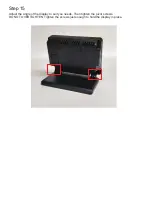
The splitter cables are only for use with the Raspberry Pi and Official Raspberry Pi display. 
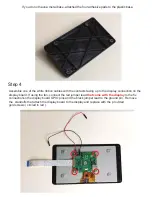
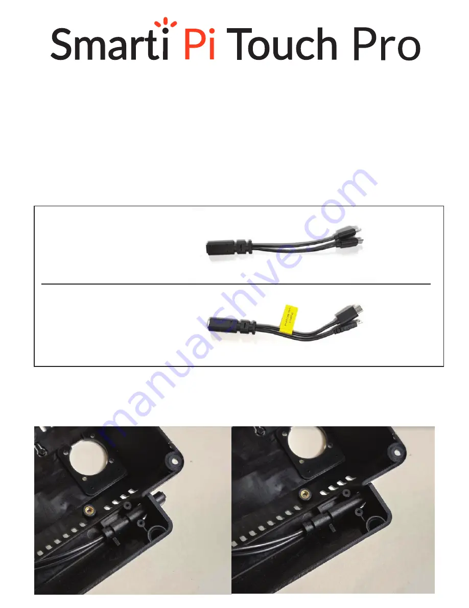
Step 1

Please choose which splitter works your Raspberry Pi model. Insert the female end into the back cover

as shown below. The cable can be assembled in either of two positions. Option 1 extends further out for 

easier access. Option 2 is the more compact option.   

option 1

option 2

Questions or missing parts? Email    info@smarticase.com

5.1 V 2.5A Micro USB Power

supply recommended

5.1 V 3A USB-C  Power

supply recommended

Raspberry Pi 2 and 3

Raspberry Pi 4

Micro USB input

USB-C input

USB-C (Pi 4)

Micro USB (display)

Micro USB (display)

Micro USB (Pi 2 and 3)

Drawings and CAD files are available at smarticase.com

Summary of Contents for Pi Touch Pro

Page 1: ...y Pi display Step 1 Please choose which splitter works your Raspberry Pi model Insert the female end into the back cover as shown below The cable can be assembled in either of two positions Option 1 e...

Page 2: ...metal base on the bottom of the plastic base The metal base can only properly assemble onto the base one way Please make sure all of the holes are aligned Use the four silver screws to attach the meta...

Page 3: ...he red jumper lead that came with the display to the 5v connectionon the display board GPIO pins and the black jumper lead to the ground pin Remove the standoffs that attach the display board to the d...

Page 4: ...p 5 Attach the display to the housing using the green screws as shown below Feed the white ribbon cable through the slot in the center of the housing Feed the fan power leads through the hole at the t...

Page 5: ...nd one for Pi 4 Step 7 Assemble the port block part and the Raspberry Pi at the same time to the display housing Use the standoffs that were removed in step 4 to hold the Raspberry pi in place You can...

Page 6: ...the camera If you choose to use the camera the Official Raspberry Pi camera can be assemble into the these holes with two of the small black screws You can choose to mount the Raspberry Pi in the oth...

Page 7: ...with the large black screws and nuts DO NOT OVERTIGHTEN Loosely attach the screws at this point Step 10 If you choose to not use the fan the small door can be assembled into the hole in the back cove...

Page 8: ...w Push the small end of the mount through the back cover from the outside Then pull it through the cover as shown Then pull the rubbers mounts through the fan holes and pull the thin end of the mount...

Page 9: ...ower leads from the display to the red and black on the fan Assemble the back cover to the display housing with the four black screws The port blocking part should have tabs that fit inside the housin...

Page 10: ...Step 15 Adjust the angle of the display to suit you needs Then tighten the pivot screws DO NOT OVERTIGHTEN Tighten the screws just enough to hold the display in place...

Page 11: ...m apart If the case came with a blank adhesive panel for the front this can be used to permanently hide the camera hole Align the label with the small edge in the plastic below the display Do not have...

Reviews: