background image


USER MANUAL 


3.1 

05-11-2015 

D. Cavalli 

REV. 

DATE 

R.T. Check and Approval 


http://www.sms.bo.it 

T

T

a

a

k

k

e

e

d

d

o

o

®

®


E

E

n

n

e

e

r

r

g

g

y

y


Summary of Contents for TAKEDO ENERGY

Page 1: ...USER MANUAL 3 1 05 11 2015 D Cavalli REV DATE R T Check and Approval http www sms bo it T Ta ak ke ed do o E En ne er rg gy y ...

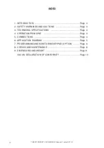
Page 2: ...ARNINGS AND CAUTIONS Page 3 3 TECHNICHAL SPECIFICATIONS Page 3 4 OPERATION PRINCIPLE Page 3 5 CONNECTIONS Page 4 6 APPLICATION DIAGRAM Page 5 7 PROGRAMMING AND MONITORING KEYPAD OPTION Page 6 8 CHECKS AND MAINTENANCE Page 8 9 DIMENSIONS AND WEIGHT Page 9 VACON DECLARATION OF CONFORMITY Page 10 ...

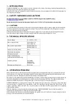
Page 3: ... 16 Stand By consumption 3W Working duty cycle 100 FAULT OPTION relay with NXOPTA2 Board only Switching Power Minimum switching load 24Vdc 8A 250Vac 8A 125Vdc 0 4A 5V 10mA 4 OPERATION PRINCIPLE When the lift motor is pulled by the load for example running upward with empty car or downward with full load in the car or in any case of favorable weight all the energy of the excess weight that descends...

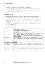
Page 4: ... to the motor and from the cable that connects the braking resistor to the main inverter 50 cm at least 5 3 POWER CONNECTIONS MAINS wiring The mains must be connected to terminals L1 L2 L3 of TAKEDO ENERGY following the drawing shown at Chapter 6 It is not necessary to respect the phase sequence BUS wiring The terminals B and B must be connected to the BUS of the main inverter Should NOT be connec...

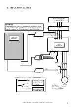
Page 5: ...22 21 23 FAULT relay powered when TAKEDO ENERGY is ready to run Contact to inform the controller of the TAKEDO ENERGY failure NOTE 1 NOTE 1 The braking resistor has not to be eliminated OPTIONAL contact available with NXOPTA2 Board only FILTER IMPORTANT If the existing motor inverter is provided with an INSIDE FILTER you must install an external added filter so that the connection of TAKEDO ENERGY...

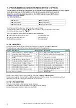
Page 6: ...for the application Indice Descrizione Unità Indice Descrizione Unità V1 1 Tensione bus C C DC link Voltage V V1 11 R01 Fault R02 Contactor V1 2 Corrente Totale Total Current A V1 13 Rif Ingr Analogico Analogic input V1 3 Potenza Rigenerata Regenerated Power kW V1 14 Inseguitore Follower V1 4 Corrente Attiva Active Current V1 15 Corrente fase U U Phase Current A V1 5 Corrente Reattiva Reactive Cur...

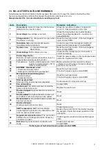
Page 7: ...16 Temperature inverter undertemperature 10 C inverter overtemperature 90 C motor overtemperature Make certain the air flow around the drive is sufficient to cool the heat sink and or check for possible motor overload 22 23 EEPROM Checksum error Parameter recovery failed Damaged or malfunctioning component Reset the fault and restart If the fault happens again contact SMS 25 Microprocessor watch d...

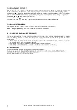
Page 8: ... 11 submenus S6 1 Language Setting ITALIAN ENGLISH FRENCH GERMAN 8 CHECKS AND MAINTEINANCE To ensure long service life and smooth operation of the drive carry out the following checks at regular intervals Always isolate the drive from the power supply and make certain the keypad is off before proceeding 1 Remove the dust that collects on the cooling fans and on the control circuit board preferably...

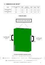
Page 9: ...IGHT SIZES Max Rigenerated Power kW Width mm Width with handles mm Height mm Depth mm Weight kg TAKEDO ENERGY 4 3 3 00 394 480 520 180 22 5 TAKEDO ENERGY 12 8 00 394 480 520 180 35 FIXING DRAWING For further information and advice contact Fix box top with n 2 hook rawl plugs Fix handle to plate with n 2 M6 hex screws ...

Page 10: ... 3 1 dated 05 11 15 10 Fix handle to plate with n 2 M6 hex screws Fix handle to plate with n 2 M6 hex screws FIXING DRAWING Fix box top with n 2 hook rawl plugs Fix plate to base with n 3 M5 screws Fix plate to base with n 3 M5 screws ...

Reviews: