background image


DESCRIPTION 

Structure in aluminium Ø80 

Powder coated 

3.0 x 2.0 m 


CONFORM 


ASSEMBLY INSTRUCTION 

ALUMINIUM FOLDING GOAL, MOBILE 

PRODUCT REF

S16118


PAIR


ASSEMBLY TIME 

The assembly time for this goal is estimated between 30 to 45 minutes at 2 persons (without concreting). 

TEST AFTER INSTALLATION 

According to the regulation above, this product has to be tested as below: 


- Put 180kg at 20cm from the ground and in the middle of the crossbar for 1min. 

- Apply an horizontal force of 110 kg on the middle of the crossbar, by a 3 meter rope, for 1min.  

After these tests, the equipment and the fixation system should not have a break, move or show residual                            

deformation. 


During the first installation, stability and strength tests are compulsory.  

Every time you install the equipment, a visual check of the stability and strength must be realized.  

The owner of this equipment must usually control the product. 


For an optimal use of our products, we advise to follow the installation and maintenance instructions. 

MAINTENANCE 

The equipment has to be regularly maintained by the owner. It is recommended to: 

- Check every week that all the bolts are correctly tightened. 

- Fix paint defects if the unit has been damaged, using the adapted paint specified by the manufacturer. 

- Replace all damaged or missing parts with a spare part recommended by the manufacturer.  

- Clean the product by using dishwasher soap, clean water, and soft cloth. 

WARRANTY


One full year parts and labour guarantee. Every claim regarding the condition of the delivered equipment has to be 

done within the warranty period following receipt of the product. 

The warranty will not apply to: 

    -    Any degradation during transport. 

    -    Any degradation due to poor maintenance. 

    -    Any degradation due to use differing from which the product was intended. 

    -    Any defect claimed after the end of the warranty period. 

    -    Any damage due to a faulty installation or assembly of the product. 

Summary of Contents for S16118

Page 1: ...quipment must usually control the product For an optimal use of our products we advise to follow the installation and maintenance instructions MAINTENANCE The equipment has to be regularly maintained by the owner It is recommended to Check every week that all the bolts are correctly tightened Fix paint defects if the unit has been damaged using the adapted paint specified by the manufacturer Repla...

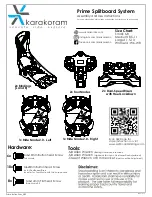
Page 2: ...EMBLY FOR LEFT POST CROSS BAR RIGHT POST SS screws M10x30 SS Washers 10 x4 Turn knobs M10x50 Step 01 Step 02 Mallet Wrench 17mm Wrench 13mm x24 SS Washers 8 SS Screws M8x20 x24 x12 SS Locknut M10 x32 SS Washers 10 x4 SS Screws M10x100 x4 Part thread SS screws M10x55 x4 Part thread SS screws M10x65 x8 SS Screws M10x30 x2 SS Washers 10 x2 SS Screws M10x30 ...

Page 3: ... 8 SIDE GROUND BAR REAR GROUND BAR SS Screws M8x20 SS Washers 8 Note The hooks on the upper frame have to be on the inside of the goal while the hooks on the ground frame have to be on the outside of the goal Upper frame Ground frame x2 SS Washers 8 SS Screws M8x20 x2 SS Screws M8x20 SS Washers 8 x4 SS Washers 8 SS Screws M8x20 x4 ...

Page 4: ... SS Washers 10 Nylon washers Note the nylons washers have to be inserted into the U also for step 5 x2 Nylon Washers M10 x2 SS Locknut M10 x2 SS Washers 10 x1 SS Screws M10x100 x4 Nylon Washers M10 x1 Part thread SS screws M10x55 x1 Part thread SS screws M10x65 x4 SS Washers 10 x1 SS Locknut M10 Note Putting the nylon washers in position during the insertion of the screws may no be easy We recom m...

Page 5: ...nterweight Note Put the counterweights on the rear bars paying attention to these details The slot done under the counterweight is done to receive the rear bar The lower side of the counterweight has to be put into the goal in order to lead the ball into the net when it hits it Place the counterweights regularly along the rear bar in order to make the goal as stable as possible ...

Page 6: ...ight ground frame left right Vertical bar 1 1 1 1 2 S16112 06 A Side ground bar left right 1 1 A4 S16112 02 B Left post Right post 1 1 Plastic bubble Carton 5 layers 23 5 2300x420x250 S16112 03 B Upper frame left right ground frame left right Vertical bar 1 1 1 1 2 S16112 06 A Side ground bar left right 1 1 A5 S16118 08 A Rubber counterweight 1 Plastic bubble Carton 2 layers 29 720x320x150 A6 1 29...

Page 7: ...M10x30 SS Washers 10 8 8 To fix the cross bar to post A11 LNA102020 Nylon washers 10 24 Inserted in the con nections A11 BITH0820 LITA081815 SS screws M8x20 SS washers 8 24 24 To fix the ground bar A11 BITI1065 LITA102220 TITD10 Part thread SS screws M10x65 SS washers 10 SS locknut M10 4 8 4 To fix the rear bar A11 BITI1055 LITA102220 TITD10 Part thread SS screws M10x55 SS washers 10 SS locknut M1...

Reviews: