
1
Introduction
Thank you for purchasing Sonance Visual Performance
®
Single-
Stereo Technology
®
(SST) and surround (SUR) speakers. When
properly installed your new speakers will give you years of enter-
tainment pleasure. This manual covers the following speaker
models: VP65R SST; VP65R SUR, VP65S SST, VP65S SUR, VP65 SST.
Box Contents
IItteem
m
Q
Quua
annttiittyy ((S
SS
STT))
Q
Quua
annttiittyy ((S
SU
UR
R))
Visual Performance Speaker
1
2
Paintable Grille
1
2
Plastic Paint Plug
1
2
Mounting Cutout Template
1
1
Speaker Placement
SST Models
Because a single SST speaker reproduces both stereo channels
from a single location, it will deliver outstanding performance
from a wide variety of mounting locations where a pair of stereo
speakers would be impractical, including hallways, bathrooms
and closets.
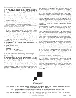
The table below shows how far apart SST speakers can be
spaced in distributed audio applications while still providing
good coverage for standing and seated listeners (see
Figure 1
).
C
C ee ii ll ii nn g
g H
H ee ii g
g hh tt
S
Sp
pa
acciinng
g ((S
Stta
annd
diinng
g))
S
Sp
pa
acciinng
g ((S
Seea
atteed
d))
9-Foot Ceiling
5’7”
9’5”
10-Foot Ceiling
9’7”
13’5”
12-Foot Ceiling
13’7”
17’5”
14-Foot Ceiling
17.7’
21.5’
SUR Models: 5.1-Channel Home Theater System
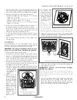
Mount the left and right surround speakers on the ceiling
between 2 feet and 6 feet behind the listening position.
The speakers should be between 6 feet and 10 feet apart. Orient
the speakers so the tweeters face the front and rear walls of the
room. Use
Figure 2
as a guide.
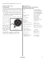
SUR Models: 7.1-Channel Home Theater System
Mount the left and right surround speakers directly to the sides of
the listening position, between 6 feet and 10 feet apart. Mount
the surround back speakers between 2 feet and 6 feet behind the
listening position. The surround back speakers should be closer
together than the left and right surround speakers — between
3 feet and 6 feet apart. Use
Figure 3
as a guide.
Before Installation: Retrofit
1. Determine the location for the speaker (see
Speaker Placement
above).
S
A F E T Y
W
A R N I N G
:
T
HESE SPEAKERS HAVE
F
AST
M
OUNT
®
TABS THAT PREVENT THE
SPEAKERS
FROM
FALLING
OUT
OF
THE
MOUNTING
HOLES
DURING THE INSTALLATION PROCESS
.
THE EDGES OF THE FASTMOUNT TABS ARE VERY
SHARP.
U
SE CAUTION WHEN HANDLING THE SPEAKERS
.
C
OVERAGE
A
REA
C
OVERAGE
A
REA
S
PEAKER
S
PACING
F
IGURE
1: D
ISTRIBUTED
A
UDIO
C
OVERAGE
A
REA
TV
3' – 6'
apa
r
t
2' – 6'
Su
rr
ou
n
d
Back
Speake
r
Su
rr
ou
n
d
Back
Speake
r
Right Su
rr
ou
n
d
Speake
r
Le
f
t Su
rr
ou
n
d
Speake
r
F
IGURE
3: SUR S
PEAKER
P
LACEMENT IN A
7.1-C
HANNEL
S
YSTEM
I N S T R U C T I O N M A N U A L
V I S U A L P E R F O R M A N C E
®
S E R I E S
6 ” S S T A N D S U R S P E A K E R S
TV
6' – 10'
apa
r
t
2' – 6'
Right Su
rr
ou
n
d
Speake
r
Le
f
t Su
rr
ou
n
d
Speake
r
F
IGURE
2: SUR S
PEAKER
P
LACEMENT IN A
5.1-C
HANNEL
S
YSTEM


