


Summary of Contents for KCS-3500
Page 1: ...Model KCS 3500 Color Scanning Sonar Operation Manual Ver 1 6...
Page 2: ......
Page 16: ......
Page 26: ......
Page 62: ......
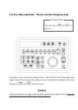
Page 70: ...7 8...
Page 85: ......
Page 86: ......
Page 87: ......
Page 88: ......
Page 89: ......
Page 90: ......
Page 91: ......
Page 92: ......
Page 93: ......
Page 94: ......
Page 95: ......
Page 96: ......
Page 97: ......
Page 98: ......
Page 99: ......
Page 100: ......
Page 101: ......
Page 102: ......


