background image

SERVICE MANUAL

LCD Digital Color TV

AZ2-F 

Chassis

Segment: 3a-1

9-888-410-01

Version  Date 

Subject

1.0  

3/1/2011 

No revisions or updates are applicable at this time. 

ORIGINAL MANUAL ISSUE DATE: 2/2011

HISTORY INFORMATION FOR THE FOLLOWING MANUAL:

Summary of Contents for BRAVIA KDL-40NX725

Page 1: ...Digital Color TV AZ2 F Chassis Segment 3a 1 9 888 410 01 Version Date Subject 1 0 3 1 2011 No revisions or updates are applicable at this time ORIGINAL MANUAL ISSUE DATE 2 2011 HISTORY INFORMATION FOR THE FOLLOWING MANUAL ...

Page 2: ...SERVICE MANUAL LCD Digital Color TV AZ2 F Chassis Segment 3a 1 9 888 410 01 SelfDiagnosis Supported model KDL 46NX725 ...

Page 3: ...DEL LIST MODEL COMMANDER DESTINATION MODEL COMMANDER DESTINATION KDL 40NX725 RM YD062 CHILE PERU KDL 40NX725 RM YD062 VENEZUELA KDL 46NX725 RM YD062 CHILE PERU KDL 46NX725 RM YD062 VENEZUELA 9 888 410 01 ...

Page 4: ...art Up 10 Energy Saving Switch 10 USB Photos Videos Music 10 LightSensor Technology 11 BRAVIA Sync Compatible 11 Specifications 12 Section 2 Software Requirements 15 Overview 15 Software Updates for Customers 15 Software Updates for Servicers 16 Software Update Responsibility 16 Checking the Software Version 16 Examples of Software Correctable Symptoms 17 Section 3 Chassis Overview 18 Overview 18 ...

Page 5: ... Removal 44 G4BW G5AW Power Supply Board and LD Board Removal 45 BATL Main Board Removal 46 Center Cabinet HLT2 Board and LCD Panel Removal 47 Cleaning the LCD Panel 47 Screws 48 Connectors 48 KDL 40NX725 Only 48 KDL 46NX725 Only 48 Accessories and Packaging 49 Miscellaneous 49 Remote Commander 49 Wire Dressing 50 KDL 40NX725 Only 50 KDL 46NX725 Only 50 Section 7 Service Adjustments 51 Overview 51...

Page 6: ...40NX725 46NX725 iii TABLE OF CONTENTS Appendix A Removing the Rear Cover A 1 Removing the Power Cord from the Rear Cover A 1 Appendix B Attaching the Rear Cover B 1 KDL 40NX725 Only B 1 KDL 46NX725 Only B 2 ...

Page 7: ...is The chassis of this receiver is directly connected to the AC power line SAFETY RELATED COMPONENT WARNING Components identified by shading and mark on the exploded views are critical for safe operation Replace all components with Sony parts whose part numbers appear as shown in this manual or in supplements published by Sony It is essential that all critical parts be replaced only with the part ...

Page 8: ...ter or detergent directly onto the TV screen If liquid drips into the bottom of the screen it may cause a failure CLEANING THE LCD PANEL CAUTION When cleaning the TV be sure to unplug the power cord to avoid any chance of electric shock Clean the cabinet of the TV with a dry soft cloth Wipe the LCD screen gently with a soft cloth R Stubborn stains may be removed with a cloth slightly moistened wit...

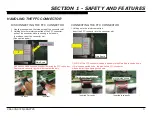
Page 9: ...t tab of the FFC connector pull out the connector while continuing to hold down the release tab of the connector slot See caution below Use the tab to insert connector 2 Press down Main Board Main Board CAUTION The FFC connector can be inserted into the Main Board upside down If it is inserted upside down the pins on the FFC connector will short circuit and damage the board Reinforcement tab shows...

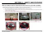
Page 10: ... removing the boards and connectors note where the frame is on the panel Figure 1 2 Lift the LCD Panel Assembly by holding the top and bottom of the panel approximately 200mm from the edge with your palms on the back of the panel Figure 2 CAUTION Lifting or holding the panel at the corners may damage the panel 3 Use the same method when taking the replacement panel out of the carton Figure 3 Figur...

Page 11: ...high temperatures or in areas of high humidity for an extended period of time 4 Do not expose the LCD panel to direct sunlight 5 Avoid contact with water It may cause a short circuit within the module 6 Disconnect the AC power when replacing the backlight or inverter circuit High voltage occurs at the inverter circuit at 650Vrms 7 Always clean the LCD panel with a soft cloth material 8 Use care wh...

Page 12: ...d straps and mounting hardware have been replaced Be absolutely certain that you have replaced all the insulators 4 Look for unauthorized replacement parts particularly transistors that were installed during a previous repair Point them out to the customer and recommend their replacement 5 Look for parts which though functioning show obvious signs of deterioration Point them out to the customer an...

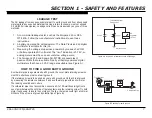
Page 13: ... VOMs that are suitable Nearly all battery operated digital multimeters that have a 2 VAC range are suitable see Figure A HOW TO FIND A GOOD EARTH GROUND A cold water pipe is a guaranteed earth ground the cover plate retaining screw on most AC outlet boxes is also at earth ground If the retaining screw is to be used as your earth ground verify that it is at ground by measuring the resistance betwe...

Page 14: ...tes to a probable source of the problem A definition of the standby LED flash indicator is listed in the Operating Instruction manual for the user s reference If an error symptom cannot be reproduced the remote commander can be used to review the failure occurrence data stored in memory to reveal past problems and how often these problems occur For complete information refer to Section 4 Troublesh...

Page 15: ...contrast with local dimming technology It sharpens image contrast giving an amazingly crisp picture you can see The backlight system allows for a more environmentally friendly television than traditional CCFL tube TVs SLEEK DESIGN Sony s monolithic design consists of an elegant sheet of glass stretching from edge to edge It looks just as good when it s off as it does when it s on OPTICONTRAST PANE...

Page 16: ... Enjoy a vivid lifelike picture experience Sony s X Reality engine brings out the best by analyzing each scene so you see sharpened images and amazing contrast detail INTELLIGENT PRESENCE SENSOR Enjoy an incredibly customized picture and sound experience every time Sony s Intelligent Presence Sensor uses built in Face Detection technology to turn itself off if no one is watching warns children whe...

Page 17: ...Light Sensor automatically adjusts the picture brightness based on the amount of light in the room BRAVIA SYNC COMPATIBLE Conveniently operate and control other BRAVIA Sync compatible devices including BRAVIA HDTVs Blu ray Disc Players surround sound systems Handycam camcorders and Cyber shot digital still cameras all with one remote control when connected via HDMI ...

Page 18: ...80p 576i 576p 720p 720 24p 30p 1080i 1080p 1080 24p 30p HDMI Audio PCM lineal de dos canales 32 44 1 y 48 kHz 16 20 y 24 bits Dolby Digital Entrada de audio analógico minitoma solo HDMI IN 4 ARC solo HDMI IN 1 AUDIO OUT Salida de audio Auriculares 500 mV rms típico Minitoma estéreo DIGITAL AUDIO OUT OPTICAL Señal de audio óptica digital PCM Dolby Digital PC IN Entrada de PC Subminiatura D de 15 co...

Page 19: ...2 9 1 r o t i n o m l e d n ó i c u l o s e R Bocina Gama completa mm De bajas frecuencias mm 20 90 2 60 1 3 1 2 8 1 6 9 4 9 8 5 2 4 9 6 4 8 0 1 m m e t r o p o s n o c s e n o i s n e m i D 7 2 7 8 5 9 4 9 7 2 3 6 6 4 8 0 1 m m e t r o p o s n i s patrón de orificios de montaje mural mm 300 300 tamaño de tornillos de montaje mural mm M6 longitud consulte el Guía de configuración 0 7 1 2 0 2 g k e...

Page 20: ...ETECTION es una marca comercial registrada de Sony Corporation TrackID es una marca comercial o una marca comercial registrada de Sony Ericsson Mobile Communications AB La tecnología de reconocimiento de música y video y la información relacionada es proporcionada por Gracenote Gracenote es el estándar de la industria para la tecnología de reconocimiento de música y para la distribución del conten...

Page 21: ...ome Some examples are Portable audio and video devices still cameras home computer networks and accessing the internet to name a few Communications with these varying devices requires that the television be compatible with varying communications protocols Although standards are detailed for each of these protocols the real world dictates that occasional errors may occur that could prevent devices ...

Page 22: ...dition to software installation service adjustment information may need to be modified or verified to complete the service of the TV Service adjustment information is covered in Section 7 Service Adjustments on page 51 SOFTWARE UPDATE RESPONSIBILITY Software updates are designed to be performed by the customer Warranty repairs in which the issue can be resolved by a software update are not reimbur...

Page 23: ... of the symptoms that may be corrected with a software update Fluctuations in picture brightness Intermittent picture freezing or noise Problems with certain inputs especially HDMI Intermittent or distorted audio Erratic remote control operation Unit turns on and off by itself Loss of color Internet connectivity Certain features not working correctly photo or video file viewing Loss of color Inter...

Page 24: ...d for the 46 models the Motion Sensor HEM2 Board the IR Board HLT2 Board the Switch Unit and the LCD Panel assembly NOTE For connector part number information refer to Connectors on page 48 For Wire Dressing information refer to Wire Dressing on page 50 BATL Board HEM2 Board Switch Unit G4BW Board TCON HLT2 Board LD Board Camera Module Wireless LAN Card Figure 3 1 BOARD LAYOUT FOR KDL 40NX725 ONLY...

Page 25: ...KDL 40NX725 46NX725 19 SECTION 3 CHASSIS OVERVIEW Switch Unit BATL Board TCON G5AW Board LD Board HEM2 Board HLT2 Board Camera Module Wireless LAN Card Figure 3 2 BOARD LAYOUT FOR KDL 46NX725 ONLY ...

Page 26: ...streams are received from the tuner for decompression All video sources which are not native 1920 X 1080p 60HZ are scaled to this resolution Digital audio content is output to the class D amplifier for processing and amplification HDMI Input and Switching The customer can select the HDMI1 HDMI2 HDMI3 HDMI4 input via the HDMI switch IC5500 Each HDMI input contains a common EDI NVM internal to IC550...

Page 27: ...D Driver Board is controlled by the TCON HFR Board to perform overall backlight power on backlight level and local dimming functions The negative voltage rail is pulse width modulated to control the on time of the LED backlights LED backlight brightness is controlled in 4 separate groups quadrants 3D IR EMITTER Designated as the HEM2 Board this board is the internal 3D IR Emitter to synchronize th...

Page 28: ...ing this The LCD Panel contains the actual liquid crystals color filters and polarizers The liquid crystals are manipulated by the applied voltage to pass a specific amount of light from the backlight depending on the level of voltage applied The TCON performs all the control timing charge and discharge functions driving the operation of the LCD Panel A new LCD Panel assembly from parts will inclu...

Page 29: ...15 SWITCH UNIT LED IR RX LIGHT SENSE LCD PANEL HFR TCON BATL HLR L R ANALOG AUDIO OUT OPTICAL AUDIO OUT HDMI 3 IC4601 AMP IC5500 HDMI SWITCH EQ TUNER EITHERNET USB2 0 HDMI 2 HDMI 4 LVDS AC IN G4BW 40 IR TRANSMITTER HEM2 LOGO LED WIRELESS LAN CARD IC9000 A V DECODER VIDEO PROCESS USB2 0 USB HUB LED DRIVE LD USB CAMERA Figure 3 3 OVERALL BLOCK DIAGRAM ...

Page 30: ...t UARTA LOG PFC_PWR DEBUG_LED1 Human_Sensor_Det LVDS PEL3 UARTD PANEL_SEL 5V Aerial Ext Demod X tal LNA Ext Demod IFAGC DDC I2CB I2CB Satellite Silicon Tuner X tal Silicon Tuner Zero IF IF1 X tal DiSEqC_Out IFAGC IF2 DiSEqC_In 27MHz SW COMP_Y COMP_Pb COMP_Pr PC_G PC_B PC_R PC_H PC_V PC_LR VIDEO1_LR COMP2_LR Tuner_LR VIDEO_CV COMP_Y S1 8V LDO 3 3V LDO DDC 5V STBY 3 3V 2 5V LDO TCON ON SYSTEM2_PWR D...

Page 31: ...6 M W P 2 P _ 3 D D O _ L E N A P 1 2 1 3 P _ 3 D D O _ L E N A P V 3 3 R L H 0 3 9 7 1 7 1 GND 7 M W P 2 N _ 3 D D O _ L E N A P 0 2 2 3 N _ 3 D D O _ L E N A P V 3 3 Y B T S W S 1 3 8 1 8 1 4 PWM8 SYNC 1 18 8 M W P 2 D N G 9 1 3 3 D N G T E D _ Y E K _ W S 2 3 9 1 9 1 4 PWM7 D N G P _ K L C _ D D O _ L E N A P 8 1 4 3 P _ K L C _ D D O _ L E N A P Y E K _ R E W O P _ W S 3 3 2 5 1 2 T E S E R 0 ...

Page 32: ...C 5 NC NC 4 NC 8 3 TCON_ON 1 1 V 2 1 3 2 PFC_PWR 2 2 V 2 1 r e t t i m E D 3 9 1 GND 3 3 D N G V a 3 CN6002 4 4 D N G 1 842 559 11 GLS_CTRL 5 5 GLS_CTRL2 6 6 EMI_FAIL 7 7 8 8 C N 1 821 135 11 CN6704 32 G10AW To B board 100106 T CON_Vcc12V 28 NC GND 27 NC T CON_VCC12V 26 NC GND 25 NC T CON_VCC_12V To B 24 1 GND 23 NC BDR_ASU_12V 22 NC GND 21 NC BDR_ASU_12V 20 NC GND 19 NC REG12V 18 2 GND 17 4 REG12...

Page 33: ...ND 7 M W P 2 N _ 3 D D O _ L E N A P 0 2 2 3 N _ 3 D D O _ L E N A P T E D _ Y E K _ W S 2 3 8 1 8 1 4 PWM8 8 M W P 2 D N G 9 1 3 3 D N G Y E K _ R E W O P _ W S 3 3 2 8 1 1 C N Y S 9 1 9 1 4 PWM7 RESET 2 15 D N G P _ K L C _ D D O _ L E N A P 8 1 4 3 P _ K L C _ D D O _ L E N A P T S R _ Y E K _ W S 4 3 0 2 0 2 4 PWM6 E P Y T _ D L N _ K L C _ D D O _ L E N A P 7 1 5 3 N _ K L C _ D D O _ L E N A...

Page 34: ...1 821 620 11 HEADER ASSEMBLY FOR PWB 10P 7 9 AC_OFF_DET 1 8 POWERON 6 7 BL_ERR NC 6 NC NC 5 NC NC 4 NC N O _ N O C T 3 8 1 1 V 2 1 2 2 V 2 1 r e t t i m E D 3 3 2 PFC_PWR 3 3 D N G V a 3 9 1 GND 4 4 D N G CN6002 GLS_CTRL 5 5 1 842 559 11 GLS_CTRL2 6 6 EMI_FAIL 7 7 8 8 C N 1 821 135 11 CN6151 SJM20 28WLB 6 0 1 0 0 1 d r a o b B o T W A 5 G T CON_Vcc12V 28 NC GND 27 NC T CON_VCC12V 26 NC GND 25 NC T...

Page 35: ...Vs UPDATING THE SOFTWARE Asmentionedin Section2 SoftwareRequirements onpage15 there are several issues that may be resolved by updating the software to the latest version For a list of possible correctable issues see Checking the Software Version on page 16 SECTION 4 TROUBLESHOOTING SelfDiagnosis Supported model ...

Page 36: ...Whole Screen Distortion Isolated Area Distortion No 3D No Audio Main Board Power Supply HEM2 LD LCD Panel TCON WLAN 4 Follow the associated flowcharts in the Training Manual to isolate the board Board Reference Protection Modes Immediate Shutdown After Power ON 7X 4X No Backlight before Shut OFF BLUE Triangle Secondary Possible defective part 5 Chart Color Code RED DOT Primary Most likely defectiv...

Page 37: ...used the protection event Not all of the available protect codes are used in every model For example models that are LED backlit do not use the 4 blink balancer error as this circuit is found in models that are backlit with fluorescent lamps The information in this section contains the protect circuits and diagnostics codes used in the models listed in this manual Figure 4 3 Diagnostic Table on pa...

Page 38: ...the TCON If the TCON is not available the LCD panel must be replaced since the TCON circuit is part of the LCD panel assembly In rare cases a loose or defective LVDS cable could also be the cause 6X Blink Converter System Failure If the converter circuit located on the power supply board fails to start or shuts down due to an over voltage or over current condition the unit will shut down and gener...

Page 39: ...t be located too close to any heating devices The TV should have at least 4 inches of clearance around the sides rear and 11 inches of clearance over the top to ensure adequate ventilation Check that all vented areas on the TV are clear of all dust and debris If the TV shuts off immediately after Power On replacement of the main board is recommended ...

Page 40: ...le Location MAIN_POWER Main Power Error 2 G4BW Board 40 Models Only G5AW Board 46 Models Only DC_ALERT DC Regulator Audio Error AUD_PROT Audio Error Detection BALANCER Balancer Error 4 LCD Panel LD Board TCON ERR TCON Error P_ID_ERR Panel ID NVM Error BACKLITE Backlight Error 6 G4BW Board 40 Models Only G5AW Board 46 Models Only TEMP_ERR Temperature Error 7 Ventilation BATL Board EMITTER Emitter E...

Page 41: ...0 007 FAN_ERR 00 012 IA 00 SELF CHECK StandBy LED Flash Count Diagnostic Item Error Count 00 99 00 00 101 VPC_WDT 00 102 MEPS_WDT 00 103 HOST_WDT 00 104 STBY_WDT 00 000 RGB_SEN 000 RESERVED 000 RESERVED Figure 4 4 SAMPLE SELF CHECK DIAGNOSIS PAGE CLEARING THE SELF CHECK DIAGNOSTIC LIST Since the diagnostic results displayed on the screen are not automatically cleared always check the self diagnost...

Page 42: ...KDL 40NX725 46NX725 36 SECTION 5 FLOW CHARTS AND DIAGRAMS OVERVIEW The following flow charts provide information to determine what repair parts to order based on the TV error ...

Page 43: ... 11 13 12 14 GND TCON_12V REG_12V REG_12V 15 16 18 20 22 24 26 AC IN N AC IN H AC IN N AC OUT N AC IN H AC OUT H 1 2 1 3 5 7 CN6801 CN6151 TCON_12V AUDIO_GND REG_12V REG_12V_GND 1 2 3 4 5 6 7 AUDIO_12V STBY3 3V 8 9 10 GND POWER_ON TCON_ON BL_ERR 1 3 7 8 AC_OFF_DET 9 CN6002 CN6001 TO LD BOARD ENERGY SAVING SWITCH BATL G4BW 40 G51W 46 CN6003 CN6002 14 LED_ON Figure 5 1 POWER SUPPLY DIAGRAM ...

Page 44: ...tch on side of unit turned off Does red standby LED on front panel light High 3 3V on pin 7 of CN6151 on power supply Yes No BATL Board Yes Turn switch on No ENERGY SAVING SWITCH Press power button while monitoring pin 1 of CN6151 on power supply board High 3 3V on pin 1 of CN6151 on power supply Yes No G4BW Board 40 G5AW Board 46 G4BW Board 40 G5AW Board 46 Figure 5 2 NO POWER ...

Page 45: ... Protect Shutdown Standby LED Blinking No Yes G4BW Board 40 G5AW Board 46 No Yes 2X BATL Board 3X 4X No Yes 5X Yes 6X No 7X Imediately LCD Panel TCON LCD Panel G4BW Board 40 G5AW Board 46 Yes No After a while BATL Board Check ventilation Figure 5 3 2 PROTECTION SHUTDOWN FLOWCHART ...

Page 46: ...S NO PICTURE No Video Backlights turned on Unplug LVDS connector with unit off Turn unit back on Test patterns display on screen Yes No TCON LCD Panel Sony logo appears momentarily No BATL Board No TCON LCD Panel Yes Yes BATL Board Figure 5 4 NO VIDEO ERROR ...

Page 47: ...ny horizontal lines No No Yes Yes Improper or missing colors Yes BATL Board No Vertical lines or bars No Yes Lines move when wide mode changed Yes No TCON LCD Panel BATL Board LCD Panel Any single or isolated vertical lines Yes LCD Panel More than 1 vertical band No Yes TCON LCD Panel Figure 5 5 VIDEO DISTORTION ...

Page 48: ...OVAL A Remove 3 screws from Table Top Stand Assembly REF NO PART NO DESCRIPTION ASSEMBLY INCLUDES REF NO PART NO DESCRIPTION ASSEMBLY INCLUDES 1 4 267 497 01 STAND HEAD ML9 2 4 259 180 02 NECK ML9 KDL 40NX725 ONLY 2 4 259 183 02 NECK L9 KDL 46NX725 ONLY 3 4 267 544 01 STAND BASE ML1 KDL 40NX725 ONLY 3 4 267 547 01 STAND BASE L1 KDL 46NX725 ONLY 4 4 259 541 01 USER SCREW ST SCREWS TO ATTACH HEAD ST...

Page 49: ... Remove 8 screws from Rear Cover B Remove 6 screws from Rear Cover C Remove 1 screw from Side Jack position D Remove screws from Terminal Area position 1 from KDL 40NX725 Only 2 from KDL 46NX725Only E Remove 2 screws from Rear Cover F Remove 1 screw and release clips from AC Cover to detach from Rear Cover Refer to Removing the Power Cord from the Rear Cover on page G Remove 4 screws from Rear Cov...

Page 50: ...ease clips and disconnect 1 connector to detach HEM2 Board from Center Cabinet H Remove 1 screw from Camera Module then release clips and disconnect 1 connector to detach from Center Cabinet I Carefully lift up Camera Sealing Cap to detach from Center Cabinet J Remove 1 screw from Wireless LAN Card to detach from LCD Panel K Remove 1 screw from Antenna to detach from Center Cabinet L Remove 1 scre...

Page 51: ...nal LCD Panel to use on the replacement LCD Panel A Remove 2 screws and lift up LD Shield to detach from LCD Panel KDL 40NX725 Only B Disconnect 4 connectors and lift up LD Board to detach from LCD Panel KDL 40NX725 Only C Remove 3 screws from G4BW G5AW Board D Disconnect 5 connectors from G4BW G5AW Board and lift up to detach from LCD Panel E Remove 3 screws and disconnect 1 connector from Woofer...

Page 52: ... L Metal Bottom and Sheet BAT L Metal Side are not included with the LCD Panel and must be replaced when replacing the LCD Panel A Remove 6 screws and disconnect 6 connectors from BATL Board to detach from LCD Panel Refer to Handling the FFC Connector on page 3 B Release 2 clips and slide out Bottom Bracket to detach from BATL Board C Release 2 clips and slide out Side Bracket to detach from BATL ...

Page 53: ...WB H Tape CENTER CABINET HLT2 BOARD AND LCD PANEL REMOVAL CLEANING THE LCD PANEL CAUTION When cleaning the TV be sure to unplug the power cord to avoid any chance of electric shock Clean the cabinet of the TV with a dry soft cloth Wipe the LCD screen gently with a soft cloth Stubborn stains may be removed with a cloth slightly moistened with a solution of mild soap and warm water If using a chemic...

Page 54: ... 2 580 639 01 SCREW BVTP 4X12 TYPE2 IT 3 RC 4 4 4 257 907 01 JOINT STAND RC 2 2 4 268 126 02 SCREW ORNAMENTAL M6X12 RC 6 6 2 990 421 41 SCREW PSW M3X6 BATL 6 G4BW 3 LD SHIELD 2 WIFI 1 ANTENNAS 2 CAMERA 1 15 4 258 272 01 SCREW PWH M3X8 RC 8 SWITH UNIT 1 9 7 685 646 79 SCREW BVTP 3X8 TYPE2 IT 3 TERMINAL AREA 1 SIDEJACK AREA 1 2 4 259 541 01 USER SCREW ST HEAD STAND to NECK 1 NECK to BASE STAND 2 3 P...

Page 55: ...DL 40NX725 ONLY 4 287 536 01 GASKET TU KDL 46NX725 ONLY 2 580 608 01 SCREW PSW M5X16 SCREWS TO ATTACH TABLE TOP STAND TO LCD TV For product protection and safety reasons Sony strongly recommends that you use the screws provided with the TV CAUTION These screws cannot be used to secure the TV to the Wall Mount Brackets 4 256 443 01 SHEET RADIATION BAT L V ORDER THIS PART WHEN REPLACING THE LCD PANE...

Page 56: ...L 40NX725 46NX725 50 SECTION 6 DISASSEMBLY PART NUMBER INFORMATION WIRE DRESSING KDL 46NX725 ONLY Figure 6 2 KDL 46NX725 OVERALL WIRE DRESSING KDL 40NX725 ONLY Figure 6 1 KDL 40NX725 OVERALL WIRE DRESSING ...

Page 57: ...UPDATING THE SOFTWARE After replacing the Main Board LCD Panel or TCON Board you MUST UPDATE the SOFTWARE to the latest version Instructions for updating the software are included with the software package on the Sony Authorized Servicer Portal at http www sony com asp website ACCESSING SERVICE ADJUSTMENT MODE 1 TV must be in standby mode Power off 2 Access Service Mode by pressing the following b...

Page 58: ... Figure 7 5 Sample Chassis Service Menu VIEWING OR CHANGING SERVICE DATA Within each Service Menu are Categories and data information CHASSIS SERVICE 000 000 WYVERN S2_NOISE_TH 32 Data Value Item Name Category Number Item Number Category Name Figure 7 6 Service Data Definitions Use the buttons on the Remote Commander to review or change the service data 4 To change the Category press 2 to move to ...

Page 59: ... a second of each other DISPLAY Channel 5 Volume POWER DIGITAL SERVICE 001 OP 000 VERS MAIN EXT DM1 301W00AA RF 01 05 WF1 003W00AA WF 2 0 0 99 DF1 001W00AA WF 0B YM1 010W00AA CAN X XXX DB2 105W00AA FDlXXXX DM1 301W00A DD1 016W00AA WP0 521W00AA PEM MID 1C117081 PM1 012W00LU PID 0402000 PB1 000W00LU PNL LTK400HF0201 POP X XXX PL1 011J46LUX PD1 011J46LUX 3 Press 2 to move to the 002 MODEL category DI...

Page 60: ...oes not display press 3 until the model displayed matches the model of the TV 11 Press MUTING then press 0 to WRITE Save the changes 12 To exit service mode press HOME or turn the TV power off OPTIONAL ADJUSTMENTS All Sony TVs are set for optimal viewing performance Refer to the following instructions if the customer requests additional adjustments SETTING WHITE BALANCE ADJUSTMENTS White Balance a...

Page 61: ...lue of the R_DRV press 3 to increase the value or 6 to decrease the value NOTE The data value must be set between the range 1 to 255 6 Press 1 to move to the next item 001 G_DRV 7 To change the data value press 3 to increase the value or 6 to decrease the value 8 Repeat steps 6 and 7 for each of the following items 002 B_DRV 003 R_BKG 004 G_BKG 005 B_BKG 9 To save the changes press MUTING then pre...

Page 62: ...TV must be in standby Mode POWER off 2 Press the following buttons on the Remote Commander within a second of each other DISPLAY Channel 5 Volume POWER 3 If necessary press JUMP or OPTIONS to go to DIGITAL mode 4 Press 8 SERVICE changes to green RST 5 Press MUTING RST executes the command and displays EXE 6 Press 0 EXE RST displays green then red indicating the TV is writing the data When the proc...

Page 63: ...chnology Center Technical Services Service Publication Department 9 888 410 01 English 2011CJ74WEB 1 Printed in USA 2011 3 is a trademark of Sony Electronics Reproduction in whole or part without written permission is prohibited All rights reserved ...

Page 64: ...ese instructions should be followed whenever removing the Rear Cover 1 Using the instructions provided in the Rear Cover and AC Cover Removal on page 43 remove the screws from the Rear Cover 2 Lift up Rear Cover with AC Cover and AC Power Cord attached NOTE Hold AC Power Cord while lifting up Rear Cover Do not pull the AC Power Cord or damage the connector on the Power Board 3 Disconnect the AC Po...

Page 65: ...ion when handling the Rear Cover Handle the Rear Cover using these areas Areas with red have sharp edges and are not reinforced Use caution with these areas to avoid damaging the Rear Cover Areas with yellow have sharp edges Use caution with these areas Figure Appendix B 1 KDL 40NX725 REAR COVER CAUTION POINTS ...

Page 66: ...ion when handling the Rear Cover Handle the Rear Cover using these areas Areas with red have sharp edges and are not reinforced Use caution with these areas to avoid damaging the Rear Cover Areas with yellow have sharp edges Use caution with these areas Figure Appendix B 2 KDL 46NX725 REAR COVER CAUTION POINTS ...

Reviews: