background image

CAMERA CONTROL UNIT

CCU-700A

MAINTENANCE MANUAL
Volume 1 2nd Edition (Revised 2)
Serial No. 15001 and Higher (UC)
Serial No. 45001 and Higher (CE)
Serial No. 50001 and Higher (UC/CE)

CCU-700AP

SDI INPUT BOARD

BKP-7312

Summary of Contents for CCU-700A

Page 1: ...MERA CONTROL UNIT CCU 700A MAINTENANCE MANUAL Volume 1 2nd Edition Revised 2 Serial No 15001 and Higher UC Serial No 45001 and Higher CE Serial No 50001 and Higher UC CE CCU 700AP SDI INPUT BOARD BKP 7312 ...

Page 2: ...e d incendie ou de blessure n effectuer que les réparations indiquées dans le mode d emploi à moins d être qualifié pour en effectuer d autres Pour toute réparation faire appel à une personne compétente uniquement CAUTION Danger of explosion if battery is incorrectly replaced Replace only with the same or equivalent type recommended by the manufacturer Dispose of used batteries according to the ma...

Page 3: ...ension 1 7 1 3 3 Installation of BKP 7312 1 7 1 3 4 How to Mount in 19 inch Rack 1 9 1 4 Function of Internal Switch 1 12 1 5 Coax Connector 1 18 1 6 Peripheral Equipments and Accessories 1 19 1 7 Instance of System Configuration 1 20 2 Service Overview 2 1 Replacement of Main Parts 2 1 2 1 1 Removal of Front Panel 2 1 2 1 2 Removal of Rear Panel 2 1 2 1 3 Disconnecting Connecting of Flexible Card...

Page 4: ... 14 Burst Adjustment 3 11 3 3 15 CONTRAST Y Level Adjustment 3 12 3 3 16 Contrast Level Adjustment 3 12 3 3 17 MONO R Y B Y Balance Adjustment 3 13 3 3 18 Y BLACK Adjustment 3 13 3 3 19 Y OUT Level Adjustment 3 14 3 3 20 Y SYNC Phase Adjustment 3 14 3 3 21 R Y B Y Black Balance Adjustment 3 15 3 3 22 R Y B Y OUT Level Adjustment 3 15 3 3 23 WF 1 OUT Level Adjustment 3 16 3 3 24 PIX 1 OUT Level Adj...

Page 5: ... 33 3 6 3 Return Video Mix Ratio Adjustment 3 34 3 7 PROMPT VIDEO Cable Compensation System Adjustment 3 35 3 7 1 TX PROMPT VIDEO Demodulation Adjustment 3 35 3 7 2 TX PROMPT VIDEO BPF Adjustment 3 35 3 7 3 RX PROMPT VIDEO Demod Adjustment 3 36 3 7 4 RX PROMPT VIDEO RF AGC Adjustment 3 37 3 7 5 RX PROMPT VIDEO Level Adjustment 3 38 3 8 TRIAX Interface System Adjustment 3 39 3 8 1 Frequency Set Adj...

Page 6: ...ment 3 50 3 10 2 ENG CANCEL Adjustment 3 50 3 10 3 PROD Level Adjustment 3 51 3 10 4 PROD CANCEL Adjustment 3 51 3 11 RTS Intercom System Adjustment 3 52 3 11 1 ENG RTS CANCEL Adjustment 3 52 3 11 2 PROD RTS CANCEL Adjustment 3 52 3 12 TRIAX Output Voltage Protect Operation Check 3 53 ...

Page 7: ...ection 3 Electrical Alignment Describes electrical adjustment Section1 Spare Parts Describes parts list exploded views supplied accessories and fixtures list used in the unit Section 2 Semiconductor Pin Assignments Describes function diagrams and pin names of semiconductor used in the unit Section 3 Block Diagrams Describes overall block diagram and the block diagrams for every circuit board Secti...

Page 8: ......

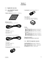
Page 9: ... 1 506 767 11 4 pin plug 1 Sony Part No 1 506 343 11 Plug holder 1 CCU 700A Sony Part No 2 990 242 01 CCU 700AP Sony Part No 3 170 078 01 Fuses CCU 700A 3 15 A 125 V 1 Sony Part No 1 532 745 11 6 3 A 125 V 1 Sony Part No 1 532 748 11 T1 AH 250 V 1 Sony Part No 1 576 225 41 CCU 700AP T1 AH 250 V 1 Sony Part No 1 576 225 41 T4 AH 250 V 1 Sony Part No 1 576 231 41 T3 15 AH 250 V 1 Sony Part No 1 576 ...

Page 10: ...p 75 Color bars for CCU 700AP B Y 700 mV p p 75 Color bars for CCU 700A 525 mV p p 75 Color bars for CCU 700AP CHARACTER 210 mV p p 300 mV p p sync WF 1 2 100 IRE 140 IRE ENC for CCU 700A 700 mV p p 1 0 V p p ENC for CCU 700AP PIX 1 2 140 IRE 1 0 V p p VBS 1 to 3 140 IRE 1 0 V p p SYNC 300 mV p p DIGITAL OUTPUT 1 2 3 When BKP 7311 is connected D1 format serial digital SMPTE 259 M ITU R BT 656 Inpu...

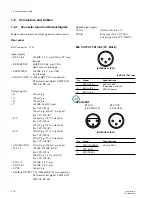
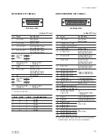
Page 11: ...Signal Specifications 1 5 5 V OUT Max 250 mA Fuse AT board 2 CAMERA No CK OUT 3 CAMERA No SPARE OUT 4 TALLY GND GND for TALLY 5 G TALLY OUT Q2841 NPN AT board ON GND Max 30 mA 6 R TALLY OUT Q2840 NPN AT board ON GND Max 30 mA 7 TALLY OUT R G TALLY OUT Q2842 NPN AT board ON GND Max 30 mA 8 CALL OUT Q1010 NPN AT board ON GND Max 30 mA 9 INCOM TALK G IN 2 10 INCOM TALK Y IN 20 dBu CARBON MIC 11 INCOM...

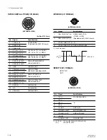
Page 12: ...IN ENG SYSTEM TALK 14 ENG T Y IN 0 dBu BALANCED 15 PROD T X IN PROD SYSTEM TALK 16 PROD T Y IN 0 dBu BALANCED 17 ENG G GND for ENG 18 NC No connection 19 PROD G GND for PROD 4 1 3 2 12 1 V 6 V R G B DC 0 2V WF MODE 4P FEMALE EXTERNAL VIEW No Signal Specifications 1 SEQ CONT OUT G OPEN COLLECTOR 2 SEQ CONT OUT X PNP NPN Selectable with S1102 VA board 3 STAIR CASE OUT X 3 4 STAIR CASE OUT G GND for ...

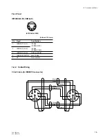
Page 13: ...ions 1 INCOM T IN Y 20 dBu CARBON MIC 2 INCOM T IN X 60 dBu DYNAMIC MIC 3 INCOM T IN G GND for INCOM 4 INCOM R OUT X Max 12 dBu 5 NC No connection 1 2 2 Cable Wiring CCA 5 Cable for REMOTE connector 1 2 Connectors and Cable Black White White Brown White Red Red Brown Brown Orange 1 2 3 4 8 5 6 7 1 2 3 4 8 5 6 7 ...

Page 14: ...2 3 SYNC BNC RTS IN 1 508 084 00 XLR 3P MALE or 3P FEMALE CANNON XLR 3 12C equivalent MIC CH1 CH2 1 508 083 00 XLR 3P FEMALE RTS OUT or 3P MALE CANNON XLR 3 11C equivalent REMOTE MIC 1 506 582 11 D SUB 15P MALE or 15P FEMALE JAE DA 15PF N equivalent REMOTE D SUB 25P MALE INTERCOM JAE DA 25PF N equivalent 25P FEMALE INTERCOM TALLY PGM 1 506 767 11 19P MALE MULTI 19P FEMALE supplied WF MODE 1 506 15...

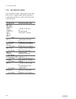
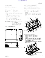
Page 15: ...YNAMIC OFF CARBON INTERCOM PUSH CAMERA CONTROL UNIT 400 424 132 Unit mm 57 2 465 481 1 3 3 Installation of BKP 7312 1 Set the S250 1 switch on the BKP 7312 to OFF 2 Remove the six screws B3x5 and then remove the rear panel 3 Disconnect the connector CN4 on the CN 1014 board and the connector CN3 on the CN 1049 board n When disconnecting the flexible card wires refer to 2 1 3 Disconnecting Connecti...

Page 16: ...P 7312 Shielding case A CN3 CN4 A Side Rear panel Ferrite core MB 563 board Coaxial cable CN12 9 Connect the other ends of the harnesses to the connec tors CN26 and CN28 on the MB 563 board respective ly 10 Connect the two flexible card wires to the connector CN4 on the CN 1014 board and the connector CN3 on the CN 1049 board n When connecting the flexible card wires refer to 2 1 3 Disconnecting C...

Page 17: ...1 set Applicable rack The depth is 660 830 mm 26 32 3 4 inches for 22 rail Installation Refer to the installation manual supplied with the RMM 30 n The slide rails of the RMM 30 is equivalent to the Accuride s 305A 22 If you use rails which are different in length we recommend the Accuride made 2 SUA 861 1 set Applicable rack Sony SU 860 only Installation Refer to the installation manual supplied ...

Page 18: ...TEL 704 588 5880 FAX 704 588 6316 Accuride 1930 Parco Avenue Ontario CA91761 TEL 714 923 9922 FAX 714 947 8586 WEST GERMANY Standard Praezision GmbH Postfach 1464 Werner von Siemens Strasse 16 18 6252 Diez Lahn West Germany TEL 6432 6080 FAX 6432 60820 UNITED KINGDOM Accuride Limited Lilliput Road Brackmills Industrial Estate Northampton NN4 OAR United Kingdom TEL 604 761111 FAX 604 767190 Install...

Page 19: ...e screws fixing the bracket 5 Fit the bracket to the rack using the two hexagonal socket head bolts Universal type Rack Wide type Rack 6 Pull out the outer rails 7 While pressing the stoppers slide the inner rails fully into the outer rails Have two or more persons to do this work 8 Secure the rack angles to the rack with the four screws M5x10 and the four ornamental washers ø5 1 3 Installation ...

Page 20: ...s recommended to turn on when either MSU or RCP is connected to CCU Factory setting is OFF S1002 5 CHARACTER OFF SELECT When the CHARACTER button on the RCP control panel is turned off the lamp goes out S1002 5 selects whether an error message is displayed in the auto setup and diagnosis modes or not OFF Normal mode A message is displayed only when an error occurs ON No message is displayed Factor...

Page 21: ...tting is CMD 1 ISR Interactive Status Report system S2061 INPUT SELECT 1CH 2CH Set this switch according to the intercom system in use to 1CH PROD or 2CH PROD ENG When set to 1CH the PROD producer line is automatically selected regardless of the settings of the camera intercom line selector rear panel and S2062 ENG PRIVATE PROD switch on the AT 88 board of the CCU Set S2341 INCOM MIX to OFF with S...

Page 22: ...T S2792 R TALLY POWER TTL Set these switches according to the specification of the R signal which is input at the INTERCOM TALLY PGM connector on the rear panel The relationship between the signal and switch setting is shown in the table S2821 G TALLY POWER CONTACT S2822 G TALLY POWER TTL Set these switches according to the specification of the G signal which is input at the INTERCOM TALLY PGM con...

Page 23: ...ower is supplied to the modulation circuit sending a prompter signal When set to RX power is supplied to the demodulation circuit receiving a prompter signal from the camera head Be sure to set this switch and S6 PROMPTER RF SELECT switch to the same mode Factory setting is TX S6 PROMPTER RF SELECT TX RX When this switch is set to TX a circuit sending an RF signal activates and when set to RX a ci...

Page 24: ... OFF marked position S1101 SEQ4 SEQ3 This switch selects the SEQ mode for a waveform monitor This is for an optional circuit When set to 3 SEQ3 three waveforms of R G and B are sequentially output When set to 4 SEQ4 four waveforms of R G B and Y are Factory setting is 3 SEQ3 If you use the SEQ4 mode please consult your service representative 12 5 5 12 VA S221 B Y SEL S126 ON OFF TEST S125 R Y SEL ...

Page 25: ... setting is 20H Set according to use S1961 SC STEP Used to adjust the subcarrier phase One step of this switch changes 90 degrees This switch activates only when the switch S1962 is LOCAL S1962 REMOTE LOCAL This switch selects whether the master setup unit MSU performs the following adjustments or the CCU 700A does H and SC phases synchronization with an external genlock signal NOTCH level and wid...

Page 26: ...e instead of a triaxial cable In this case use a camera equipped with the standalone unit available separately because a power is not supplied to the camera And a TRIAX to BNC conversion connector is necessary for the camera For the CCU the following modification is required Disconnect the RF cable from CN8 on the DM 94 board and reconnect it to CN9 1 5 Coax Connector ...

Page 27: ...it CNU 700 Master Setup Unit MSU 700 Video Selector VCS 700 Remote Control Panel RCP 700 701 RCP 720 721 RCP 740 741 CCA 5 Cable CCA 5 3 3 m CCA 5 10 10 m Triaxial Cable Connection cable between BVP and CCU Long Triax Unit BKP 7310 SDI Output Board BKP 7311 SDI Input Board BKP 7312 Sub Encode Unit BKP 7931 7931P Extension Board For CCU 700A CNU 700 BKP 7900 1 6 Peripheral Equipments and Accessorie...

Page 28: ...55CE CAMERA ADAPTOR CA 550 550P CCD UNIT OHB 400 400P OHB 500 500P OHB 550WS 550WSP OHB 750 750P OHB 750W 750WP STUDIO ZOOM LENS ELECTRONIC VIEWFINDER For BVP 700 700P TRIAX CABLE 2 or COAX CABLE TRIAX CABLE 2 TRIAX CABLE 2 COLOR VIDEO CAMERA BVP 500 500P BVP 700 700P 2 TRIAX CABLE LENGTH BVF 77 77CE BVF 7700 7700P CCD UNIT OHB 750 750P OHB 750W 750WP ENG EFP LENS 1 5 VF COLOR VIDEO CAMERA BVP 750...

Page 29: ... max 200m CCA 5 CABLE 1 CAMERA COMMAND NETWORK UNIT CNU 700 500 MASTER SETUP UNIT MSU 700 CAMERA CONTROL UNIT CCU 700A 700AP VIDEO SELECTOR VCS 700 PIX WF PIX 2 PIX 2 WF 2 WF 2 CAMERA CONTROL UNIT CCU 700A 700AP 1 CCA 5 CABLE LENGTH CCU CNU 200m RCP 740 1 RCP 720 1 RCP 700 1 CCU CNU 160m RCP 740 1 or RCP 720 1 RCP 700 1 CCU CNU 90m RCP 740 1 or RCP 720 1 RCP 740 1 or RCP 720 1 RCP 740 1 or RCP 720...

Page 30: ......

Page 31: ...d open the rear panel 2 Disconnect the eight connectors from the rear panel CN3 4 CN 1014 board CN17 18 CN 1015 board CN18 19 CN 1036 board CN3 CN 1049 board and RF connector 3 Disconnect the seven connectors CN10 12 16 17 20 21 24 from the MB 563 board M4 20 M4 20 Front panel CN12 CN10 CN 1014 board B3 5 B3 5 B3 5 B3 5 CN18 B3 5 CN4 CN16 CN21 CN20 CN17 CN19 CN18 MB 563 board CN24 CN 1049 board B3...

Page 32: ...ed with dust 1 Insert the flexible cable tightly into the connector so that the insulated surface blue colored of the cable is faced to the wider width of the connector flange 2 1 4 Installation of Rear Panel 1 Tighten the two screws 1 and 2 in numeral order then tighten the other four screws randomly 2 1 5 Replacement of TRIAX Connector 1 Remove the four screws Disconnect the connector CN1 on the...

Page 33: ...d side panels of a replacement power unit as illustrated MAIN CAMERA MAIN CAMERA Label MAIN fuse 2A 125V NTSC T2AH 250V PAL CAMERA fuse 6 3A 125V NTSC T3 15AH 250V PAL 4 Remove the blind plate of the replacement power unit then remove and discard the two fuses in the unit Put the supplied fuses into each fuse holder as the label indicates 5 After the fuses are replaced install the power unit and t...

Page 34: ... Warning Components marked are critical to safe operation Therefore specified parts should be used in the case of replacement 2 Standardization of Parts Some repair parts supplied by Sony differ from those used for the unit These are because of parts common ality and improvement Parts list has the present standardized repair parts 3 Stock of Parts Parts marked with o at SP Supply Code column of th...

Page 35: ...nt CCU 370 Checker is required When adjusting STAIR CASE adjustment connect the WF MODE connector of CCU 700A 700AP rear panel and remote control connector of waveform monitor with 3 pin cord Regarding the 3 pin cord refer to Section 1 Adjust the chrominance level at VIDEO OUT so that each beam spot should be positioned inside the color reproducibility frame using 1CV1602 and 1CV1603 on the VA 156...

Page 36: ...0m CAMERA CONTROL UNIT CCU 700A MASTER SETUP UNIT MSU 700 PIX Vectorscope Color monitor Waveform monitor 75Ω A ch REF IN COLOR VIDEO CAMERA BVP 700 BVP 500 STUDIO ZOOM LENS CCD UNIT OHB CCD UNIT OHB 600Ω GND GND X 600Ω GND GND Y X 600Ω GND GND Y X Signal generator 75Ω 75Ω Audio generator Audio generator Audio generator Total cable length less than 2 m Fig 1 Fig 2 Fig 3 ...

Page 37: ... goes off CLOSE button ON light up CAMERA HEAD CCU CIRCUIT ON OFF BLOCK DETAIL OFF button OFF light up KNEE OFF button OFF light up AUTO KNEE button OFF lamp goes off MATRIX OFF button OFF light up AUTO SETUP BLOCK LEVEL button OFF lamp goes off WHITE button OFF lamp goes off BLACK button OFF lamp goes off OTHERS GAMMA OFF button ON lamp goes off MASTER GAIN select button 0 2 Presetting of compens...

Page 38: ...rrier Balance Adjustment 3 5 5 C 1st AGC Adjustment 3 4 4 22 5MHz VCO DC Set Adjustment 1 3 5 2 C PLL Set Adjustment 2 3 5 7 R Y DEMOD Carrier Balance Adjustment 3 5 4 B Y Crosstalk Adjustment 3 5 6 B Y OUT Level Adjustment 3 4 9 Y OFFSET Adjustment 3 4 11 Y Output Level Adjustment 3 6 1 Return Video Carrier Frequency Adjustment 3 6 2 Return Video Deviation Adjustment 3 6 3 Return Video Mix Ratio ...

Page 39: ...ange due to 1RV1961 SC FINE VA 156 board is 100 2 3 3 Video Signal System Adjustment 12 5 5 12 VA TP26 E9 TP27 CV651 CV125 RV670 RV145 RV931 CV931 CV521 CV1 RV533 RV20 RV841 CV841 RV361 RV280 RV1011 CV1011 CV341 RV360 CV221 RV1603 CV1602 RV221 TP25 E6 CV1603 RV1604 RV125 S221 B Y SEL S126 ON OFF TEST S125 R Y SEL Y SEL S1 RV1 TP34 E10 TP1 RV341 RV10 RV11 RV13 TP4 RV342 RV270 TP7 RV135 TP5 RV12 TP2...

Page 40: ...SC B 9 cycles For PAL B 2 25 0 2 µs 3 3 3 SYNC Phase Adjustment Rank B Equipment Waveform monitor To be extended VA 156 board Preparation MASTER PEDESTAL volume MSU 700 99 Test point VBS 1 OUT connector CCU rear panel Adjusting point 1RV1782 SYNC PHASE VA 156 board 1RV1783 SYNC WIDTH VA 156 board Specification For NTSC T1 1 5 0 1 µs 1RV1782 T2 4 7 0 1 µs 1RV1783 For PAL T1 1 65 0 1 µs 1RV1782 T2 4...

Page 41: ...g the SC H Phase adjust 1RV1963 H PHASE FINE VA 156 board If not need set 1RV1963 to mechanical center 3 3 Video Signal System Adjustment 12 5 5 12 VA TP26 E9 TP27 CV651 CV125 RV670 RV145 RV931 CV931 CV521 CV1 RV533 RV20 RV841 CV841 RV361 RV280 RV1011 CV1011 CV341 RV360 CV221 RV1603 CV1602 RV221 TP25 E6 CV1603 RV1604 RV125 S221 B Y SEL S126 ON OFF TEST S125 R Y SEL Y SEL S1 RV1 TP34 E10 TP1 RV341 ...

Page 42: ...TP27 CV651 CV125 RV670 RV145 RV931 CV931 CV521 CV1 RV533 RV20 RV841 CV841 RV361 RV280 RV1011 CV1011 CV341 RV360 CV221 RV1603 CV1602 RV221 TP25 E6 CV1603 RV1604 RV125 S221 B Y SEL S126 ON OFF TEST S125 R Y SEL Y SEL S1 RV1 TP34 E10 TP1 RV341 RV10 RV11 RV13 TP4 RV342 RV270 TP7 RV135 TP5 RV12 TP2 E1 S2032 CB MODE LV1011 RV271 RV272 RV137 RV136 RV2032 RV651 RV521 RV343 RV660 RV530 RV350 TP8 RV344 TP9 ...

Page 43: ...generator To be extended VA 156 board Preparation S1 Y SEL VA 156 AUX BARS button MSU 700 OFF Connect CCU 370 Checker to CN3 VA 156 board Feed the H SWEEP signal of video signal generator to R terminal Adjustment procedure Adjust the following controls nutil the specifications are satisfied Test point rear panel Adjustment point VBS1 VBS1 OUT 1CV1501 VBS2 VBS2 OUT 1CV1602 VBS3 VBS3 OUT 1CV1603 Not...

Page 44: ...ope 75 CAL 3 3 Video Signal System Adjustment 12 5 5 12 VA TP26 E9 TP27 CV651 CV125 RV670 RV145 RV931 CV931 CV521 CV1 RV533 RV20 RV841 CV841 RV361 RV280 RV1011 CV1011 CV341 RV360 CV221 RV1603 CV1602 RV221 TP25 E6 CV1603 RV1604 RV125 S221 B Y SEL S126 ON OFF TEST S125 R Y SEL Y SEL S1 RV1 TP34 E10 TP1 RV341 RV10 RV11 RV13 TP4 RV342 RV270 TP7 RV135 TP5 RV12 TP2 E1 S2032 CB MODE LV1011 RV271 RV272 RV...

Page 45: ...s follows S1362 Q U ON OFF VA 156 board ON Re check 3 3 13 Color Vector Adjustment For NTSC For PAL R MG CY G YL B R MG YL B CY G 3 3 13 Color Vector Adjustment Rank B Equipment Vectorscope EXT REF mode To be extended VA 156 board Preparation GAIN switch Vectorscope 75 CAL Adjust the PHASE control on the vectorscope so that the burst spot is overlapped to the 75 axis BARS button MSU 700 ON S1361 I...

Page 46: ...6 board so that the signal level at VBS 1 OUT connector CCU rear panel is not fluctuated even if CONTRAST button MSU 700 is turned ON or OFF Note After the adjustment re check 3 3 15 CONTRST Y Level Adjustment A 3 3 15 CONTRAST Y Level Adjustment Rank B Equipment Oscilloscope Waveform monitor To be extended VA 156 board Preparation 1 BARS button MSU 700 OFF 2 S126 TEST ON OFF VA 156 board ON 3 CON...

Page 47: ... point 1RV1 Y BLK VA 156 board Specification For NTSC A 0 1 IRE For PAL A 0 7 mV 3 3 Video Signal System Adjustment 12 5 5 12 VA TP26 E9 TP27 CV651 CV125 RV670 RV145 RV931 CV931 CV521 CV1 RV533 RV20 RV841 CV841 RV361 RV280 RV1011 CV1011 CV341 RV360 CV221 RV1603 CV1602 RV221 TP25 E6 CV1603 RV1604 RV125 S221 B Y SEL S126 ON OFF TEST S125 R Y SEL Y SEL S1 RV1 TP34 E10 TP1 RV341 RV10 RV11 RV13 TP4 RV3...

Page 48: ...CV221 RV1603 CV1602 RV221 TP25 E6 CV1603 RV1604 RV125 S221 B Y SEL S126 ON OFF TEST S125 R Y SEL Y SEL S1 RV1 TP34 E10 TP1 RV341 RV10 RV11 RV13 TP4 RV342 RV270 TP7 RV135 TP5 RV12 TP2 E1 S2032 CB MODE LV1011 RV271 RV272 RV137 RV136 RV2032 RV651 RV521 RV343 RV660 RV530 TP12 RV350 TP8 RV344 TP9 E2 RV351 RV352 RV353 RV531 RV532 TP31 TP32 TP14 TP13 TP30 RV2034 E8 RV2033 RV2035 RV2036 RV2031 RV2037 S189...

Page 49: ...oard so that the beam spot of black level sit at the nearly center of the vectorscope Note After the adjustment set as follows GAIN switch Vectorscope 75 CAL MASTER BLACK control MSU 700 0 3 3 22 R Y B Y OUT Level Adjustment Rank A Equipment Oscilloscope To be extended VA 156 board Preparation BARS button MSU 700 ON R Y OUT connector CCU rear panel 75 Z Terminated B Y OUT connector CCU rear panel ...

Page 50: ...761 WF1 VIDEO LEVEL VA 156 board Specification For NTSC A 100 1 IRE For PAL A 700 7 mV 3 3 24 PIX 1 OUT Level Adjustment Rank B Equipment Waveform monitor To be extended VA 156 board Preparation BARS button RCP 74x ON MONITOR SELECT button RCP 74x ENC PIX 1 OUT connector CCU rear panel 75 Z Terminated Test point PIX 1 OUT connector CCU rear panel Adjusting point 1RV931 PIX1 VIDEO LEVEL VA 156 boar...

Page 51: ...V 3 3 25 WF 2 OUT Level Adjustment Rank A Equipment Waveform monitor To be extended VA 156 board Preparation BARS button MSU 700 ON WAVEFORM MONITOR button MSU 700 ENC WF 2 OUT connector CCU rear panel 75 Z Terminated Test point WF 2 OUT connector CCU rear panel Adjusting point 1RV841 WF2 VIDEO LEVEL VA 156 board Specification For NTSC A 100 1 IRE For PAL A 700 7 mV A A For NTSC For PAL 12 5 5 12 ...

Page 52: ...4 RV125 S221 B Y SEL S126 ON OFF TEST S125 R Y SEL Y SEL S1 RV1 TP34 E10 TP1 RV341 RV10 RV11 RV13 TP4 RV342 RV270 TP7 RV135 TP5 RV12 TP2 E1 S2032 CB MODE LV1011 RV271 RV272 RV137 RV136 RV2032 RV651 RV521 RV343 RV660 RV530 TP12 RV350 TP8 RV344 TP9 E2 RV351 RV352 RV353 RV531 RV532 TP31 TP32 TP14 TP13 TP30 RV2034 E8 RV2033 RV2035 RV2036 RV2031 RV2037 S1891 H BLK RV1892 S2301 SKIN SIG RV1782 RV1783 RV...

Page 53: ...nt set as follows WAVWFORM MONITOR button MSU 700 ENC For NTSC For PAL A A 3 3 Video Signal System Adjustment 3 3 29 B Level Adjustment Rank A Equipment Waveform monitor To be extended VA 156 board Preparation BARS button MSU 700 ON Test point WF 2 OUT connector CCU rear panel Adjustment Procedure 1 WAVEFORM MONITOR button MSU 700 B 2 Adjusting point 1RV270 B MATRIX BAL VA 156 board Specification ...

Page 54: ...CV1011 CV341 RV360 CV221 RV1603 CV1602 RV221 TP25 E6 CV1603 RV1604 RV125 S221 B Y SEL S126 ON OFF TEST S125 R Y SEL Y SEL S1 RV1 TP34 E10 TP1 RV341 RV10 RV11 RV13 TP4 RV342 RV270 TP7 RV135 TP5 RV12 TP2 E1 S2032 CB MODE LV1011 RV271 RV272 RV137 RV136 RV2032 RV651 RV521 RV343 RV660 RV530 TP12 RV350 TP8 RV344 TP9 E2 RV351 RV352 RV353 RV531 RV532 TP31 TP32 TP14 TP13 TP30 RV2034 E8 RV2033 RV2035 RV2036...

Page 55: ... 156P board 3 3 Video Signal System Adjustment 12 5 5 12 VA TP26 E9 TP27 CV651 CV125 RV670 RV145 RV931 CV931 CV521 CV1 RV533 RV20 RV841 CV841 RV361 RV280 RV1011 CV1011 CV341 RV360 CV221 RV1603 CV1602 RV221 TP25 E6 CV1603 RV1604 RV125 S221 B Y SEL S126 ON OFF TEST S125 R Y SEL Y SEL S1 RV1 TP34 E10 TP1 RV341 RV10 RV11 RV13 TP4 RV342 RV270 TP7 RV135 TP5 RV12 TP2 E1 S2032 CB MODE LV1011 RV271 RV272 R...

Page 56: ...EL Y SEL S1 RV1 TP34 E10 TP1 RV341 RV10 RV11 RV13 TP4 RV342 RV270 TP7 RV135 TP5 RV12 TP2 E1 S2032 CB MODE LV1011 RV271 RV272 RV137 RV136 RV2032 RV651 RV521 RV343 RV660 RV530 TP12 RV350 TP8 RV344 TP9 E2 RV351 RV352 RV353 RV531 RV532 TP31 TP32 TP14 TP13 TP30 RV2034 E8 RV2033 RV2035 RV2036 RV2031 RV2037 S1891 H BLK RV1892 S2301 SKIN SIG RV1782 RV1783 RV1891 E7 S1102 SEQ ON S1101 SEQ RV1781 RV1967 RV1...

Page 57: ... 94 board Adjusting point 1LV1 Y RF TUNE DM 94 board Specification Level A maximum level 3 4 Y Cable Compensation System Adjustment 12 5 5 12 DM E15 E6 E9 TP18 TP12 TP24 TP23 E16 TP25 TP16 TP26 TP10 RV19 RV20 TP20 E11 CV1 TP21 RV21 CV3 CV2 LV2 RV22 LV3 E13 TP22 E10 RV8 RV7 RV6 TP9 RV24 RV3 TP6 RV11 RV16 RV18 RV15 RV14 RV13 TP15 E8 E12 TP14 RV5 RV2 RV4 TP8 TP7 TP4 TP1 E4 TP13 E7 E1 TP22 RV10 LV1 TP...

Page 58: ...est point TP8 GND E2 DM 94 board Adjusting point 1RV5 SYNC S H DM 94 board Specification T 1 3 0 1 µs 3 4 Y Cable Compensation System Adjustment 12 5 5 12 DM E15 E6 E9 TP18 TP12 TP24 TP23 E16 TP25 TP16 TP26 TP10 RV19 RV20 TP20 E11 CV1 TP21 RV21 CV3 CV2 LV2 RV22 LV3 E13 TP22 E10 RV8 RV7 RV6 TP9 RV24 RV3 TP6 RV11 RV16 RV18 RV15 RV14 RV13 TP15 E8 E12 TP14 RV5 RV2 RV4 TP8 TP7 TP4 TP1 E4 TP13 E7 E1 TP2...

Page 59: ...dure Confirm that the sample pulses have six pulses in both odd and even fields If not met adjust 1RV3 SAMPLE GATE DM 94 board so that the sample pulses have six pulses in both odd and even fields 3 4 5 Sample Pulse Width Adjustment Rank B Equipment Oscilloscope To be extended DM 94 board Test point TP7 GND E2 DM 94 board Adjusting point 1RV4 SAMPLE S H DM 94 board Specification T 40 0 2 0 µs 3 4 ...

Page 60: ...djust 1RV8 Y CAR LEVEL DM 94 board so that the signal level of V sample pulse is maximum Note After the adjustment set as follows S3 Y 2nd AGC DM 94 board ON V maximum A 3 4 7 22 5MHz Carrier Level Adjustment Rank B Equipment Oscilloscope To be extended DM 94 board Test point TP10 GND E5 DM 94 board Adjusting point 1RV7 Y CARR LEVEL DM 94 board Specification A 400 20 mV p p BW LIMIT Oscilloscope O...

Page 61: ... point TP11 GND E3 DM 94 board Adjusting point 1RV24 Y OFFSET ADJ DM 94 board Specification A 0 3 mV 3 4 Y Cable Compensation System Adjustment 12 5 5 12 DM E15 E6 E9 TP18 TP12 TP24 TP23 E16 TP25 TP16 TP26 TP10 RV19 RV20 TP20 E11 CV1 TP21 RV21 CV3 CV2 LV2 RV22 LV3 E13 TP22 E10 RV8 RV7 RV6 TP9 RV24 RV3 TP6 RV11 RV16 RV18 RV15 RV14 RV13 TP15 E8 E12 TP14 RV5 RV2 RV4 TP8 TP7 TP4 TP1 E4 TP13 E7 E1 TP22...

Page 62: ... 94 board Adjusting point 1RV9 Y LEVEL DM 94 board Specification A 707 7 mV p p 3 4 Y Cable Compensation System Adjustment 3 5 CHROMA Cable Compensation System Adjustment 12 5 5 12 DM E15 E6 E9 TP18 TP12 TP24 TP23 E16 TP25 TP16 TP26 TP10 RV19 RV20 TP20 E11 CV1 TP21 RV21 CV3 CV2 LV2 RV22 LV3 E13 TP22 E10 RV8 RV7 RV6 TP9 RV24 RV3 TP6 RV11 RV16 RV18 RV15 RV14 RV13 TP15 E8 E12 TP14 RV5 RV2 RV4 TP8 TP7...

Page 63: ...cation Adjust so that the waveform level of SAMPLE pulse is maximum Note After the adjustment set as follows S4 C 2nd AGC DM 94 board ON A GND 3 5 2 C PLL Set Adjustment Rank C Note Make sure that 45 MHz frequency on the MD board camera is correct Equipment Oscilloscope To be extended DM 94 board Test point TP15 GND E8 DM 94 board Adjusting point 1RV14 PLL SET DM 94 board Specification A 0 30 mV d...

Page 64: ...oint TP17 GND E3 DM 94 board Adjusting point 1RV13 OFFSET ADJ DM 94 board Specification A 0 3 mV 3 5 5 C 1st AGC Adjustment Rank B Equipment Oscilloscope To be extended DM 94 board Preparation S1 AUTO MANU DM 94 board AUTO S4 C 2nd AGC DM 94 board OFF Test point TP17 GND E3 DM 94 board Adjusting point 1RV10 C AGC CONT DM 94 board Specification A 350 20 mV 3 5 CHROMA Cable Compensation System Adjus...

Page 65: ...sting point 1RV12 B Y LEVEL DM 94 board Specification A 355 5 mV p p 3 5 CHROMA Cable Compensation System Adjustment 12 5 5 12 DM E15 E6 E9 TP18 TP12 TP24 TP23 E16 TP25 TP16 TP26 TP10 RV19 RV20 TP20 E11 CV1 TP21 RV21 CV3 CV2 LV2 RV22 LV3 E13 TP22 E10 RV8 RV7 RV6 TP9 RV24 RV3 TP6 RV11 RV16 RV18 RV15 RV14 RV13 TP15 E8 E12 TP14 RV5 RV2 RV4 TP8 TP7 TP4 TP1 E4 TP13 E7 E1 TP22 RV10 LV1 TP3 TP2 E2 TP5 TX...

Page 66: ... AGC DM 94 board ON Test point TP19 GND E3 DM 94 board Adjusting point 1RV17 R Y LEVEL DM 94 board Specification A 355 5 mV 3 5 CHROMA Cable Compensation System Adjustment 12 5 5 12 DM E15 E6 E9 TP18 TP12 TP24 TP23 E16 TP25 TP16 TP26 TP10 RV19 RV20 TP20 E11 CV1 TP21 RV21 CV3 CV2 LV2 RV22 LV3 E13 TP22 E10 RV8 RV7 RV6 TP9 RV24 RV3 TP6 RV11 RV16 RV18 RV15 RV14 RV13 TP15 E8 E12 TP14 RV5 RV2 RV4 TP8 TP...

Page 67: ...5 MHz 3 6 RETURN VIDEO Cable Compensation System Adjustment 3 6 1 Return Video Carrier Frequency Adjustment Rank C Equipment Spectrum analyzer To be extended DM 94 board Preparation BARS button MSU 700 OFF TEST 2 button MSU 700 ON Connect VBS 1 OUT connector and RET 1 IN connector on CCU 700A 700AP rear panel with BNC cable Test point TP21 GND E11 DM 94 board Adjusting point 1CV1 RET FREQ DM 94 bo...

Page 68: ... After adjustment set the MIX VF switch BVP rear panel to OFF 3 6 RETURN VIDEO Cable Compensation System Adjustment 12 5 5 12 DM E15 E6 E9 TP18 TP12 TP24 TP23 E16 TP25 TP16 TP26 TP10 RV19 RV20 TP20 E11 CV1 TP21 RV21 CV3 CV2 LV2 RV22 LV3 E13 TP22 E10 RV8 RV7 RV6 TP9 RV24 RV3 TP6 RV11 RV16 RV18 RV15 RV14 RV13 TP15 E8 E12 TP14 RV5 RV2 RV4 TP8 TP7 TP4 TP1 E4 TP13 E7 E1 TP22 RV10 LV1 TP3 TP2 E2 TP5 TX ...

Page 69: ...d CCU 700A 700AP AUTO S2 CABLE LENGTH DM 94 board CCU 700A 700AP 0 3 7 PROMPT VIDEO Cable Compensation System Adjustment 3 7 1 TX PROMPT VIDEO Demodulation Adjustment Rank B Note When adjusting this step the length of triaxial cable is required less than 500 m Equipment Oscilloscope Video signal generator To be extended DM 94 board Preparation S4 CCU CAM CAM CCU MD 83 board BVP side CCU CAM Connec...

Page 70: ... triaxial cable is required less than 500 m Adjustment of BVP 700 700P must be completed Equipment Oscilloscope Video signal generator SWEEP 10 STEP signal To be extended DM 94 board Preparation S4 CCU CAM CAM CCU MD 83 board BVP side CAM CCU Remove the green harness of MPX filter from CN35 PROMPT connector on DM 97 board BVP side And connect its harness to CN27 PROMPT REVERSE MB 430 board BVP sid...

Page 71: ... AGC DLY DM 94 board counter clockwise slowly from the right most position and stop where the V SYNC portion at waveform becomes flat Take care not to over turn Note After the adjustment set the switches as follows S4 CCU CAM CAM CCU switch MD 83 board BVP side CCU CAM Return the green harness of MPX filter to CN35 PROMPT connector on DM 97 board BVP side S5 TX RX switch DM 94 board TX S6 TX RX sw...

Page 72: ...edure Adjust 1RV23 PROMPT LEVEL DM 94 board so that the video level at pin D34 GND pin C34 exten sion board is 2 00 0 05 V p p Note After the adjustment set the switches as follows S4 CCU CAM CAM CCU switch MD 83 board BVP side CCU CAM Return the green harness of MPX filter to CN35 PROMPT connector on DM 97 board BVP side S5 TX RX switch DM 94 board TX S6 TX RX switch DM 94 board TX Remove the BNC...

Page 73: ...e DC voltage of 2 5 0 05 V to the pin C19 extension board 3 8 TRIAX Interface System Adjustment S1006 S1007 REMOTE MODE 1 REMOTE MODE 2 E1000 TP1001 TP22 TP23 S1001 MODE1 S1002 MODE2 TP21 E2 E20 TTL POWER S2822 TTL S2792 CONTACT POWER S2821 G TALLY S2791 Y TALLY POWER POWER RV2432 RV2431 S2081 RV2310 RV2382 TP47 TP48 E12 S2082 S2083 S2061 S2341 RV2301 RV2302 TP10 TP13 TP9 TP15 TP17 RV501 RV401 TP1...

Page 74: ...he AT 88 board so that the A and B are 6 0 0 4 kHz 3 8 2 INCOM 1 Deviation Adjustment Rank C Equipment Spectrum analyzer Oscilloscope Audio generator To be extended AT 88 board Preparation INCOM 1 PROD ENG switch BVP rear panel ENG Test point TP3 GND E1 AT 88 board Adjusting point 1RV41 INCOM 1 DEV AT 88 board Specification A B 6 0 0 4 kHz Adjustment Procedure 1 For 4W intercom system Feed the 400...

Page 75: ...EMOTE MODE 1 REMOTE MODE 2 E1000 TP1001 TP22 TP23 S1001 MODE1 S1002 MODE2 TP21 E2 E20 TTL POWER S2822 TTL S2792 CONTACT POWER S2821 G TALLY S2791 Y TALLY POWER POWER RV2432 RV2431 S2081 RV2310 RV2382 TP47 TP48 E12 S2082 S2083 S2061 S2341 RV2301 RV2302 TP10 TP13 TP9 TP15 TP17 RV501 RV401 TP12 S301 RV201 RV301 LV1 LV21 TP1 TP2 TP7 RV101 RV81 LV81 RV61 LV61 RV41 LV41 TP5 TP4 TP3 TP6 T401 T501 TP16 TP...

Page 76: ... 0 02 V dc 3 Set the input range of oscilloscope to AC mode and adjust a blue core of 1T401 AT 88 board so that the sine wave is minimum 4 Repeat procedure 2 1 24 0 02 V dc GND 3 8 6 INCOM 1 Level Adjustment Rank B Equipment Oscilloscope Audio generator To be extended AT 88 board Preparation MIC 1 ON OFF switch BVP rear panel ON Extend the AU 177 board BVP camera with extension board EX 439 Test p...

Page 77: ...edure 2 3 8 TRIAX Interface System Adjustment S1006 S1007 REMOTE MODE 1 REMOTE MODE 2 E1000 TP1001 TP22 TP23 S1001 MODE1 S1002 MODE2 TP21 E2 E20 TTL POWER S2822 TTL S2792 CONTACT POWER S2821 G TALLY S2791 Y TALLY POWER POWER RV2432 RV2431 S2081 RV2310 RV2382 TP47 TP48 E12 S2082 S2083 S2061 S2341 RV2301 RV2302 TP10 TP13 TP9 TP15 TP17 RV501 RV401 TP12 S301 RV201 RV301 LV1 LV21 TP1 TP2 TP7 RV101 RV81...

Page 78: ...mV p p 3 8 9 MIC 1 Demod Adjustment Rank C Note Perform the adjustment only when replacing 1T201 AT 88 board Equipment Oscilloscope Audio generator To be extended AT 88 board Preparation Extend the AU 177 board BVP camera with extension board EX 439 S1003 MIC 1 GAIN switch AT 88 board MIN Test point TP8 GND E10 AT 88 board Adjustment Procedure 1 Feed the 1kHz 270 mV p p sine wave to pin 66 X pin 6...

Page 79: ... p S1006 S1007 REMOTE MODE 1 REMOTE MODE 2 E1000 TP1001 TP22 TP23 S1001 MODE1 S1002 MODE2 TP21 E2 E20 TTL POWER S2822 TTL S2792 CONTACT POWER S2821 G TALLY S2791 Y TALLY POWER POWER RV2432 RV2431 S2081 RV2310 RV2382 TP47 TP48 E12 S2082 S2083 S2061 S2341 RV2301 RV2302 TP10 TP13 TP9 TP15 TP17 RV501 RV401 TP12 S301 RV201 RV301 LV1 LV21 TP1 TP2 TP7 RV101 RV81 LV81 RV61 LV61 RV41 LV41 TP5 TP4 TP3 TP6 T...

Page 80: ...oard is 1100 50 mV p p 3 8 11 MIC 2 Demod Adjustment Rank C Note Perform the adjustment only when replacing 1T301 AT 88 board Equipment Oscilloscope Audio generator To be extended AT 88 board Preparation Extend the AU 177 board BVP camera with extension board EX 439 S1004 MIC 2 GAIN switch AT 88 board MIN Test point TP11 GND E10 AT 88 board Adjustment Procedure 1 Feed the 1 kHz 220 mV p p sine wav...

Page 81: ...e To be extended AT 88 board Test point TP6 GND E2 AT 88 board Adjusting point 1LV101 5 6 MHz TUNE AT 88 board Specification 0 20 0 02 V dc 3 8 TRIAX Interface System Adjustment E1000 TP1001 TP22 TP23 S1001 MODE1 S1002 MODE2 TP21 E2 E20 S2081 RV2382 TP47 TP48 E12 S2082 S2083 S2061 S2341 RV2301 RV2302 TP10 TP13 TP9 TP15 TP17 RV501 RV401 TP12 S301 RV201 RV301 LV1 LV21 TP1 TP2 TP7 RV101 RV81 LV81 RV6...

Page 82: ...Fig 1 Refer to 3 1 4 Audio connection 2 Adjust the output of audio generator so that the level at TP43 GND E1 on the AT 88 board is 200 mV p p 3 1RV2310 INCOM FP LEVEL AT 88 board fully clockwise 2 4 Confirm that the signal level at pin A67 extension board is 9 0 0 5 V p p 3 9 Intercom System Adjustment 3 9 1 INCOM T Level Set Rank C Equipment Oscilloscope Audio generator Preparation MIC switch CC...

Page 83: ...o 3 1 4 Audio connection 2 Adjust the output of audio generator so that the level at TP44 GND E1 on the AT 88 board is 200 mV p p 3 When turning 1RV2342 PGM MIX AT 88 board fully clockwise 2 check the output level at TP48 GND E12 AT 88 board is 200 20 mV p p 4 Readjust 1RV2342 PGM MIX AT 88 board so that the level at the same test point is 100 10 mV p p Notes this specification is for guidance whe...

Page 84: ...00A 700AP 2 Adjust 1RV2452 ENG 2W CANCEL AT 88 board so that the audio level at TP46 GND E11 AT 88 board is minimum 3 10 2W Intercom System Adjustment 3 10 1 ENG Level Adjustment n Perform the following adjustment to much the input level of the camera system Rank C Equipment Oscilloscope Audio generator To be extended AT 88 board Preparation S2491 INCOM 1 SELECT AT 88 board 2W Test point TP46 GND ...

Page 85: ...C switch CCU front panel CARBON INCOM PROD PRIV ENG switch AT 88 board panel PROD S2241 INCOM 2 SELECT AT 88 board 2W Connect between pin B70 and pin D70 extension board with 600 Z resistor Test point TP43 GND E10 AT 88 board Adjustment Procedure 1 Feed the 1 kHz 220 mV p p sine wave to INCOM connector CCU 700A 700AP 2 Adjust 1RV2212 PROD 2W CANCEL AT 88 board so that the audio level at TP43 GND E...

Page 86: ...inter com is RTS system Also this information is only for repair purpose Rank C Equipment Oscilloscope Audio generator To be extended AT 88 board Preparation MIC switch CCU front panel CARBON INCOM PROD PRIV ENG switch AT 88 board panel ENG S2491 INCOM 1 SELECT AT 88 board RTS Connect between pin D71 and pin B72 extension board with 200 Z resistor Test point TP46 GND E11 AT 88 board Adjustment Pro...

Page 87: ... POWER MAIN CAMERA SHORT OPEN POWER 1 ON OFF OFF lights up goes out goes out lights up goes out ON OFF ON lights up goes out goes out goes out lights up red ON ON OFF lights up lights up goes out lights up goes out ON ON ON lights up lights up goes out goes out lights up green ON ON ON 2 lights up goes out goes out lights up lights up red 1 When video camera BVP 700 700P is connected 2 The conditi...

Page 88: ......

Page 89: ... 5 25V Earth Ground The material contained in this manual consists of information that is the property of Sony Corporation and is intended solely for use by the purchasers of the equipment described in this manual Sony Corporation expressly prohibits the duplication of any portion of this manual or the use thereof for any purpose other than the operation or maintenance of the equipment described i...

Page 90: ...Printed in U S A Sony Corporation 1998 4 76 Broadcasting Professional Systems Company 1996 CCU 700A UC CCU 700AP CE E 3 189 223 13 Volume 1 ...

Reviews: