background image

SIGNAL PROCESSING UNIT

PFV-SP3100

BACKUP POWER SUPPLY UNIT

HK-PSU01

INSTALLATION MANUAL
1st Edition
Serial No. 10001 and Higher (PFV-SP3100)
Serial No. 10001 and Higher (HK-PSU01)

Summary of Contents for HK-PSU01

Page 1: ...SIGNAL PROCESSING UNIT PFV SP3100 BACKUP POWER SUPPLY UNIT HK PSU01 INSTALLATION MANUAL 1st Edition Serial No 10001 and Higher PFV SP3100 Serial No 10001 and Higher HK PSU01 ...

Page 2: ...ente uniquement For the U S A PFV SP3100 Attention when the product is installed in Rack 1 Prevention against overloading of branch circuit When this product is installed in a rack and is supplied power from an outlet on the rack please make sure that the rack does not overload the supply circuit 2 Providing protective earth When this product is installed in a rack and is supplied power from an ou...

Page 3: ...ecommended Power Cord 1 1 E 1 3 Installation Space 1 2 E 1 4 Installing Removing Optional Power Supply Unit 1 3 E 1 5 Installing Optional Board 1 4 E 1 6 Rack Mounting 1 6 E 1 6 1 Notes on Rack Mounting 1 6 E 1 6 2 Rack Mounting Procedure 1 6 E 1 7 Matching Connector Cable 1 8 E 1 8 Signal Inputs Outputs 1 8 E 2 Service Overview 2 1 Cleaning the Filter 2 1 E 2 2 Periodic Replacement Parts to Be Re...

Page 4: ... PFV SP3100 This manual describes the notes on operating the locations and functions of parts and controls of PFV SP3100 Maintenance Manual Available on request This manual describes the information for periodic maintenance and detailed service If this manual is required please contact your local Sony Sales Office Service Center Semiconductor Pin Assignments CD ROM Available on request This Semico...

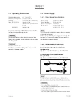
Page 5: ...V Power frequency 50 Hz or 60 Hz Current consumption 1 0 to 0 5 A Rush current AC 100 V IN 10 A AC 240 V IN 33 A n AC power supply is required a capacity which is commen surate with rush current If the capacity of the AC power supply is not enough the breaker of AC power on the supply side may operate or this unit may not operate normally 1 2 2 Recommended Power Cord For customers in the U S A and...

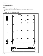
Page 6: ... block the ventilation holes of the unit Both of the front and rear sides must be at least 20 cm away from the walls for ventilation and mainte nance The outer dimensions of PFV SP3100 are as shown here 1 3 Installation Space Unit mm 440 482 43 6 550 ...

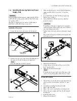
Page 7: ...mplete contact resistance of the connector increases and that may cause damage and smoke Tighten firmly the screws that secure the power supply units Do not turn on the power until the power supply units are firmly secured 6 Reinstall the front panel 7 Connect the power cord and set the power switch to the I position ON 8 Make sure that the indicator lights n If the indicator does not light turn o...

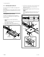
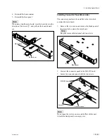
Page 8: ... Turn off both of the power switches when the backup power supply unit is installed 2 Remove the front panel Refer to Section 1 4 3 Loosen the four screws and remove the board retainer B 3x8 with stopper Board retainer Power switches B 3x8 with stopper 4 3 2 1 1 Board lever Slot label Board retainer Board lever Board guides Main board Slot 4 Slot 3 Slot 2 Slot 1 4 Insert the main board fully into ...

Page 9: ...st be installed to the slot which contains the main board 1 Remove the two screws and remove the blank panel of the slot which contains the main board n Keep the removed blank panel and two screws 2 Connect the connector panel to the MB 992 board 3 Secure the connector panel with the two screws n Do not open the slot for an air cooled effect of this unit Attach the blank panel to an empty slot Bla...

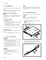
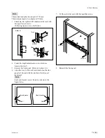
Page 10: ... using a rack mounting kit other than the specified one Components of RMM 10 Rack brackets 2 pcs Rack mounting adaptor right 1 pc Including two screws B 4x6 7 682 560 09 Rack mounting adaptor left 1 pc Including two screws B 4x6 7 682 560 09 Rack bracket fixing screws B 4x6 7 682 560 09 6 pcs Adaptor fixing screws B 4x10 7 682 560 10 6 pcs Required other parts To mount the unit on the rack the fol...

Page 11: ...rews which are loosened in step 2 5 Remove the front panel Refer to Section 1 4 6 Align the crook of the each rack bracket on the side panels of the unit with the rail then slide the unit backward n Each rack bracket covers the rails as shown in the figure below 1 6 Rack Mounting Front Rear B 4x10 1U 31 75 31 75 RMM 10 B 4x10 Rail Rail Rack bracket Rack bracket 7 Fix the unit to the rack with the ...

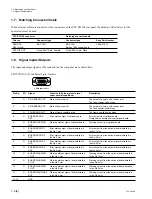
Page 12: ...output of optional board Warning output from optional board OUT 6 O BOARD ERROR 1 Error status output of board installed in Error output from the optional board installed in OUT the No 1 slot the No 1 slot 7 O BOARD ERROR 2 Error status output of board installed in Error output from the optional board installed in OUT the No 2 slot the No 2 slot 8 O BOARD ERROR 3 Error status output of board insta...

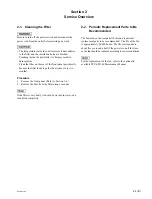
Page 13: ...er dust once every two months Procedure 1 Remove the front panel Refer to Section 1 4 2 Remove the dust from the filter using a vacuum n If the filter is very dusty it should be washed in water and then dried completely 2 2 Periodic Replacement Parts to Be Recommended The fan used on the rear panel of this unit is periodic replacement parts to be recommended The life of the fan is approximately 50...

Page 14: ......

Page 15: ...é de Sony Corporation Sony Corporation interdit formellement la copie de quelque partie que ce soit de ce manuel ou son emploi pour tout autre but que des opérations ou entretiens de l équipement à moins d une permission écrite de Sony Corporation Das in dieser Anleitung enthaltene Material besteht aus Informationen die Eigentum der Sony Corporation sind Die Sony Corporation untersagt ausdrücklich...

Page 16: ...Printed in Japan Sony Corporation 2002 7 22 B P Company 2002 PFV SP3100 SY J E 3 690 471 01 ...

Reviews: