background image

Sony Corporation

G:\#sagyou\Sony\0811\4291686111\4291686111HXCD70SY\01GB01COV\01GB12BCV-SYM.fm

masterpage:BackCover

HXC-D70

4-291-686-

11 (1)

Printed in Japan

HD Color Camera

Operating Instructions

Before operating the unit, please read this manual thoroughly 
and retain it for future reference.

HXC-D70

4-291-686-

11

 (2)

© 2011 Sony Corporation

I:\4291686112HXCD70SY\01GB01COV\01GB01COV-SYM.fm

masterpage:Right

HXC-D70

4-291-686-

11 (2)

The supplied CD-ROM includes operating instructions for the HXC-D70 HD Color
Camera (Japanese, English, French, German, Italian, Spanish and Chinese ver-
sions) in PDF format. For more details, see 

“Using the CD-ROM Manual” on page

10

.

Summary of Contents for HXC-D70 Series

Page 1: ...anual thoroughly and retain it for future reference HXC D70 4 291 686 11 2 2011 Sony Corporation The supplied CD ROM includes operating instructions for the HXC D70 HD Color Camera Japanese English French German Italian Spanish and Chinese ver sions in PDF format For more details see Using the CD ROM Manual on page 10 ...

Page 2: ...ass A digital apparatus complies with Canadian ICES 003 For the customers in Europe This product with the CE marking complies with the EMC Directive issued by the Commission of the European Community Compliance with this directive implies conformity to the following European standards EN55103 1 Electromagnetic Interference Emission EN55103 2 Electromagnetic Susceptibility Immunity This product is ...

Page 3: ...arf das Gehäuse nicht geöffnet werden Überlassen Sie Wartungsarbeiten stets nur qualifiziertem Fachpersonal Für Kunden in Europa Dieses Produkt besitzt die CE Kennzeichnung und erfüllt die EMV Richtlinie der EG Kommission Angewandte Normen EN55103 1 Elektromagnetische Verträglichkeit Störaussendung EN55103 2 Elektromagnetische Verträglichkeit Störfestigkeit Für die folgenden elektromagnetischen Um...

Page 4: ...t time 29 To set the area of use 29 Setting the Date Time of the Internal Clock 30 Mounting and Adjusting the Lens 31 Adjusting the Flange Focal Length 32 Preparing the Audio Input System 33 Connecting a Microphone to the AUDIO 1 IN Connector 33 Connecting a Microphone to the AUDIO 2 IN Connector 33 Attaching a UHF Portable Tuner for a UHF Wireless Microphone System 35 Mounting the Camera to a Tri...

Page 5: ...Table of Contents 5 Appendix Important Notes on Operation 76 Using a Memory Stick Duo 77 Exchanging the Battery of the Internal Clock 78 Specifications 79 Pin assignment 81 ...

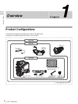
Page 6: ...shown in the figure below The operation of the basic camera unit is the same in all cases Microphone HXC D70K HXC D70L CBK VF01 Viewfinder Zoom Lens HXC D70 Camera Head HXC D70H Test Chart for Flange Focal Length Adjustment Cable Clamp Belt Fitting Shoe for DXF 8011 Hexagonal Wrench for DXF 8011 1 Only supplied with HXC D70H ...

Page 7: ...enables reproduction of natural skin tones under strong lighting Low key saturation Saturation in low key zones can be compensated Skin tone detail This function allows control emphasis or suppression of the detail level for just a certain hue or saturation area in the image such as skin tones Auto focus The 2 3 type auto focus lens supplied with HXC D70K ensures high quality shooting in all situa...

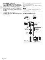
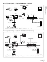
Page 8: ...ry Stick Duo slot which enables setup data storage and software upgrading using a Memory Stick Duo System Configuration Peripherals and related devices for the camera are shown in figures Note Production of some of the peripherals and related devices shown in the figures has been discontinued For advice on choosing devices please contact your Sony dealer or a Sony service representative Standalone...

Page 9: ...e Monitor Video Output HD SDI SD SDI VBS HDMI 1 An equivalent cable length of up to 100 m is approved For details refer to the operating instructions supplied with the HXCU D70 Camera Control Unit Microphone RCP D50 series Remote Control Panel HXC D70 CBK VF01 Viewfinder Zoom Lens for ENG EFP Return Video Input Memory Stick Duo VCT 14 U14 Tripod Adaptor Tripod for Portable Camera AC Power Multi co...

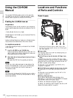
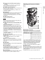
Page 10: ...Reader In such a case install the latest version you can download from the URL mentioned in Preparations above Note If you have lost or damaged the CD ROM you can purchase a new one to replace it Contact your Sony dealer or a Sony service representative Locations and Functions of Parts and Controls Power Supply a Power switch Turn the power supply on and off The indicator lights up in green when t...

Page 11: ... and Functions of Parts and Controls Chapter 1 Overview Note For your safety and to ensure proper operation of the camera Sony recommends the use of the following battery packs BP GL95A BP GL65A BP L60S and BP L80S ...

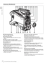
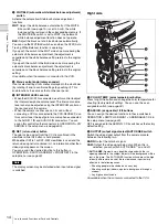
Page 12: ...t position of the viewfinder see page 24 h 1 4 inch screw type accessory shoe i Slide type accessory shoe j Viewfinder front to back positioning lever To adjust the viewfinder position in the front to back direction loosen this lever and the lock knob After adjustment retighten this lever and the lock knob k Viewfinder fitting shoe Attach a viewfinder For information on attaching the DXF 801 viewf...

Page 13: ...8V To supply phantom power 48 V to condenser microphones MIC When a microphone is connected LINE When a line level 0 dBu signal source is connected Select 48V when using the microphone supplied with HXC D70K D70L u Tripod mount When using the camera on a tripod attach the tripod adaptor optional see page 35 v Lens locking lever After inserting the lens in the lens mount rotate the lens mount ring ...

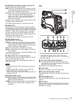
Page 14: ...hone connected to the AUDIO 1 IN and AUDIO 2 IN connectors You can assign this control to other connectors in OPERATION VR ASSIGN in the setup menu see page 59 f RET return video button The return video signal from the CCU is monitored in the viewfinder while this button is held pressed While either DXF 51 or DXF 20W viewfinder is used and the return video signal is monitored in it no information ...

Page 15: ... functions the same as the DISPLAY MENU switch on the rear operation panel g Memory Stick Duo slot and access lamp Take the cover off and insert a Memory Stick Duo into the slot The access lamp lights in green The lamp is lit in red while writing reading data to from the Memory Stick Duo Notes Only a Memory Stick of Duo size can be used with the camera When the access lamp is lit in red do not rem...

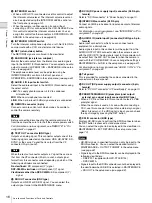
Page 16: ...C50WA viewfinder HD component Y signal Viewfinders other than DXF C50WA SD component Y signal m SDI OUT connector BNC type Outputs an HD SDI or SD SDI signal You can select the output signal format in the MAINTENANCE menu n DC IN DC power supply input connector XLR 4 pin female Refer to DC IN connector in Power Supply on page 10 o INTERCOM connector XLR 5 pin Connect an XLR 5 pin headset for input...

Page 17: ...this ring f Focus ring Turn this ring to adjust the focus This ring can be turned endlessly in both directions The faster you turn the faster the focusing mechanism operates to minimize the amount of turning required for focusing When you slide the focus ring back toward the camera the focus mode becomes Full MF mode see page 42 g Flange focal length adjustment button Press this to adjust the flan...

Page 18: ...ator flashes to indicate a warning f Eyepiece You can raise this up when required by the situation g Viewfinder barrel You can raise this up or rotate when required by the situation h PEAKING control Turning this control clockwise adjusts the picture sharpness and makes focusing easier This control has no effect on the output signals of the camera i CONTRAST control Adjust the contrast of the scre...

Page 19: ...when the internal electrical filter 5600K is set to ON l Filter indication Displays the type of ND filter currently selected with a number 1 2 3 or 4 m ECC indication Displays the type of electrical CC filter A to D currently selected n White balance memory indication Shows the currently selected white balance automatic adjustment memory This is not displayed when a CCU is connected W A The WHITE ...

Page 20: ...he IND function Display options can be set using the menu For details see OPERATION IND in the setup menu page 57 CALL TALLY indication in digital viewfinders Digital viewfinders have no tally lamps CALL TALLY indication is displayed as follows In digital viewfinders such as CBK VF01 E X Z 9 9 F 2 5 D E X 1 2 0 5 V CALL ...

Page 21: ...e cable When required secure the cable using the supplied cable clamp belt To use the cable clamp belt 1 Insert the belt bracket C into hole A or B of the cable clamp belt 2 1 Remove the screw hole cover on the top rear of the camera and 2 secure the cable clamp belt to the camera using the two supplied screws B3 10 3 1 Release the buckle 2 bundle the cable with the belt 3 then lock the buckle aga...

Page 22: ...pays ou la région où vous vous trouvez VORSICHT Explosionsgefahr bei Verwendung falscher Batterien Batterien nur durch den vom Hersteller empfohlenen oder einen gleichwertigen Typ ersetzen Wenn Sie die Batterie entsorgen müssen Sie die Gesetze der jeweiligen Region und des jeweiligen Landes befolgen Removing the Rear Cover Remove the rear cover before using AC power or attaching a battery pack to ...

Page 23: ... To attach the battery pack 1 Press the battery pack against the back of the camera aligning the line on the side of the battery pack with the matching line on the camera 2 Slide the battery pack down until its LOCK arrow points at the matching line on the camera Note If the battery pack is not attached correctly the terminal may be damaged To detach the battery pack Holding the release button in ...

Page 24: ...on the video or the tally indicator may not operate properly 1 1 Loosen the viewfinder left to right positioning ring 2 attach the viewfinder to the viewfinder fitting shoe and 3 tighten the viewfinder left to right positioning ring 2 Remove the cover of the viewfinder connector and couple it to the VF connector rectangular Detaching the viewfinder You can detach the viewfinder by following the at...

Page 25: ...der to B T Lifting Up the Viewfinder Barrel and Eyepiece You can view the LCD screen inside the viewfinder or its mirrored image by lifting up the viewfinder barrel or the eyepiece This section describes how to lift up the viewfinder barrel and detach it The eyepiece can also be lifted up and detached in the same way To raise up the viewfinder barrel 1 Push the clip on the bottom to release and 2 ...

Page 26: ...l of the viewfinder to L R you can reverse the picture and other information displayed in the viewfinder horizontally Adjusting the Viewfinder Focus and Screen To adjust the viewfinder focus Turn the diopter adjustment ring until the viewfinder image is sharpest To adjust the viewfinder screen Adjust the peaking contrast and brightness of the viewfinder screen with the controls shown below Peaking...

Page 27: ...the DXF 20W viewfinder To detach the viewfinder from the camera conduct the attachment procedure in reverse When removing the viewfinder from the camera pull up the stopper Attaching the DXF 801 viewfinder Replace the viewfinder fitting shoe following the steps below before attaching the DXF 801 viewfinder Note The following accessories are not supplied with the HXC D70K D70L A 3 5 type color LCD ...

Page 28: ...etach the DXF C50WA 51 viewfinder Loosen the fixing ring and pull the viewfinder out of the accessory shoe in the opposite direction Attaching a 5 type color LCD viewfinder A 5 type color LCD viewfinder can be panned over an angle of 30 to the right and 30 to the left To rotate the viewfinder for panning up to 90 in the left and right directions attach the optional accessory shoe kit service part ...

Page 29: ...ea of Use When using the camera for the first time The area of use is not factory preset Before using the camera you need to set this item You cannot use the camera without setting this item To set the area of use 1 Set the power switch to the ON The screen for setting the area of use appears in the viewfinder 2 Press the menu control knob The settings for selectable areas of use are displayed Con...

Page 30: ... the camera 2 While holding the menu control knob pressed set the DISPLAY MENU switch to MENU The camera enters menu mode and TOP is displayed at the upper right corner of the screen 3 Rotate the menu control knob to set the pointer to TOP and push on the menu control knob The TOP MENU screen is displayed 4 Rotate the menu control knob to position the pointer to MAINTENANCE and push on the menu co...

Page 31: ... and remove the lens mount cap from the lens mount 2 Align the center pin on the lens with the center slot in the lens mount and insert the lens into the mount 3 Holding the lens in place push the lens locking lever down to lock the lens Caution If the lens is not firmly locked it may come off while the camera is being used This could cause a serious accident Make sure the lens is firmly locked It...

Page 32: ...ect no object closer to the camera than the chart enters the screen at the wide angle end Carrying out the adjustment When using the auto focus lens With the lens supplied with the HXC D70K zoom and focus operations automatically adjust the flange focal length 1 Open the iris position the supplied flange focal length adjustment chart approximately three meters 10 ft away from the camera and arrang...

Page 33: ...ophone requiring a phantom power supply from the camera 48V 6 Switch the input level to match the sensitivity of the microphone used When the camera is used on its own switch the input level by changing the setting of either MAINTENANCE AUDIO factory default setting is 60 dB or OPERATION VR ASSIGN in the setup menu For details see page 67 or page 59 Notes If the input level on the camera is not at...

Page 34: ...h the viewfinder and tighten the ball joint lock lever 4 Connect the microphone cable to the AUDIO 2 IN connector 5 Follow step 5 and 6 in Connecting a Microphone to the AUDIO 1 IN Connector see page 33 Notes If the input level on the camera is not at an appropriate setting for the microphone sensitivity loud sounds may be distorted and the signal to noise ratio may be affected In order for the AU...

Page 35: ...s contact your Sony dealer or a Sony service representative Mounting the Camera to a Tripod Mount the camera to a tripod using an optional VCT U14 tripod adaptor Notes If camera instability still affects shooting when using a tripod with the VCT U14 tripod adaptor use the VCT 14 tripod adaptor for professional use Select an appropriate hole from among those at the bottom of the tripod adaptor cons...

Page 36: ...the red button and move the lever in the direction of the arrow to return the pin to its original position It is not possible to mount a camera with the pin not seated Using the Shoulder Strap Optional The optional shoulder strap service part number A 6772 374 C can be attached to the camera To attach the shoulder strap 1 Fit one of the clips to a shoulder strap fitting 2 Fit the other clip to the...

Page 37: ...ent helps you get the best balance for shooting with the camera on your shoulder 1 Raise the lever in the center of the shoulder pad to unlock the shoulder pad 2 Slide the shoulder pad backward or forward until it is in the most convenient position 3 Bring down the lever to lock the shoulder pad in the selected position Press here and pull in the direction shown by the arrow to release Shoulder pa...

Page 38: ...tings of switches control knobs Settings in the OPERATION menu page 56 and the PAINT menu page 61 Electronic shutter setting page 40 Settings for the output signals from the camera page 44 Flange focal length setting page 32 4 Adjust the eyepiece focus as well as the contrast and brightness of the viewfinder image For viewfinder settings refer to the operation manual for the viewfinder 5 If requir...

Page 39: ...refer to the maintenance manual 1 Set the OUTPUT AUTO KNEE switch to CAM 2 Push the WHT BLK switch to BLK and release the switch The message Executing appears during execution and changes to OK when the adjustment finishes Adjustment values are saved to memory automatically Notes During the black balance adjustment the iris is automatically closed During the black balance adjustment the gain selec...

Page 40: ...able switch This allows you to switch between color temperatures 3200K 4300K 5600K 6300K that have been assigned to up to four positions A to D with each press of the assignable switch 1 Select MAINTENANCE WHITE FILTER in the setup menu see page 69 2 Select the position to which to assign a CC filter by selecting one of ELECTRICAL CC A to ELECTRICAL CC D and then turn the menu control knob to sele...

Page 41: ...lowing range with respect to the standard value 0 25 to 1 increasing by increments of 0 25 About 0 25 to 1 stop further open 0 25 to 1 decreasing by increments of 0 25 About 0 25 to 1 stop further close Also you can set the area where light detection occurs To change the reference value 1 Set MAINTENANCE AUTO IRIS AUTO IRIS in the setup menu to ON see page 66 2 Change the reference value in MAINTE...

Page 42: ...absolute positions of the focus ring Peaking You can turn the PEAKING knob on the viewfinder to use the peaking function Edges are emphasized in the monitor picture which facilitates manual focusing The recorded video signals are not affected Adjusting in MF Mode When you slide the focus ring forward toward the lens hood and set the FOCUS switch to M manual the focus mode becomes MF mode in which ...

Page 43: ...function extracts the irregularities of a subject and converts the integrated values to a level indicator which shows the focus condition The focus setting where the indicator shows the maximum level is the best focus setting The range of the indicator substantially changes depending on picture elements or shooting environments Adjust it with GAIN and OFFSET as required 1 Set the DISPLAY MENU swit...

Page 44: ...t in the viewfinder With HD SDI you can obtain a signal that includes the same information as that being displayed in the viewfinder according to the settings for VF MARKER CHARACTER VF DETAIL ZEBRA etc The ON OFF or other settings for adding information are common to those for the viewfinder The output is synchronized with switching among Y R G and B or switching to a return signal To output as H...

Page 45: ...he lower half of the image differs considerably from the upper half Since the function may be inadvertently activated under certain shooting conditions in which the brightness between the upper and lower half of the image differs markedly be sure to use the function only for shooting footage exposed to flash light To reduce flash band artifacts If flash band artifacts are detected using this funct...

Page 46: ...IS GAIN SHUTT WHITE BATT RETURN TALK AUDIO MESSAG TALLY VF DISPLAY 2 FRONT REAR VR IND ND CC WHITE 5600K GAIN SHUTT EXT FORMAT VF MARKER MARKER CENTER SAFETY ZONE EFFECT ASPECT MASK SAFETY VF DETAIL VF DETAIL CRISP FREQUENCY FAT MODE AREA ZOOM LINK COLOR DETAIL PEAK COLOR CHROMA LEVEL FOCUS ASSIST INDICATOR MODE LEVEL GAIN OFFSET AREA MARKER SIZE POSITION POSITION H POSITION V ZEBRA ZEBRA ZEBRA1 L...

Page 47: ...TE CAM t MS PRESET FILE ID CAM CODE DATE LENS FILE FILE CENTER MARKER H POS V POS STORE SW STATUS FLARE GAMMA BLK GAM KNEE WHT CLIP DETAIL LVL DEP SKIN DTL MATRIX VIDEO LEVEL WHITE BLACK FLARE GAMMA V MOD FLARE V MOD D SHAD TEST COLOR TEMP WHITE AUTO WHITE BALANCE COLOR TEMP BALANCE ATW SPEED MASTER GAMMA LEVEL COARSE TABLE GAMMA TEST BLACK GAMMA LEVEL RANGE TEST SATURATION SATURATION LOW KEY SAT ...

Page 48: ... t MS FILE ID CAM CODE DATE AUTO SETUP AUTO BLACK AUTO WHITE AUTO LEVEL AUTO WHITE SHADING AUTO BLACK SHADING TEST WHITE SHADING V SAW V PARA H SAW H PARA WHITE AUTO WHITE SHADING WHITE SHAD MODE BLACK SHADING V SAW V PARA H SAW H PARA BLK SET BLACK MASTER GAIN AUTO BLACK SHADING AUTO IRIS AUTO IRIS WINDOW OVERRIDE IRIS LEVEL APL RATIO IRIS GAIN IRIS CLOSE CIS COMP FLICKER REDUCE MODE FREQ FLASH B...

Page 49: ...CAL CC D OTHERS 1 CAM BARS V DTL CREATION DTL H V MODE TEST2 MODE WHITE SETUP MODE ALAC AUTO FLANGE BACK HDSDI REMOTE I F OTHERS 2 DATE TYPE F NO DISP AF DETECT AREA EXT RETURN EXT RETURN SD ASPECT OPERATOR FILE READ MS t CAM WRITE CAM t MS PRESET STORE PRESET FILE FILE ID CAM MODE DATE SCENE FILE 1 2 3 4 5 STORE STANDARD READ MS t CAM WRITE CAM t MS FILE ID CAM CODE DATE REFERECNE STORE FILE STAN...

Page 50: ...n use the DISPLAY MENU switch either on the right side or the rear panel of the unit The menu control knob at the low on the front panel and that on the rear panel function the same Rotate the knob to select menu items or values and push on it to register enter the selection Right side BOARD STATUS OHB DPR SY IF PS PLD VERSION SY DPR1 DPR2 IF TX ROM VERSION AT SERIAL NO MODEL NO Menu control knob ...

Page 51: ... and deleting pages can be performed with the USER MENU CUSTOMIZE menu USER MENU CUSTOMIZE This menu allows you to edit the USER menu For details on the USER menu see Editing the USER Menu page 53 ALL This menu permits you to control all items of the OPERATION menu PAINT menu MAINTENANCE menu FILE menu and DIAGNOSIS menu as a single menu OPERATION This menu contains items for camera operators to o...

Page 52: ...enu page repeat steps 1 through 3 To specify a character string When you press the menu control knob with the pointer pointing to an item for which a character string such as a file ID is to be specified a cursor and the list of selectable characters are displayed The displayed cursor can be moved by rotating the menu control knob 1 Set the cursor to the position where you wish enter a character t...

Page 53: ... the menu control knob to move the pointer to any of USER 1 EDIT to USER 19 EDIT then push on the menu control knob to display the page If a different page is displayed turn the menu control knob until the desired page appears then push on the menu control knob to select the page Example When you select the USER 2 EDIT page 3 Move the pointer to the item to be added this operation is unnecessary i...

Page 54: ...erted above the specified item Note You cannot insert a blank line on a page where 10 items have already been registered Editing by pages You can add a page to the USER menu delete a page from the USER menu or replace pages using the EDIT PAGE of the USER MENU CUSTOMIZE menu To add a page 1 Select USER MENU CUSTOMIZE on the TOP MENU screen If this is the first time the USER MENU CUSTOMIZE menu has...

Page 55: ...nu control knob to move the pointer to the page that you wish to move The EDIT FUNCTION screen appears 2 Select MOVE then push on the menu control knob The EDIT PAGE screen appears again 3 Move the pointer to the position where you wish to move the page then push on the menu control knob The page selected in step 1 is moved to the position selected in step 3 In the above example SWITCH ASSIGN1 mov...

Page 56: ...ND filter indication in the viewfinder CC ON OFF Displays or hides the CC filter indication in the viewfinder 5600K ON OFF Displays or hides the 5600K mode indication in the viewfinder IRIS ON OFF Displays or hides the F value iris opening indication in the viewfinder GAIN ON OFF Displays or hides the gain value indication in the viewfinder SHUTT ON OFF Displays or hides the shutter ECS indication...

Page 57: ... or hides the center marker in the viewfinder 1 2 3 4 Selects the center marker type 1 Entire cross 2 Entire cross with a hole 3 Center 4 Center with a hole SAFETY ZONE ON OFF Displays or hides the safety zone in the viewfinder 80 0 90 0 92 5 95 0 Selects the safety zone size EFFECT ON OFF FOCUS Displays or hides the effective pixel area in the viewfinder FOCUS Displayed when INDICATOR in FOCUS AS...

Page 58: ...s or hides the detection area of the focus as a marker in the viewfinder ASPECT Displayed when ASPECT SAFETY of VF MARKER is ON SIZE SMALL MIDDLE LARGE Changes the detection range If larger range than needed is selected both the subject and background are detected This may prevent the indicator to function properly POSITION LEFT CENTER RIGHT Roughly sets the position of the detection area POSITION...

Page 59: ...NTERCOM Assigns a function to the VTR button on the mounted lens FRONT RET2 OFF VTR S S RETURN1 SW RETURN2 SW INTERCOM Assigns a function to the RET button on the camera VR ASSIGN 12 FRONT VR AUDIO1 AUDIO2 AUDIO1 2 INTERCOM EARPHONE OFF INTERCOM Assigns a function to the INTERCOM LEVEL control on the front panel INTERCOM Not available when HXCU D70 is connected REAR VR AUDIO1 AUDIO2 AUDIO1 2 INTER...

Page 60: ...cute by ENTER PRESET Loads the preset data Execute by ENTER FILE ID Enters an operator file name using up to 16 characters to be written to a Memory Stick Duo See To specify a character string on page 52 CAM CODE Displays the camera code Display only DATE Displays the date Display only LENS FILE 17 U11 FILE 1 to 17 Displays the selected file number 1 to 16 When using a non serial lens 17 When usin...

Page 61: ...e balance BLACK R G B M 99 to 99 0 Sets the black level value FLARE R G B M 99 to 99 0 Sets the flare compensation level GAMMA R G B M 99 to 99 0 Sets the gamma level V MOD R G B M 99 to 99 0 Sets the V modulation level FLARE ON OFF Sets the flare compensation function to on or off V MOD ON OFF Sets the V modulation shading compensation function to on or off D SHAD ON OFF Sets the dynamic shading ...

Page 62: ...EST OFF SAW 3STEP 10STEP Selects the test signal displayed on the monitor screen SATURATION P06 SATURATION 99 to 99 0 Sets the saturation level ON OFF Sets the saturation function to on or off LOW KEY SAT 99 to 99 0 Sets the low key saturation level RANGE LOW L MID H MID HIGH Selects the saturation range in which the low key saturation function is activated ON OFF Sets the low key saturation funct...

Page 63: ...ASE 0 to 359 0 Adjusts the phase of the color signal controlled by the skin tone detail function WIDTH 0 to 90 29 Adjusts the width of the color signal controlled by the skin tone detail function SAT 99 to 99 89 Sets the color saturation level color intensity controlled by the skin tone detail function LEVEL 99 to 99 0 Sets the skin tone detail level ABS Displays the inverted values as absolute va...

Page 64: ... according to the individual settings PRESET ON OFF Sets the preset matrix function to on or off SMPTE 240M ITU 709 SMPTE WIDE NTSC EBU ITU 601 Selects the preset matrix When MATRIX is set to OFF cannot be changed USER ON OFF Sets the user matrix function to on or off When MATRIX is set to OFF cannot be changed MULTI ON OFF Sets the multi matrix function to on or off The PHASE HUE and SAT settings...

Page 65: ...ute by ENTER Adjusts the auto black and auto white functions when RCP D50 is connected AUTO WHITE SHADING Activates the auto white shading compensation function Execute by ENTER AUTO BLACK SHADING Activates the auto black shading compensation function Execute by ENTER TEST OFF SAW 3STEP 10STEP Sets the display format of test signal WHITE SHADING M02 V SAW R G B 99 to 99 0 Sets the SAW white shadin...

Page 66: ...N 3 0 3 6 9 12dB Sets the master gain value AUTO BLACK SHADING Performs the auto black shading compensation Execute by ENTER AUTO IRIS M04 AUTO IRIS ON OFF Activates the auto iris function WINDOW 1 2 3 4 5 6 Selects the auto iris window The shaded parts indicate the area where light detection occurs OVERRIDE 99 to 99 Sets the override to temporarily change the reference value for brightness of the...

Page 67: ...tivated AUDIO M06 U14 MIC GAIN AUDIO1 20dB 30dB 40dB 50dB 60dB Sets the input gain of the AUDIO 1 IN connector for an external microphone Settings in When HXCU D70 is connected cannot be changed AUDIO2 20dB 30dB 40dB 50dB 60dB Sets the input gain of the AUDIO 2 IN connector for an external microphone Settings in When HXCU D70 is connected cannot be changed CCZ OUT Adjusts the microphone output set...

Page 68: ... for SD signal Outputs a down converted HD BARS signal when DISABLE is selected SD CCS ON OFF Sets the cross color suppression function to on or off 99 to 99 0 Sets the cross color suppression level SD DETAIL ON OFF Sets the detail adjustment function for down converted output to on or off 99 to 99 0 Sets the SD detail signal level CRISP 99 to 99 0 Sets the crispening level LVL DEP 99 to 99 0 Sets...

Page 69: ...y only GENLOCK DISABLE ENABLE Activates or deactivates the genlock function STATUS Indicates the signal format input to the GENLOCK connecter Display only FORMAT V PHASE 1024 to 1023 0 Adjusts the vertical phase for GENLOCK H PHASE 1700 to 1700 0 Adjusts the horizontal phase for GENLOCK H FINE 99 to 99 0 Finely adjusts the horizontal phase for GENLOCK Available only for SD output SC PHASE 0 to 359...

Page 70: ...DSDI REMOTE I F OFF R TLY Selects whether to activate the recording control function for an external device connected to the SDI OUT connector Available when MAIN is selected in MAINTENANCE SDI OUT OUTPUT in the setup menu OTHERS 2 M19 DATE TYPE 1 Y Mn D 2 Mn D 3 D M Y 4 D M 5 M D Y 6 M D Selects the date display format Y Year Mn Month numeric M Month character string D Day F NO DISP CONTROL RETUR...

Page 71: ...preset data on the OPERATION menu in the camera s internal memory Execute by ENTER FILE ID Enters an operator file name using up to 16 characters to be written to a Memory Stick Duo See To specify a character string on page 52 CAM CODE Displays the camera code Display only DATE Displays the date Display only SCENE FILE F02 1 File number and file ID Stores and reads scene files paint data 2 3 4 5 S...

Page 72: ... 16 characters to be written to a Memory Stick Duo See To specify a character string on page 52 CAM CODE Displays the camera code Display only DATE Displays the date Display only LENS FILE F04 STORE FILE Stores the current settings in the lens file to the camera s internal memory Execute by ENTER No 1 to 17 1 to 16 When using a non serial lens 17 When using a serial lens NAME Lens file name Change...

Page 73: ... Stick Duo Execute by ENTER Note Clears all the data stored in a Memory Stick Duo DIAGNOSIS Page title Page No Item Settings Description BOARD STATUS D01 OHB OK NG Displays the OHB Block status DPR OK NG Displays the DPR board status SY OK NG Displays the SY board status IF OK NG Displays the IF board status PS OK NG Displays the PS board status PLD VERSION D02 SY Displays the PLD version for SY b...

Page 74: ...te Never use organic solvents such as thinners Note about the Battery Terminal The battery terminal of this unit the connector for battery packs and AC adaptors is a consumable part Power may not be supplied to the unit properly if the pins of the battery terminal are bent or deformed by shock or vibrations or if they become corroded due to prolonged outdoor use Periodic inspections are recommende...

Page 75: ...onsult Sony service personnel VF RPN BUSY RPN compensation was attempted from an external device while being operated using the camera menu Consult Sony service personnel NO MEMORY STICK A Memory Stick Duo operation was attempted with no Memory Stick Duo in the slot MEMORY STICK ERROR An error occurred during access to a Memory Stick Duo FORMAT ERROR A Memory Stick Duo operation was attempted with...

Page 76: ...vice representative Use and storage locations Store in a level ventilated place Avoid using or storing the camera in the following places In excessive heat or cold operating temperature range 0 C to 40 C 32 F to 104 F Remember that in summer in warm climates the temperature inside a car with the windows closed can easily exceed 50 C 122 F In damp or dusty locations Locations where the camera may b...

Page 77: ...ou activate the Flicker Reduction function In such cases use the electronic shutter Focal plane Owing to the characteristics of the pickup elements CMOS image sensors for reading video signals subjects that quickly move across the screen may appear slightly skewed Flash band The luminance at the top and bottom of the screen may change when shooting a flashlight beam or a light source that quickly ...

Page 78: ...op the Memory Stick Duo Do not disassemble or modify the Memory Stick Duo Do not allow the Memory Stick Duo to get wet Do not use or store the Memory Stick Duo in a location that is Extremely hot such as in a car parked in the sun Under direct sunlight Very humid or subject to corrosive substances To prevent data loss make backups of data frequently In no event will Sony be liable for any loss of ...

Page 79: ... IN 0 dBu balanced INTERCOM XLR type 5 pin female 1 EARPHONE Stereo minijack 1 DC IN XLR type 4 pin 1 10 5 to 17 0 V DC DC OUT 4 pin 1 10 5 to 17 0 V DC maximum rated current 1 5 A The numerical value may vary depending on usage conditions SDI IN BNC type 1 SDI OUT BNC type 1 TEST OUT BNC type 1 PROMPTER GENLOCK BNC type 1 1 0 Vp p 75 Ω LENS 12 pin 1 supplying power to the lens 10 5 to 17 0 V DC m...

Page 80: ...855S UHF synthesized diversity tuner WRR 860A 861 862 Digital Wireless Receiver DWR S01D Other peripheral devices Tripod adaptor VCT 14 U14 Shoulder strap Part No A 6772 374 C Low repulsion shoulder pad Part No A 8286 346 A Accessory shoe kit Part No A 8274 968 B WRR mount bracket Part No A 8278 057 B Memory Stick Duo Equipment for maintenance and easier handling Soft carrying case LC DS300SFT Mai...

Page 81: ...8 dBu VR Max 250 Ω Load 5 1 9 6 EXT VIEW 1 2 3 4 5 EXT VIEW No Signal Specifications 1 TX OUT x for RCP SERIAL DATA OUT 2 TX OUT Y for RCP 3 RX IN x for RCP SERIAL DATA IN 4 RX IN Y for RCP 5 TX GND GND for TX 6 UNREG OUT 10 5 to 17 V dc 200 mA max 7 UNREG GND GND for UNREG OUT 8 RCP PIX OUT 75 Ω 1 0 Vp p SD Video CHASSIS GND CHASSIS GND No Signal Specifications 1 UNREG GND GND for UNREG OUT 2 NC ...

Page 82: ...82 Pin assignment Appendix AUDIO 1 2 IN No Signal Specifications 1 AUDIO 1 2 G 60 50 40 30 20 dBu LINE 0 dBu Selectable Balanced 2 AUDIO 1 2 IN X 3 AUDIO 1 2 IN Y EXT VIEW 1 3 2 ...

Page 83: ......

Reviews: