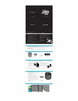
background image

– 1 –

SERVICE MANUAL

AEP Model

ICF-703/703L

UK Model

ICF-703L

ICF-703/703L

FM/AM RADIO

ICF-703

FM/MW/LW 3 BAND RADIO

ICF-703L

(Photo: ICF-703L (BLACK))

SPECIFICATIONS

Frequency range:

Italy

Band

ICF-703

ICF-703L

FM

87.5 - 108.0 MHz

          —

AM

526.5 - 1606.5 kHz

          —

Other countries

Band

ICF-703

ICF-703L

FM

87.5 - 108.0 MHz

87.5 - 108.0 MHz

SW

           —

         —

AM (MW)

530 - 1605 kHz

530 - 1605 kHz

LW

           —

153 - 255 kHz

Speaker

Approx. 10.2 cm (4 

1/8

 inches) dia. 8 ohms

Power output

430 mW (at 10 % harmonic distortion)

Output

v

 jack (ø 3.5 mm minijack)

Power requirements

With the supplied AC power cord:

220 - 230 V AC, 50 Hz

With four R6 (size AA) batteries: 6V DC

Dimensions

Approx. 265 

×

 137 

×

 69 mm (w/h/d)

(10 

1/2


×

 5 

1/2


×

 2 

3/4

 inches) incl. projecting parts

and control with carrying handle pushed in.

Mass

Approx. 1019 g (2 lb 4 oz) incl. batteries

Supplied accessory

AC power cord (1)

Design and specifications are subject to change without
notice.

Ver 1.0  2000. 03

Summary of Contents for ICF-703

Page 1: ...605 kHz LW 153 255 kHz Speaker Approx 10 2 cm 4 1 8 inches dia 8 ohms Power output 430 mW at 10 harmonic distortion Output v jack ø 3 5 mm minijack Power requirements With the supplied AC power cord 220 230 V AC 50 Hz With four R6 size AA batteries 6V DC Dimensions Approx 265 137 69 mm w h d 10 1 2 5 1 2 2 3 4 inches incl projecting parts and control with carrying handle pushed in Mass Approx 1019...

Page 2: ...together since it s supply two pieces in one package as a spare parts mark mark white white only CF2 CF3 CF4 mark mark CF3 CF2 CF4 Notes on Chip Component Replacement Never reuse a disconnected chip component Notice that the minus side of a tantalum capacitor may be damaged by heat SAFETY RELATED COMPONENT WARNING COMPONENTS IDENTIFIED BY MARK 0 OR DOTTED LINE WITH MARK 0 ON THE SCHEMATIC DIAGRAMS...

Page 3: ...e occurs wipe the battery compartment with a soft cloth before inserting new ones House Current See Fig B 1 Connect the AC power cord supplied to the AC IN jack of the radio 2 Plug into a wall outlet Operating the Radio 1 Press OPERATION to turn on the radio 2 Select a desired band and tune in a station using TUNING TUNE tuning indicator lights up when a station is tuned in 3 Adjust the volume usi...

Page 4: ... in the numerical order given 2 1 CABINET REAR 2 2 POWER BOARD SECTION 2 DISASSEMBLY 1 lid battery case 2 BTP 3x16 3 BTP 3x16 4 BTP 3x16 5 cabinet rear 1 BTP 3x10 5 button power 4 Removal the solders CN401 BLU BLK PNK 6 POWER board 3 CN401 2 ...

Page 5: ...TP 3x10 7 claws qa MAIN board 5 BTP 2 6x5 6 LED board 2 knob band 3 chassis 0 4 Removal the solder 1 rack pointer rack pointer 2 pointer Setting the Pointer A 1 Turn the Knob Tuning in the direction of A until it is stopped 2 Place the rack as shown in the figure 3 Mount the pointer ...

Page 6: ...NT Adjust for a maximum reading on level meter L6 L7 86 5 MHz CT1 4 109 5 MHz SECTION 3 ELECTRICAL ADJUSTMENTS FM SECTION BAND switch FM telescopic antenna terminal 0 01µF FM RF signal generator 400Hz 30 FM modulation frequency deviation 22 5kHz Output level as low as possible set 16Ω set earphone jack EPJ1 level meter Repeat the procedures in each adjustment several times and the frequency covera...

Page 7: ...W TRACKING ADJUSTMENT Adjust for a maximum reading on level meter L1 2 160 kHz CT5 240 kHz Adjustment Location MAIN BOARD ICF 703L LW SECTION BAND switch LW CT5 LW TRACKING 703L ADJUSTMENT CT1 2 AM 703 MW 703L FREQUENCY COVERAGE ADJUSTMENT L4 FM FREQUENCY COVERAGE ADJUSTMENT CT1 1 AM 703 MW 703L TRACKING ADJUSTMENT L6 7 FM TRACKING ADJUSTMENT T1 AM 703 MW 703L IF ADJUSTMENT CT1 4 FM TRACKING ADJUS...

Page 8: ...01 JW401 S401 CN401 1 677 379 1 677 381 11 1 677 380 11 11 1 5 1 3 CT5 CT6 CV1 TUNING ANT1 FM TELESCOPIC ANTENNA C31 1 15 1 3 16 30 PNK BLU L7 CT1 4 CT1 3 CT1 2 CT1 1 3 4 1 2 ACJ1 AC IN EPJ1 v S401 OPERATION ON STANDBY DRY BATTERY SIZE D IEC DESIGNATION R20 3PCS 4 5V C402 SP1 SPEAKER BLU PNK D301 TUNE BLU PNK GRN CLEAR BLU BLK RED RED GRN BLU BLK RED CLEAR BLU L1 FERRITE ROD ANTENNA L1 2 LW 703L 7...

Page 9: ...Total current is measured with power on Power voltage is dc 4 5V and fed with regulated dc power supply from battery terminal Voltage is dc with respect to ground under no signal detuned condition no mark FM AM or LW Voltages are taken with a VOM Input impedance 10 MΩ Voltage variations may be noted due to normal produc tion tolerances Signal path F FM Abbreviation IT Italian model Note The compon...

Page 10: ...ASSY 703L 19 A 3683 177 A MAIN PC BOARD ASSY 703 AEP 19 A 3683 196 A MAIN PC BOARD ASSY 703 IT 20 3 043 346 01 HOLDER FERRITE ROD ANTENNA 21 3 043 342 01 DRUM A VC 22 3 364 941 11 SCREW B 2 6X5 NYLOK 23 3 043 338 01 KNOB TUNING BLACK 23 3 043 338 11 KNOB TUNING WHITE AEP 24 3 045 680 01 SPRING TUNING 25 3 043 336 01 SHAFT TUNING 26 7 671 112 11 BALL STEEL 27 7 685 534 14 SCREW BTP 2 6X8 TYPE2 N S ...

Page 11: ... 50V C21 1 124 234 00 ELECT 22uF 20 16V C22 1 126 925 11 ELECT 470uF 20 00 10V C23 1 164 004 11 CERAMIC CHIP 0 1uF 10 25V C24 1 109 982 11 CERAMIC CHIP 1uF 10 00 10V C25 1 163 009 11 CERAMIC CHIP 0 001uF 10 50V C31 1 102 998 11 CERAMIC 5PF 0 50PF 50V EXCEPT 703 IT C31 1 102 942 00 CERAMIC CHIP 5PF 0 50PF 50V 703 IT C37 1 163 088 00 CERAMIC CHIP 5PF 50V FILTER CF1 1 578 677 11 FILTER CRYSTAL CF2 1 ...

Page 12: ...P 100K 5 1 10W 703 VARIABLE RESISTOR RV1 1 225 498 11 RES VAR CARBON 50K VOL RV2 1 225 499 11 RES VAR CARBON 10K TONE SWITCH S1 1 552 574 21 SWITCH SLIDE BAND 703L S2 1 552 370 00 SWITCH SLIDE BAND 703 TRANSFORMER T1 1 404 790 11 TRANSFORMER IF 1 677 381 11 POWER BOARD INLET 0ACJ1 1 526 838 11 INLET AC 2P AC IN CAPACITOR C401 1 164 004 11 CERAMIC CHIP 0 1uF 10 25V C402 1 126 927 11 ELECT 2200uF 20...

Reviews: