background image

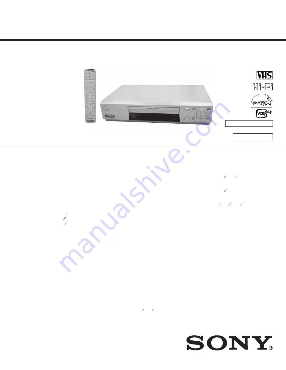
SLV-N55/N77/N88/N99

RMT-V307/V402/V402A/V402B

US Model

Canadian Model

SERVICE MANUAL

VIDEO CASSETTE RECORDER

SPECIFICATIONS

6\VWHP

)RUPDW

9+6176&VWDQGDUG

9LGHRUHFRUGLQJV\VWHP

5RWDU\KHDGKHOLFDOVFDQQLQJ)0V\VWHP

9LGHRKHDGV

'RXEOHD]LPXWKIRXUKHDGV

9LGHRVLJQDO

176&FRORU(,$VWDQGDUGV

7DSHVSHHG

63PPV

LQFKHVV

(3PPV

LQFKHVV

/3PPV

LQFKHVV

SOD\EDFNRQO\

0D[LPXPUHFRUGLQJSOD\EDFNWLPH

KUVLQ(3PRGHZLWK7WDSH

5HZLQGWLPH

$SSUR[PLQZLWK7WDSH

7XQHUVHFWLRQ

&KDQQHOFRYHUDJH

9+)WR
8+)WR
&$79$WR$$WR::WR:

$QWHQQD

RKPDQWHQQDWHUPL)8+)

,QSXWVDQGRXWSXWV

/,1(,1DQG/,1(,1

9,'(2,1SKRQRMDFNHDFK
,QSXWVLJQDO9SSRKPVXQEDODQFHGV\QF

QHJDWLYH
$8',2,1SKRQRMDFNVHDFK
,QSXWOHYHOP9UPV
,QSXWLPSHGDQFHPRUHWKDQNLORKPV


/,1(287

9,'(2287SKRQRMDFN
2XWSXWVLJQDO9SSRKPVXQEDODQFHGV\QF

QHJDWLYH
$8',2287SKRQRMDFNV
6WDQGDUGRXWSXWP9UPV
/RDGLPSHGDQFHNLORKPV
2XWSXWLPSHGDQFHOHVVWKDQNLORKPV

7LPHUVHFWLRQ

&ORFN

4XDUW]ORFNHG

7LPHULQGLFDWLRQ

KRXUF\FOH

7LPHUVHWWLQJ

SURJUDPVPD[

*HQHUDO

3RZHUUHTXLUHPHQWV

9$&+]

Photo : SLV-N88

RMT-V402B

TS-10 MECHANISM

(SLV-N55/N77/N88)

SL MECHANISM

(SLV-N99)

2SHUDWLQJWHPSHUDWXUH

ƒ&WRƒ&ƒ)WRƒ)

6WRUDJHWHPSHUDWXUH

±ƒ&WRƒ&±ƒ)WRƒ)

Power consumption

22 W (SLV-N99)

18 W (SLV-N55/N77/N88)

6/91
$SSUR[îîPP
$SSUR[î î LQFKHV
6/91
$SSUR[îîPP
$SSUR[î îLQFKHV
6/91
$SSUR[îîPP
$SSUR[ î î LQFKHV

0DVV


6/916/91
$SSUR[NJ$SSUR[OER]
6/91
$SSUR[NJ$SSUR[OER]

6XSSOLHGDFFHVVRULHV

5HPRWHFRPPDQGHU
6L]H$$5EDWWHULHV
RKPFRD[LDOFDEOHZLWK)W\SHFRQQHFWRUV

'HVLJQDQGVSHFLILFDWLRQVDUHVXEMHFWWRFKDQJHZLWKRXW

QRWLFH

(

1(5*<

6

7$5

Š

LVD86UHJLVWHUHGPDUN

$VDQ

(

1(5*<

6

7$5

Š

3DUWQHU6RQ\&RUSRUDWLRQKDV

GHWHUPLQHGWKDWWKLVSURGXFWPHHWVWKH

(

1(5*<

6

7$5

Š

JXLGHOLQHVIRUHQHUJ\HIILFLHQF\

SLV-N99

Approx. 4.1 kg (Approx. 9 lb 6 oz)

'LPHQVLRQVLQFOXGLQJSURMHFWLQJSDUWVDQGFRQWUROV

ZKG

SLV-N99

Approx. 430 

×

 97 

×

 293 mm

(Approx. 17 

×

 3 

7


8


×

 11 

1


2

 inches)

Summary of Contents for RMT-V307

Page 1: ...V 6WDQGDUG RXWSXW P9UPV RDG LPSHGDQFH NLORKPV 2XWSXW LPSHGDQFH OHVV WKDQ NLORKPV 7LPHU VHFWLRQ ORFN 4XDUW ORFNHG 7LPHU LQGLFDWLRQ KRXU F FOH 7LPHU VHWWLQJ SURJUDPV PD HQHUDO 3RZHU UHTXLUHPHQWV 9 Photo SLV N88 RMT V402B TS 10 MECHANISM SLV N55 N77 N88 SL MECHANISM SLV N99 2SHUDWLQJ WHPSHUDWXUH WR WR 6WRUDJH WHPSHUDWXUH WR WR Power consumption 22 W SLV N99 18 W SLV N55 N77 N88 6 9 1 SSUR î î PP SSUR...

Page 2: ...e Department For Canadian model Manufacturing Technology Centre repairs this model We only supply the Parts that are listed in the Service Manual If you need any extra repair please call Sony at 1 877 602 2008 to tell them that you d like to send your unit to Manufacturing Technology Centre Manufacturing Technology Centre MTC 40 Sunray Street Whitby Ontario Canada L1N 8Y3 Attn Manufacturing Techno...

Page 3: ...VHS MECHANICAL ADJUSTMENT MANUAL VII MECHANISMDECK TS 10 MECHANISM Please use this manual with the service manual ...

Page 4: ...utch Ass y Removal 13 1 2 16 Lever Up Down Ass y Gear Center Ass y Removal 13 1 2 18 Lever Unit Pinch Ass y Plate Joint Spring Pinch Drive Removal 14 1 2 17 Guide Cassette Door Removal 14 1 2 19 Lever 9 Guide Ass y Removal 15 1 2 20 FE Head Removal 15 1 2 21 ACE Head Removal 16 1 2 22 Slider S T Ass y Removal 16 1 2 23 Plate Ground Deck Cylinder Ass y Removal 17 1 2 24 Belt Pulley Removal 17 1 2 2...

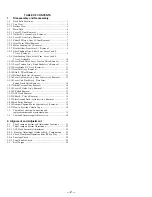
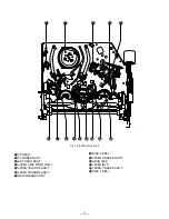
Page 5: ... Fig 1 1 Top parts Location 1 Œ GEAR FL CAM MOTOR LOADING ASS Y ˇ LEVER FL ARM ASS Y HOLDER FL CASSETTE ASS Y ˆ LEVER FL DOOR Ø SLIDER FL DRIVE 1 Disassembly and Reassembly 1 1 Deck Parts Locations 1 1 1 Top View ...

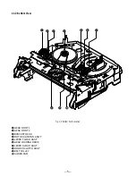
Page 6: ...arts Location 2 Œ FE HEAD CYLINDER ASS Y ˇ ACE HEAD ASS Y LEVER UNIT PINCH ASS Y ˆ LEVER 9 GUIDE ASS Y Ø LEVER TENSION ASS Y BAND BRAKE ASS Y DISK S REEL LEVER S BRAKE ASS Y GEAR IDLE Ô LEVER IDLE LEVER T BRAKE ASS Y Ò DISK T REEL ...

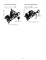
Page 7: ...tom View Œ ˇ ˆ Ø Fig 1 3 Bottom Parts Location Œ GEAR JOINT 1 GEAR JOINT 2 ˇ BRACKET GEAR MOTOR CAPSTAN ASS Y ˆ LEVER T LOAD ASS Y Ø GEAR LOADING DRIVE LEVER S LOAD ASS Y HOLDER CLUTCH ASS Y BELT PULLEY SLIDER CAM ...

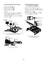
Page 8: ...der FL Cassette Ass y Œ and Lever FL Cassette R in the same time to release hooking from Main Base until the Boss A of Holder FL Cassette Ass y Œ is taken out from the Rail B 3 Lift the Holder FL Cassette Ass y Œ in this time you have to grasp the Lever FL Cassette R Continuously until the Holder FL Cassette Ass y Œ is taken out completely Note Be sure to insert Lever FL Cassette R in the directio...

Page 9: ... FL Cam Removal 1 Pull the Slider FL Drive Œ to the front direction 2 Remove the Slider FL Drive Œ in the direction of arrow Refer to Fig 1 6 3 Remove the Gear FL cam Note When reinstalling be sure to reassemble Slider FL drive Œ after you insert the Boss of Lever FL ARM R in Groove of Slider Fl drive Œ Assembly Align the Gear FL Cam Œ with the Gear worm wheel Post as shown drawing Refer to Timing...

Page 10: ... 1 Remove the Gear Worm wheel Œ Œ GEAR WORM WHEEL Fig 1 9 Gear Worm Wheel Removal 1 2 6 Motor Loading Ass y Removal 1 Remove the screw Œ 2 Remove the Motor Loading Ass y MOTOR LOADING ASS Y Œ SCREW Fig 1 10 Motor Loading Ass y Removal ...

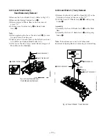
Page 11: ...ding Drive Slider Cam Lever Load S T Ass y Removal 1 Remove the Belt Pulley Refer to Fig 1 30 2 Remove the Gear Loading Drive Œ after releasing Hook A in the direction arrow as shown in detail drawing 3 Remove the Slider Cam 4 Remove the Lever Load S ˇ Link Load S ˆ Lever Load T Link Load T Ø Œ GEAR LOADING DRIVE ˆ LINK LOAD S ˇ LEVER LOAD S LEVER LOAD T Ø LINK LOAD T SLIDE CAM HOOK A Fig 1 11 Bra...

Page 12: ... Refer to Timing Point 2 4 Aline dot of Gear Loading drive with mark of Slider Cam ˇ as shown in drawing Refer to Timing Point 3 LEVER LOAD S Œ LEVER LOAD T LEVER LOAD S LEVER LOAD T PIN A PIN C PIN B PIN D ˇ SLIDER CAM TIMING POINT 2 TIMING POINT 1 TIMING POINT 3 1 2 10 Lever Pinch Drive Lever Tension Drive Removal 1 Remove the Lever Pinch Drive Œ Lever Tension Drive Œ LEVER PINCH DRIVE LEVER TEN...

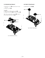
Page 13: ...topper of Main Base to the Mark B Œ SPRING TENTION LEVER STOPPER MARK B A LEVER TENTION ASS Y ˇ BAND BRAKE ASS Y 1 2 12 Lever Brake S T Ass y Removal 1 Release the Hook A and the Hook B C in the direction of arrow as shown in Fig 1 17 2 Lift the Lever S T Brake Ass y Œ with spring brake ˇ Assembly 1 Assembly the Lever S Brake Ass y Œ on the Main Base 2 Assembly the Lever T Brake Ass y with spring ...

Page 14: ...w A B 2 Lift the Lever Idle Œ Assembly 1 Apply oil in two Bosses of Lever Idle Œ 2 Assemble the Gear Idle with the Lever Idle Œ Note When replacing the Gear Idle be sure to add oil in the boss of Lever Idle Œ 1 2 14 Disk S T Reel Removal 1 Lift the Disk S T Reel Œ GEAR IDLE GEAR IDLE Œ LEVER IDLE A HOOK C B Fig 1 18 Gear Idle Ass y Removal ...

Page 15: ...ow as shown Fig 1 21 and lift the Lever Up Down Ass y Œ 2 Lift the Gear Center Ass y Assembly 1 Insert the Lever Up Down Ass y Œ in the rectan gular holes on Main Base as shown in Fig 1 22 2 Lift the Lever Up Down Ass y Œ about 35 degree Refer to Fig 1 22 3 Insert Ring of the Gear Center Ass y in the Guide of the Lever Up Down Ass y Œ 4 Insert the Gear Center Ass y in the post on Main Base 5 Push ...

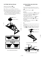
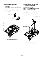
Page 16: ...uch the grease on the Roller Pinch 2 When reinstalling be sure to apply grease on the post pinch roller ˇ SPRING PINCH DRIVE Œ LEVER UNIT PINCH ASS Y PLATE JOINT Fig 1 23 Guide Cassette Door Removal Fig 1 24 Lever Unit Pinch Ass y Plate Joint Spring Pinch Drive Removal 1 2 17 Guide Cassette Door Removal 1 Lift the Hook A 2 Rotate the Guide Cassette Door Œ in the direction of arrow Note After reins...

Page 17: ...ote 1 Take extreme care not to get grease on the tape Guide Post 2 After reinstalling check the bottom side of the Post 9 Guide to the top side of Main Base Œ SPRING 9 GUIDE LEVER 9 GUIDE ASS Y A B Fig 1 25 Lever 9 Guide Ass y Removal 1 2 20 FE Head Removal 1 Remove the screw Œ 2 Lift the FE Head Œ FE HEAD Fig 1 26 FE Head Removal ...

Page 18: ...s y 2 Remove the screw Œ 3 Lift the ACE Head Ass y Œ SCREW HEAD ACE ASS Y 1 2 22 Slider S T Ass y Removal 1 Move the Slider S T Ass y Œ to slot and then lift it to remove Refer to arrow Œ SLIDER S ASS Y SLIDER T ASS Y Fig 1 27 ACE Head Removal Fig 1 28 Slider S T Ass y Removal ...

Page 19: ... not to touch the Cylinder Ass y ˇ and the tape guide post at reinstalling 2 When reinstalling Don t push down too much on Screw Driver Œ 3 SCREWS PLATE GROUND DECK ˇ CYLINDER ASS Y Fig 1 29 Plate Ground Deck Cylinder Ass y Removal 1 2 24 Belt Pulley Removal 1 Remove the Belt Pulley Œ Note Take extreme care not to get grease on Belt Pulley Œ at assembling or reassembling Œ BELT PULLEY Fig 1 30 Bel...

Page 20: ...CAPSTAN ASS Y 1 2 27 How to Eject the Cassette Tape If the unit does not operate on condition that is inserted into housing ass y 1 Turn the Gear worm Œ clockwise with screw driver Refer to arrow Other method Remove the Screw of Motor Load Ass y Separate the Motor Load Ass y Œ GEAR WORM Fig 1 32 Damper Capstan Motor Capstan Ass y Removal Fig 1 33 2 When Slider S T are approched in the position of ...

Page 21: ...SHAFT 9 GUIDE POST 3 GUIDE POST GUIDE ROLLER S T O O O O O O O CYLINDER ASS Y O O O O O O O O O FE HEAD O O O O O O O ACE HEAD O O O O O O O O O PINCH ROLLER O O O O O O O O O POST REEL S T SLEEVE TENSION POST CENTER LEVER IDLE BOSS 2Point CAPSTAN MOTOR PULLEY O O O O O BELT PULLEY O O O O O O O HOLDER CLUTCH ASS Y O O O O O O O O O GEAR CENTER ASS Y O O O O O O O O O GEAR IDLE 2Point O O O O O O ...

Page 22: ...Diamond Oil NT 68 Part No J 6090 072 A J 6082 012 A 8 192 605 41 8 192 605 32 8 192 605 46 8 192 605 36 Y 2031 001 0 2 034 697 00 J 6080 029 A J 6080 030 1 J 6090 014 A 7 661 018 18 Caved Jig No SL 5052 Remarks For FWD back tension torque measurement For CUE and REVIEW torque measurement Tape path Audio azimuth X value adjustments Electrical adjustments Operation check Tape path Audio azimuth X va...

Page 23: ...ROLLER S GUIDE ROLLER T 8 GUIDE POST 9 GUIDE POST CAPSTAN SHAFT ACE HEAD 3 GUIDE POST 2 Alignment and Adjustment 2 1 Tape Transport System and Adjustment Locations The tape transport system has been adjusted precisely in the factory Alignment is not necessary except for the following 1 Noise observed on the screen 2 Tape damage 3 Parts replacement in the tape transport system Lower flange height o...

Page 24: ...ew A tilt adjust on the ACE head ass y 4 Reconfirm the ACE head height Fig 2 5 Tape Guide Check 2 2 1 c AUDIO AZIMUTH ADJUSTMENT 1 Load alignment tape KRV 52NE NTSC 52PL PAL and playback the NTSC 5KHz PAL 4KHz signal 2 Connect channel 1 scope probe to audio output test point 3 Adjust screw B to achieve maximum audio level See Fig 2 3 2 2 1 d ACE HEAD POSITION X POINT ADJUSTMENT 1 See 2 Alignment a...

Page 25: ...eo RF envelope at the exit side 4 If the section A in Fig 2 7 does not meet the speci fication adjust the guide roller S up or down 5 If the section B in Fig 2 7 does not meet the speci fication adjust the guide roller T up or down Fig 2 6 Envelope Waveform Adjustment a a b c d c b d a 63 b c d Fig 2 7 Adjustment Points A B A B H D SWITCHING PULSE ENVELOPE 6 Play back the alignment tape SP mode Mo...

Page 26: ...20 E 120 The video envelope should meet the specification as shown in Fig 2 10 In SP mode A should equal B If the head gap is wide upper cylinder should be checked A B Fig 2 10 Envelope Output and Output Level 2 2 5 Tape Wrinkle Check 1 Run the T 160 E 180 tape in the playback FPS RPS and Pause modes and observe tape wrinkle at each guide 2 If excessive tape wrinkle is observed perform the followi...

Page 27: ...Sony Corporation Network Entertainment Group 26 VHS MECHANICAL ADJUSTMENT MANUAL VII 9 921 790 11 2001A1600 1 2001 1 Published by Quality Assurance Dept ...

Reviews: