background image

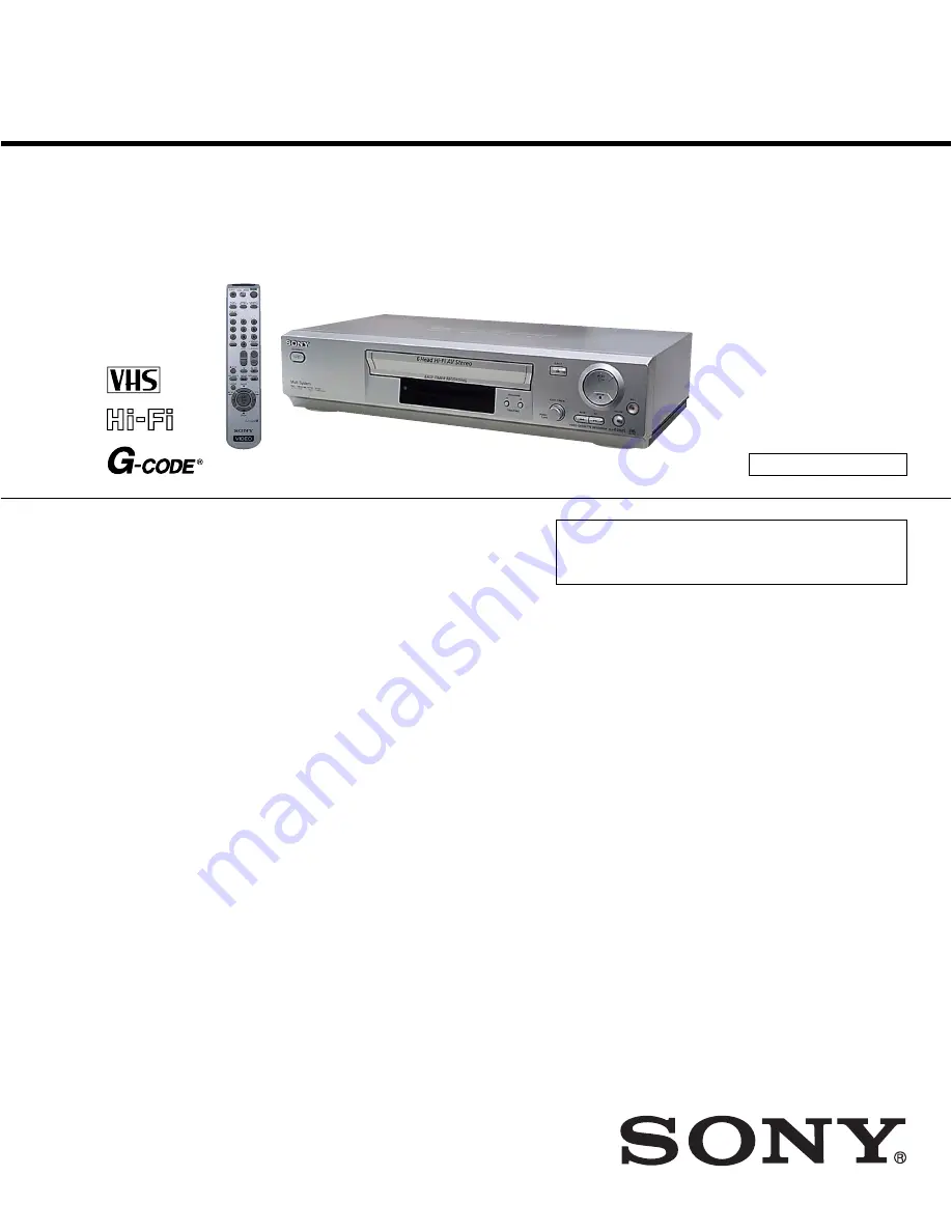
Photo: SLV-ED825PS

RMT-V408

— Continued on next page —

Middle East Model

SLV-ED323ME/ED323SG/ED828ME/ED828SG

E Model

SLV-ED225PS/ED825PS/ED925PS

Hong Kong Model

SLV-ED929MI

Australia Model

SLV-EZ121AZ/EZ424AZ/

EZ725AZ/EZ727AZ

SERVICE MANUAL

VIDEO CASSETTE RECORDER

TS-10 MECHANISM

Refer to the SERVICE MANUAL of VHS MECHANI-

CAL ADJUSTMENT MANUAL VII for MECHANICAL

ADJUSTMENTS. (9-921-790-11)

SPECIFICATIONS

SLV-ED225/ED323/ED825/ED828/ED925/ED929/

EZ121/EZ424/EZ725/EZ727

RMT-V408/V408A/V409

System

Colour system

ED225/ED323/ED825/ED828/ED925/ED929:

PAL, MESECAM, NTSC 3.58, NTSC 4.43

EZ727: PAL, NTSC 3.58, NTSC 4.43

EZ121/EZ424/EZ725: PAL, NTSC 4.43

TV system

ED929: B/G, D/K, I, NTSC-M

ED225/ED323/ED825/ED828/ED925: B/G, D/K, I

EZ121/EZ424/EZ725/EZ727: B/G, B/B

Channel coverage

B/G: VHF E2 to E12/UHF E21 to E69/CATV S01 to

S05, S1 to S41

B/B: VHF R1 to R12/UHF R21 to R69

D/K: VHF R1 to R12/UHF R21 to R69

I: VHF SA4 to SA13/UHF B21 to B69/CATV S01

to S05,S1 to S41

RF output signal

UHF channels 21 to 69 (G, I, K, B, M)

UHF channels 28 to 69 (B/B)

Aerial out

75-ohm asymmetrical aerial socket

Tape speed

ED929:

SP: PAL

23.39 mm/s (recording/playback)

NTSC 33.35 mm/s (recording/playback)

LP: PAL

11.70 mm/s (recording/playback)

NTSC 16.67 mm/s (playback only)

EP: NTSC 11.12 mm/s (recording/playback)

ED225/ED323/ED825/ED828/ED925/EZ727:

SP: PAL

23.39 mm/s (recording/playback)

NTSC 33.35 mm/s (recording (Line input only)/

playback)

LP: PAL

11.70 mm/s (recording/playback)

NTSC 16.67 mm/s (playback only)

EP: NTSC 11.12 mm/s (recording (Line input only)/

playback)

EZ121/EZ424/EZ725:

SP: PAL

23.39 mm/s (recording/playback)

NTSC 33.35 mm/s (playback only)

LP: PAL

11.70 mm/s (recording/playback)

NTSC 16.67 mm/s (playback only)

EP: NTSC 11.12 mm/s (playback only)

Maximum recording/playback time

10 hrs. in LP mode (with E300 tape)

Rewind time

Approx. 1 min.(with E180 tape)

Inputs and outputs

LINE IN 1/LINE-2 IN

VIDEO IN, phono jack (1)

Input signal: 1 Vp-p, 75 ohms,

unbalanced, sync negative

AUDIO IN, phono jack (2)

Input level: 327 mVrms

Input impedance: more than 47 kilohms

General

Power requirements

ED225/ED323/ED825/ED828/ED925/ED929:

110 – 240 V AC, 50/60 Hz

EZ121/EZ424/EZ725/EZ727:

220 – 240 V AC, 50 Hz

Power consumption

ED225/ED323/EZ121/EZ424: 15 W

ED825/ED828/ED925/ED929/EZ725/EZ727: 17 W

3 W (POWER SAVE is set to ON, minimum)

Operating temperature

°

C to 40 

°

C

Storage temperature

–20 

°

C to 60 

°

C

Summary of Contents for RMT-V408A

Page 1: ...al socket Tape speed ED929 SP PAL 23 39 mm s recording playback NTSC 33 35 mm s recording playback LP PAL 11 70 mm s recording playback NTSC 16 67 mm s playback only EP NTSC 11 12 mm s recording playback ED225 ED323 ED825 ED828 ED925 EZ727 SP PAL 23 39 mm s recording playback NTSC 33 35 mm s recording Line input only playback LP PAL 11 70 mm s recording playback NTSC 16 67 mm s playback only EP NT...

Page 2: ...tage to see it is at the values specified SAFETY RELATED COMPONENT WARNING COMPONENTS IDENTIFIED BY MARK 0 OR DOTTED LINE WITH MARK 0 ON THE SCHEMATIC DIAGRAMS AND IN THE PARTS LIST ARE CRITICAL TO SAFE OPERATION REPLACE THESE COMPONENTS WITH SONY PARTS WHOSE PART NUMBERS APPEAR AS SHOWN IN THIS MANUAL OR IN SUPPLEMENTS PUBLISHED BY SONY Abbreviation AUS Australia model HK Hong Kong model ME Middl...

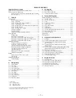
Page 3: ... 2 1 4 Ass y Main Board Deck 2 3 2 2 Hi Fi Models 2 2 1 Case Upper 2 4 2 2 2 Cover Bottom 2 4 2 2 3 Ass y Panel Front 2 5 2 2 4 Jack Board 2 5 2 2 5 Deck Main Board 2 6 3 P C Boards 3 1 Main PCB AUS 3 3 3 2 Main PCB E HK ME 3 7 3 3 Function PCB Hi Fi model 3 11 4 Schematic Diagrams Block Identification of Main PCB 4 3 4 1 S M P S AUS 4 5 4 2 S M P S E HK ME 4 7 4 3 Power 4 9 4 4 System Control Ser...

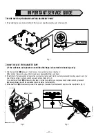
Page 4: ...See Fig 2 Other method Remove the screw of Motor Load Ass y Separate the Motor Load Ass y 2 When Slider S T are approached in the position of unloading rotate holder Clutch counterclockwise after inserting screw driver in the hole of frame s bottom in order to wind the unwiunded tape Refer to Fig 3 If you rotate Gear Worm 1 continuously when tape is in state of unwinding you may cause a tape conta...

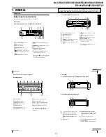
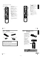
Page 5: ...ACKING button has a tactile dot continued 6 Getting Started Display window 1 Tape indicator 2 START indicator 37 3 STOP indicator 37 4 MONTH indicator 40 5 YEAR indicator 6 NICAM indicator 1 53 7 STEREO indicator 2 52 8 Timer indicator 39 43 46 9 Recording indicator 33 q Time counter clock line programme position indicator 31 32 62 qa Tape speed indicators 32 38 1 SLV ED929MI and ED925PS only 2 no...

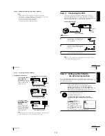
Page 6: ...e following items with the VCR Remote commander Aerial cable R6 size AA batteries Plug adaptor SLV ED828ME and ED323ME only Check your model name The instructions in this manual are for the 8 models SLV ED929MI ED925PS ED828ME SG ED825PS ED323ME SG and ED225PS Check your model name by looking at the rear panel of your VCR SLV ED929MI is the model used for illustration purposes Any difference in op...

Page 7: ...e not supplied For SLV ED929MI ED925PS ED828ME SG and ED825PS LINE OUT LINE IN Audio video cable not supplied For SLV ED323ME SG and ED225PS LINE OUT LINE IN Audio video cable not supplied To a stereo system not available on SLV ED323ME SG and ED225PS You can improve sound quality by connecting a stereo system to the LINE OUT AUDIO R L jacks as shown on the right Note To play a tape in stereo you ...

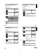
Page 8: ...tc will be reset If this happens you have to set them again Auto preset starts automatically only when you plug in the mains lead for the first time after you purchase the VCR After using the Auto Set Up function the LANGUAGE SET menu does not appear automatically when you connect the mains lead again If you want to use the Auto Set Up function again press MENU then press M m to highlight INSTALLA...

Page 9: ... EXIT MENU CLEAR DELETE SWAPPING OK TV STATION TABLE 5 4 3 2 1 0 0 0 0 3 3 2 2 2 0 9 7 I C L A J D M A K E N B B G D K B G D K B G D K B G D K PR CH NAME SYSTEM OK PLAY MENU OK END SELECT PR 5 SYSTEM B G D K MFT NAME SET EXIT MANUAL TUNING CH Presetting channels If some channels could not be preset using the Auto Set Up function you can preset them manually Before you start Turn on the VCR and the...

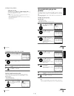
Page 10: ...K then press M m to move to the desired programme position 5 Press OK to confirm the setting 6 To change the programme position of another station repeat steps 3 through 5 7 Press MENU to exit the menu Disabling unwanted programme positions After presetting channels you can disable unused programme positions The disabled positions will be skipped later when you press the PROG buttons Before you st...

Page 11: ...channel 2 Insert a tape The VCR turns on and starts playing automatically if you insert a tape with its safety tab removed 3 Press H PLAY When the tape reaches the end it will rewind automatically Additional tasks To Press Stop play x STOP Pause play X PAUSE Resume play after pause X PAUSE or H PLAY Fast forward the tape M FF during stop Rewind the tape m REW during stop Eject the tape Z EJECT To ...

Page 12: ...al cable skip this step 2 Select another programme position on the TV To save a recording To prevent accidental erasure break off the safety tab as illustrated To record on the same tape again cover the tab hole with adhesive tape Safety tab To record NTSC colour system programmes For SLV ED929MI NTSC colour signals can be recorded on this VCR For SLV ED925PS ED828ME SG ED825PS ED323ME SG and ED22...

Page 13: ...rogramme position To record from other equipment connected to one or more of the LINE inputs turn EASY TIMER or press INPUT SELECT to display the connected line in the display window 9 Press EASY TIMER The current tape speed mode appears in the display window 10 Turn EASY TIMER to set the tape speed SP LP or AUTO EASY TIMER EASY TIMER INPUT SELECT EASY TIMER EASY TIMER Recording TV programmes usin...

Page 14: ...ther timer method after reconnecting the mains lead see page 50 SLV ED929MI only 42 Basic Operations Recording TV programmes using the G CODE system SLV ED929MI only The G CODE system is the feature that simplifies programming the VCR to make timer recordings Just enter the G code number listed in the TV programme guide The date times and programme position of that programme are set automatically ...

Page 15: ...OGRAMMING and press OK 2 Set the date start and stop times and tape speed 1 Press to select each item in turn 2 Press M m to set each item To correct a setting press to return to that setting and reset To record the same programme every day or the same day every week see Daily weekly recording on page 46 To record from other equipment connected to one or more of the LINE inputs press INPUT SELECT ...

Page 16: ...ndicator disappears and the VCR returns to the normal recording mode To stop recording To stop the VCR while recording press x STOP Note You cannot display the current tape time in the display window when setting the recording duration time 50 Additional Operations Checking changing cancelling timer settings Before you start Turn on your TV and set it to the video channel Refer to Index to parts a...

Page 17: ...ion The VCR automatically marks the tape with an index signal at the point where each recording begins Use these signals as references to find a specific recording To find a specific recording by scanning Index scan 1 Insert an indexed tape into the VCR 2 Press INDEX SEARCH The VCR starts scanning each recording for five seconds in the corresponding direction 3 Press H PLAY to start playback when ...

Page 18: ...ns 1 Press MENU then select USER SET or EASY OPERATION and press OK 2 Press M m to select the option 3 Press to change the setting then press OK Menu choices Initial settings are indicated in bold print USER SET Menu option Set this option to SET MENU OK END SELECT OSD ON ON TAPE SELECT E 1 8 0 COLOUR SYSTEM AUTO NICAM OFF POWER SAVE ON ASC EXIT EXIT SET MENU OK END SELECT G CODE EXTEND AUTO POWER...

Page 19: ...SET menu to OFF see page 57 Clock The clock has stopped and appears in the display window The clock stops if the VCR is disconnected from the mains Reset the clock and timer Playback The playback picture does not appear on the TV screen Make sure the TV is set to the video channel If you are using a monitor set it to video input If you made connections using the aerial cable only make sure the RF ...

Page 20: ...in the tape compartment The remote commander does not function Make sure you are pointing the remote commander at the remote sensor on the VCR Replace all the batteries in the remote commander with new ones if they are weak Make sure the TV VIDEO remote control switch is set correctly The selected input line connector number does not appear in the display window Press INPUT SELECT to display the c...

Page 21: ...m SLV ED225 ED323 ED825 ED828 ED925 ED929 EZ121 EZ424 EZ725 EZ727 2 1 1 CASE UPPER 2 1 2 COVER BOTTOM Case upper 2 Lift up the cabinet top in the direction of arrow by releasing the hook 1 Two screws 1 Release two snapfits 2 Lift up the bottom cover in the direction of arrow ...

Page 22: ...2 2 2 1 3 ASS Y PANEL FRONT Fig 2 3 Ass y Panel Front 1 Release four hooks 2 Release three hooks TOP VIEW ASS Y PANEL FRONT BOTTOM VIEW ...

Page 23: ...2 3 2 1 4 ASS Y MAIN BOARD DECK Fig 2 4 Ass y Main PCB Deck 1 Two screws 2 Bracket frame 7 Release hook PUSH 8 Ass y deck 9 Main board 6 Flat cable 3 Four screws 4 Flat cable 5 Flat cable ...

Page 24: ...p the bottom cover in the direction of arrow Case upper 2 Lift up the cabinet top in the direction of arrow by releasing the hook 1 Two screws 2 2 Hi Fi MODELS 2 2 1 CASE UPPER Fig 2 5 Cabinet Top Fig 2 6 Cover Bottom 2 2 2 COVER BOTTOM ...

Page 25: ...s y main and then lift the jack board up CN701 CN703 CN702 CN704 CN705 1 Release four hooks 2 Release three hooks TOP VIEW ASS Y PANEL FRONT BOTTOM VIEW 2 2 3 ASS Y PANEL FRONT Fig 2 7 Ass y Panel Front 2 2 4 JACK BOARD Fig 2 8 Jack Board ...

Page 26: ...2 6E 2 2 5 DECK MAIN BOARD Fig 2 9 Ass y Main PCB Deck 1 Two screws 2 Bracket frame 7 Release one tab 8 Ass y deck 9 Main board 6 Flat cable 3 Four screws 4 Flat cable 5 Flat cable ...

Page 27: ...3 3 Function PCB Hi Fi model 3 11 3 2 3 1 SLV ED225 ED323 ED825 ED828 ED925 ED929 EZ121 EZ424 EZ725 EZ727 Abbreviation AUS Australia model HK Hong Kong model ME Middle East model Hi Fi model ED825 ED828 ED925 ED929 EZ725 EZ727 Mono model ED225 ED323 EZ121 EZ424 ...

Page 28: ...3 1 MAIN PCB AUS 3 3 3 4 COMPONENT SIDE ...

Page 29: ...3 6 3 5 CONDUCTOR SIDE ...

Page 30: ...3 2 MAIN PCB E HK ME 3 7 3 8 COMPONENT SIDE ...

Page 31: ...3 10 3 9 CONDUCTOR SIDE ...

Page 32: ...3 3 FUNCTION PCB Hi Fi MODEL 3 11 3 12E COMPONENT SIDE CONDUCTOR SIDE ...

Page 33: ...7 TM Block 4 17 4 8 OSD VPS PDC 4 19 4 9 A2 NICAM ED925 ED929 EZ725 EZ727 4 21 4 10 Input Output RCA Jack 4 23 4 11 Sub Hi Fi model 4 25 Waveform 4 27 Voltage Table 4 29 4 2 4 1 SLV ED225 ED323 ED825 ED828 ED925 ED929 EZ121 EZ424 EZ725 EZ727 Abbreviation AUS Australia model HK Hong Kong model ME Middle East model Hi Fi model ED825 ED828 ED925 ED929 EZ725 EZ727 Mono model ED225 ED323 EZ121 EZ424 ...

Page 34: ... BLOCK IDENTIFICATION OF MAIN PCB Component Side Conductor Side 4 3 4 4 ...

Page 35: ...4 1 S M P S AUS PWR OFF PWR ON 1 2 4 6 4 5 ...

Page 36: ...4 2 S M P S E HK ME 4 7 4 8 PWR OFF PWR ON 1 2 ...

Page 37: ...4 3 POWER 4 10 4 9 ...

Page 38: ...6 5 7 3 4 0 8 9 4 4 SYSTEM CONTROL SERVO 4 11 4 12 ...

Page 39: ...4 5 AUDIO VIDEO VIDEO SIGNAL IN OUT LUMINANCE RECORDING LUMINANACE PLAYBACK CHROMA RECORDING CHROMA PLAYBACK AUDIO PROCESS IN AUDIO PROCESS OUT qs qd qh qa qg qf 4 14 4 13 ...

Page 40: ... AUDIOPBPROCESS AUDIORECPROCESS AUDIOPROCESS IN AUDIOPROCESS OUT C L IN AV L IN C R IN AUX R IN AV R IN TU L IN MTS MODEL 43K TU L IN AUX L IN 4 6 Hi Fi Hi Fi MODEL 4 15 4 16 ...

Page 41: ... VIDEOPROCESS IN VIDEOPROCESS OUT AUDIOPROCESS IN AUDIOPROCESS OUT qj 4 7 TM BLOCK 4 18 4 17 ...

Page 42: ... OSD VIDEO PROCESS IN OSD VIDEO PROCESS OUT qk 4 8 OSD VPS PDC 4 19 4 20 ...

Page 43: ...4 9 A2 NICAM ED925 ED929 EZ725 EZ727 4 21 4 22 ...

Page 44: ...AUDIO PROCESS OUT AUDIO PROCESS IN VIDEO PROCESS OUT VIDEO PROCESS IN 4 10 INPUT OUTPUT RCA JACK 4 23 4 24 ...

Page 45: ...4 11 SUB Hi Fi MODEL 4 25 4 26 ...

Page 46: ...1 24 0 9Vp p qs IC301 65 PB 2 1Vp p qh IC301 11 REC 102Vp p qd IC301 21 PB 320mVp p qf IC301 88 REC LP 2 5Vp p 4 IC601 9 PB 2 7Vp p 9 IC601 18 4 8Vp p 5 IC601 10 PB 2 7Vp p 0 IC601 100 PB 4 3Vp p 6 CN604 93 PB 5 1Vp p 7 IC610 97 PB 5 1V 2 Q1SR01 COLLECTOR POWER ON 400Vp p S M P S BLOCK TM BLOCK O S D BLOCK SYSTEM CONTROL SERVO BLOCK AUDIO VIDEO BLOCK 4 28 4 27 ...

Page 47: ... 2 67 0 2 0 2 0 2 68 4 7 4 7 4 7 69 4 5 4 7 4 5 70 2 8 5 2 2 8 71 0 0 3 3 3 3 72 5 0 5 0 5 0 73 1 9 2 2 2 2 74 2 6 2 5 2 5 75 0 7 2 4 2 4 76 0 8 2 4 2 4 77 1 6 1 5 1 5 78 3 4 2 6 2 5 79 1 9 1 9 2 5 80 0 9 0 9 4 2 81 1 1 1 1 1 1 82 0 0 0 0 0 0 83 2 6 0 7 0 0 84 2 7 0 6 0 0 85 0 0 0 0 1 0 86 0 4 0 4 0 0 87 0 7 1 9 2 5 88 0 7 1 9 0 7 89 0 7 1 9 0 7 90 0 7 1 9 0 7 91 5 2 5 2 4 1 92 0 0 0 0 0 0 93 1 9 ...

Page 48: ...4 32E MEMO ...
Page 49: ...just the X Point and Head switching adjustment 4 How to adjustment Press the TEST button on Main PCB Function PCB to set the adjustment mode If the corresponding adjustment button is pressed the adjustment is performed automatically If the adjustment is completed be sure to turn the power off 5 1 1 Location of adjustment button of remote control Fig 5 1 X Point Tracking Center Adjustment 5 Button ...

Page 50: ...5 2 PRESS Fig 5 2 Main PCB Top View 5 1 2 Test point location for adjustment mode setting EZ121 EZ424 ...

Page 51: ...5 3 PRESS Fig 5 3 Main PCB Top View 5 1 3 Test point location for adjustment mode setting ED225 ED323 ...

Page 52: ...5 4 TEST SW7T21 BUTTON Fig 5 4 Function PCB Top View 5 1 4 SW7T21 TEST location for adjustment mode setting ED825 ED828 ED925 ED929 EZ725 EZ727 ...

Page 53: ...ee the 5 2 1 d ACE Head Position X Point Adjustment on page 5 2 of the Mechanical Manual 1 Playback the alignment tape Color bar 2 Press the TEST button on Main PCB Function PCB to set the adjustment mode See Fig 5 2 5 3 and 5 4 3 Press the 5 button of remote control then adjustment is op erated automatically See Fig 5 1 4 Connect the CH 1 probe to TP301 Envelope the CH 2 probe to TP602 H D switch...

Page 54: ...he alignment tape 2 Press the TEST button on Main PCB Function PCB to set the adjustment mode See Fig 5 2 5 3 and 5 4 3 Press the SP LP button of remote control then adjustment is operated automatically See Fig 5 1 4 Turn the Power off 5 4 NVRAM OPTION SETTING Fig 5 6 Fig 5 7 Table 5 1 01 02 03 04 05 06 07 08 09 10 11 12 13 14 15 16 17 18 19 20 21 22 23 24 25 26 27 28 29 30 31 32 33 34 35 36 37 38...

Page 55: ...trument Assembly Mono Models 6 1 2 Instrument Assembly Hi Fi Models 6 1 3 Mechanical Parts Top Side 6 1 4 Mechanical Parts Bottom Side 6 2 Electrical Parts List Page 6 2 6 2 6 3 6 4 6 5 6 6 SLV ED225 ED323 ED825 ED828 ED925 ED929 EZ121 EZ424 EZ725 EZ727 ...

Page 56: ...s 1 3 076 021 01 PANEL FRONT EZ121 1 3 076 022 01 PANEL FRONT ED225 1 3 076 023 01 PANEL FRONT ED323 1 3 076 024 01 PANEL FRONT EZ424 2 3 076 017 01 DOOR CASSETTE 3 3 076 035 01 ASSY DECK 04 1 823 023 11 POWER CORD ED225 ED323 04 1 824 231 11 POWER CORD EZ121 EZ424 5 3 075 020 01 CASE UPPER 6 7 685 646 11 SCREW TAPTITE 8 1 477 367 11 REMOTE COMMANDER RMT V408 EXCEPT EZ424 8 1 477 368 11 REMOTE COM...

Page 57: ...POWER CORD ED825 ED828 ED925 ED929 054 1 824 231 11 POWER CORD EZ725 EZ727 55 3 075 019 01 CASE UPPER 56 7 685 646 11 SCREW TAPTITE 58 1 477 367 11 REMOTE COMMANDER RMT V408 ED825 ED828 ED925 EZ725 58 1 477 368 11 REMOTE COMMANDER RMT V408A ED929 58 1 477 369 11 REMOTE COMMANDER RMT V409 EZ727 59 3 075 088 01 DOOR BATTERY REMOCON for RMT V408 V408A V409 6 1 2 Instrument Assembly Hi Fi Models 53 55...

Page 58: ...SSY 107 3 067 783 01 BAND BRAKE ASSY 108 3 067 788 01 HOLDER FL CASS ASSY 109 1 796 440 11 DRUM ASSY ED323 109 1 796 441 11 DRUM ASSY ED828 109 1 804 708 11 DRUM ASSY ED225 EZ121 109 1 804 709 11 DRUM ASSY EZ424 109 1 804 710 11 DRUM ASSY ED825 ED925 ED929 EZ725 EZ727 111 1 796 433 11 DAMPER CAPSTAN 112 3 067 784 01 LEVER UNIT PINCH ASSY 114 3 709 671 01 ASSY HEAD ACE 115 3 067 789 01 GUIDE CASS D...

Page 59: ...ied not supplied 7 6 not supplied not supplied not supplied not supplied not supplied not supplied not supplied 151 152 Ref No Part No Description Remarks Ref No Part No Description Remarks 151 3 067 790 01 BELT PULLEY 152 1 796 432 11 MOTOR CAPSTAN ...

Page 60: ...1 ELECT 82uF 20 400V E HK ME C1SD11 1 165 577 11 ELECT 47uF 20 400V AUS C1SD12 1 165 574 11 FILM MPEF 10nF 10 630V C1SD13 1 165 991 11 CERAMIC DISC 0 22nF 5 50V E HK ME C1SD13 1 165 567 11 FILM PEF 1 2nF 10 50V AUS C1SF12 1 126 966 11 ELECT 33uF 20 50V E HK ME C1SR12 1 124 285 11 ELECT 22uF 20 16V AUS C1SR14 1 165 571 11 FILM PEF 4 7nF 5 50V AUS 0C1SS01 1 165 573 11 FILM MPEF 100nF 20 275V 0C1SS02...

Page 61: ...27 C4N17 1 163 267 11 CERAMIC CHIP 0 47nF 5 50V ED925 ED929 EZ725 EZ727 C4N18 1 163 267 11 CERAMIC CHIP 0 47nF 5 50V ED925 ED929 EZ725 EZ727 C4N23 1 126 458 61 ELECT 1uF 20 50V ED925 ED929 EZ725 EZ727 C4N24 1 126 458 61 ELECT 1uF 20 50V ED925 ED929 EZ725 EZ727 C4N26 1 126 458 61 ELECT 1uF 20 50V ED825 ED828 C501 1 126 109 11 ELECT 10uF 20 16V Hi Fi model C502 1 115 339 11 CERAMIC CHIP 100nF 10 50V...

Page 62: ...7 11 DIODE 1N4148 D704 1 804 407 11 DIODE 1N4148 DT701 1 518 827 11 LED DISPLAY LTG 0132M LD601 1 804 438 11 LED IR T S LED LDT01 1 804 796 11 LED IR ZD1P01 1 804 416 11 DIODE MTZJ5 1B Hi Fi model ZD1P02 1 804 416 11 DIODE MTZJ5 1B ZD1P03 1 804 417 11 DIODE MTZJ9 1B Hi Fi model ZD1P04 1 804 417 11 DIODE MTZJ9 1B ZD1SS1 1 804 415 11 DIODE UZP43B AUS ZD801 1 804 803 11 DIODE MTZ6 2B ED225 FUSE 0F1SS...

Page 63: ...1K 5 1 8W E HK ME R1SF20 1 216 363 11 METAL OXIDE 0 33 5 2W E HK ME R1SF21 1 247 903 11 CARBON 1M 5 1 2W E HK ME R1SR11 1 216 367 11 METAL OXIDE 0 68 5 2W AUS R1SR12 1 244 369 11 METAL OXIDE 300 5 1W AUS R1SR14 1 247 819 11 CARBON 330 5 1 8W AUS R1SS03 1 245 346 11 R FUSIBLE 10 5 2W AUS EZ121 EZ424 E HK ME R1SS10 1 244 373 11 R CEMENT 2 7 10 2W R1SS11 1 215 901 11 METAL OXIDE 33K 5 2W R1SS32 1 216...

Page 64: ...875 11 CARBON 68K 5 1 8W R661 1 216 687 11 RES CHIP 33K 5 1 10W R666 1 216 643 11 RES CHIP 470 5 1 10W R667 1 216 643 11 RES CHIP 470 5 1 10W R668 1 216 675 11 RES CHIP 10K 5 1 10W R669 1 216 675 11 RES CHIP 10K 5 1 10W R670 1 216 667 11 RES CHIP 4 7K 5 1 10W R671 1 216 667 11 RES CHIP 4 7K 5 1 10W R672 1 216 667 11 RES CHIP 4 7K 5 1 10W R675 1 247 813 11 CARBON 180 5 1 4W R676 1 216 686 11 RES CH...

Page 65: ...R CORD EZ121 EZ424 054 1 823 023 11 POWER CORD ED825 ED828 ED925 ED929 054 1 824 231 11 POWER CORD EZ725 EZ727 109 1 796 440 11 DRUM ASSY ED323 109 1 796 441 11 DRUM ASSY ED828 109 1 804 708 11 DRUM ASSY EZ121 ED225 109 1 804 709 11 DRUM ASSY EZ424 109 1 804 710 11 DRUM ASSY ED825 ED925 ED929 EZ725 EZ727 118 1 796 434 11 MOTOR LOADING ASSY 152 1 796 432 11 MOTOR CAPSTAN HARDWARE LIST 1 7 685 548 1...

Page 66: ... 88 Sony Corporation Home Video Company 9 929 726 11 2002D0500 1 2002 4 Published by Quality Assurance Dept SLV ED225 ED323 ED825 ED828 ED925 ED929 EZ121 EZ424 EZ725 EZ727 ...

Reviews: