background image

Summary of Contents for SLV-360

Page 1: ...i I H MECHANISM OPERATION MANUAL S ...

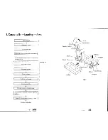
Page 2: ...t diagram 3 2 Tape path 4 3 Cassette IN _ Loading _ Stop 5 4 Stop _ Playback 11 5 Stop _ Power OFF 13 6 Playback _ CUE 15 7 Playback _ REV 17 8 Stop _ Fast forward FF 19 9 Stop _ Rewind REW 23 10 Stop _ Unloading _ Eject 27 1 16 ...

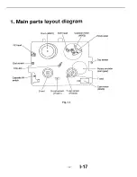
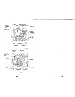
Page 3: ...gram FE head End sensor T S LED _ Cassette IN switch _ S reel Pinch roller T S reel sensor PH401 Top sensor Rotary encoder ot _ Q____ __ I _ L__ cam gea r _ _ _ I_ _ T reel _ Cam motor M903 T reel sensor PH402 Fig 1 1 3 1 17 ...

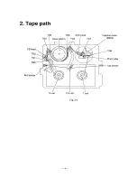
Page 4: ...2 Tape path TG4 TG5 ACE head Capstan motor S reel T S LED T reel Fig 2 1 4 ...

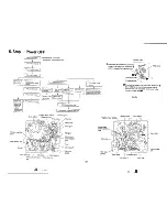
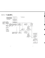
Page 5: ... is rotated Cam gear is rotated I FL driving gear is rotated i Gear slide plate slides I Relay gear rotates to swing right left arm t Cassette holder is retracted to set cassette in DOWN position Cassette IN switch is pressed by cassette IN lever Continues to loading see Page 7 8 Cassette Cassette IN switch Left claw IN lever Leftarm Cassette IN levi Cassette holder Cassette Fig 3 1 Right claw FL ...

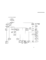
Page 6: ... released from S reel RKB block is clutched ON by RKB arm f Capstan I Pendulum brakeis I compulsionarm Ireleased I isoperated fromcapstan I Pendulum gear _ isfreeonT reelI side only TG8 arm loading Upper Lower commu nication gear is rotated t i TG8 gear is I I rotated 22 Elevator gear is rotated L Pinch roller moves down Brake is given toT reel from reverse brake arm and released immediately Pinch...

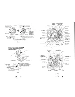
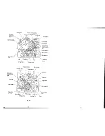
Page 7: ...KB arm pushed up by step _ moves in the direction of arrow mark I_ _ Main slider arm brock Timing belt Pendulum g Pendulum gear RKB brock I _ RKB arm moves in the direction of arrow mark e then RKB block moves in the direction of arrow mark _ to change the mesh of pendulum gear Timing belt Fig 3 3 Shuttle T Drum M901 TG1 arm Shuttle S Tension regulator band Fixed release arm Soft brake S Pendulum ...

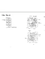
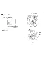
Page 8: ...elt clutch ON Pendulum gear is meshed with idler gear T and rotated T reel is rotated I f 11 Drum M901 Capstan motor M902 1 Capstanshaft J RKB brock T reel Idler gear T _ j Pinch roller Pendulum compulsion arm Capstan motor RKB brock T re _el M_02 Idler gear T Pendulum gear Idler gear S Tensionwheel Timing belt Fig 4 1 ...

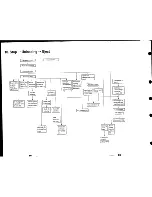
Page 9: ...oS I reel movesdown t RKB block becomesfree I Pendulumgearis releasedfrom T reel Capstan shaft Pinch block is operated and pinch roller moves in the direction of arrow mark O until it is released from capstan shaft _ Pinch brock pin J_ Press gear cam j Pinch block O Press gear is rotated in the direction of arrow mark O and pinch block pin pushed to press gear cam is released from cam while pinch ...

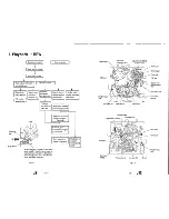
Page 10: ...ted at high speed I Pinch roller is rotated I i L at high speed _ Difference from Stop Playback Capstan motor is rotating at high speed g Pendulum gear is meshed with idler gear T from the beginning 1 RKBbrock RKB brock T reel Drum M901 Capstan motor M902 Capstan shaft Pinch roller Pendulumgear T reel Idler gear S Idler gear T Capstan motor Mi02 Idler gear T Pendulum gear Tension wheel ___ Timing ...

Page 11: ...ection of arrow mark S winding arm pressed by main slider cam moves inthe direction of arrow mark _ and S reel is rotated a little in the direction of arrow mark RKB block is rotated through timing belt clutch ON i Pendulum gear is meshed with idler gear S and rotated S reel is rotated in reverse at high speed _r Pinch roller is rotated in reverse at high speed Fig 7 1 Drum Fixed arm RKB Pendulum ...

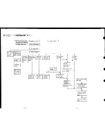
Page 12: ...apstan motor by capstan brake v Capstan brake is released from capstan motor Brake is given to S reel by main brake S Main brake S is released from S reel Brakeis given I to T reel by main brake if Main brake T isreleased form T reel Drumis rotating r Pendulum compulsionarm is operated Neutrality arm is operated f I r e everl slides I Pendulum gear is locked in the centerbetween S reel andT reel N...

Page 13: ... Upper Lower communication gear Cam gear RKB brock Cam motor M903 Capstan motor M902 Worm wheel T reel Capstan brake Drum M901 Tension wheel Trigger lever RKB arm Pendulum gear Idler Fig 8 1 gear Pinch block Press gear Upper Lower _mmunication gear Neutrality arm Main brake T brake T Cam motor M903 Main slider Timing belt Main brake S Fixed release arm J15 J16 ...

Page 14: ... I I Brake is given to S reel by main brake S Capstan brake is released from capstan motor f Main brake S is released from S reel I Brake is given to T reel by main brake T I Main brake T 1 is released form T reel Drum is rotating Triggerlever slides I I I Neutrality arm is operated r Neutrality arm is operated again I _f IPendulum compulsion ann is operated Pendulum gear is locked in thecenter be...

Page 15: ... wheel Idler gear T Capstan motor M902 Capstan shaft TG8 gear Pinch roller RKB brock T reel Pendulum gear Capstan brake Drum M901 Tension wheel Pendulum gear RKB arm Idler _ear S S reel Fig 9 1 gear Pinch block Press gear Upper Lower mmunication gear LJtrality arm Main brake T Soft brake T Cam motor M903 slider Timing belt Trigger lever Main brake S Fixed release arm ...

Page 16: ...tated I __3 Shuttle S unloading Shuttle T unloading k rum cleaning by MC roller Pendulum Reverse brake compulsion arm gives arm _soperated ibrake to T reel Pendulum gear andis released is free on Sreel immediately only RKB block is set in clutch OFF by RKB arm Upper Lower communication gear is rotated I I Press gear is rotated I I Pinch roller is Elevator gear is released from Irotated 1 capstan m...

Page 17: ...m S reel Fig 10 1 0 Main slider moves in the direction of arrow mark 0 and RKB arm is pushed up in the direction of arrow mark by step Main slider O RKB arm RKB brock Pendulum gear belt When RKB arm moves inthe direction of Pendulumgear RKB brock j arrow mark 0 RKB block moves inthe 1_ _ direction of arrow mark _ to change I r I I i_ l _ the mesh of pendulum gear o i Fig 10 2 Pinch roller moves up...

Page 18: ...tated to swing i right left arm form cassette 1Nswitch Cassette IN switch is pressed by cassette IN lever l Cam motor stops I I Cassette holder slides 1 Cassette is ejected I Left arm Door Cassette IN lever Cassette holder FL driving gear Right arm Gear slide plate Cassette Relay gear Fig 10 4 ...

Reviews: