


SER
SER
SER
SER
SERVICE MANUAL
VICE MANUAL
VICE MANUAL
VICE MANUAL
VICE MANUAL
BA-4D
BA-4D
BA-4D
BA-4D
BA-4D
CHASSIS
CHASSIS
CHASSIS
CHASSIS
CHASSIS
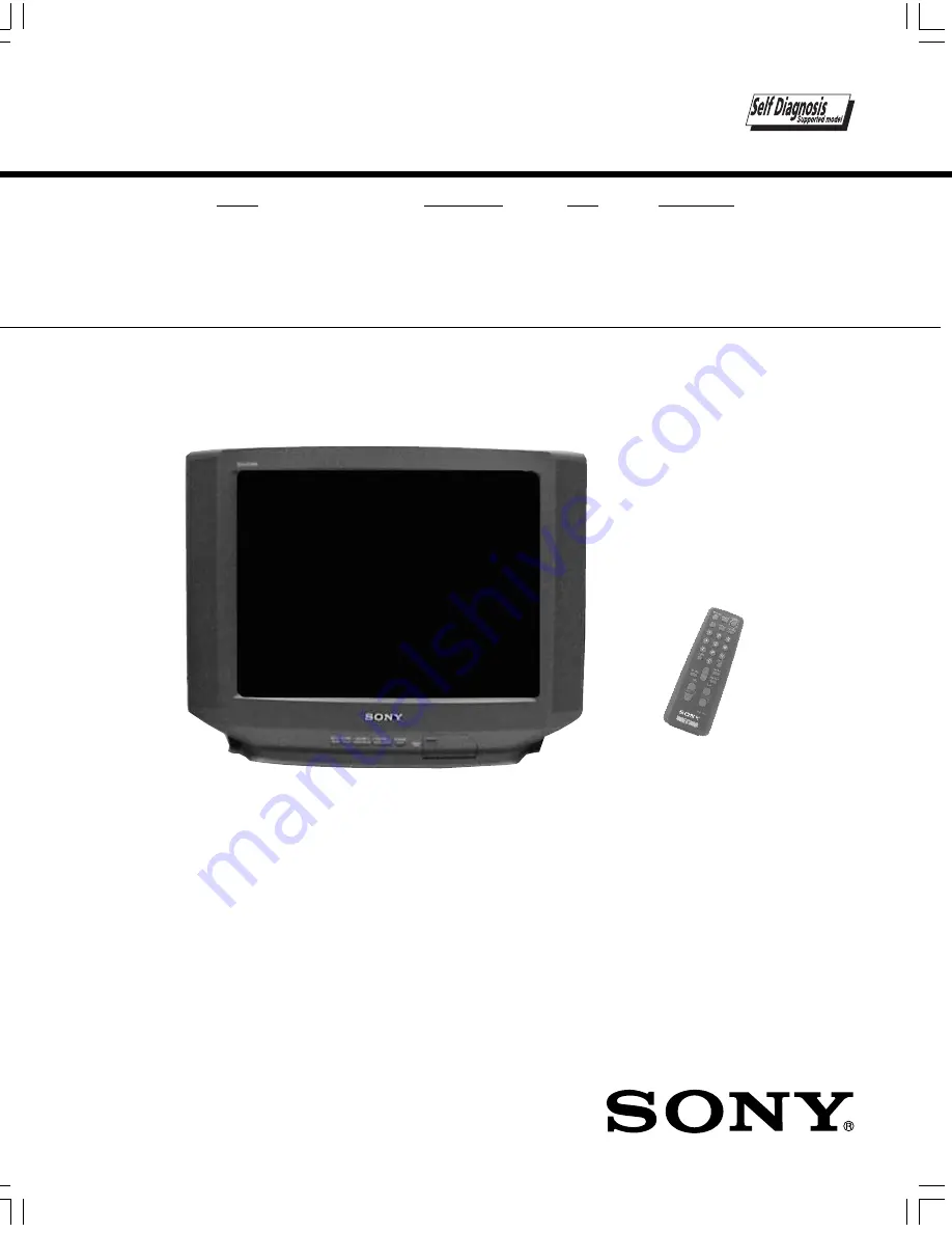
MODEL
COMMANDER
DEST
CHASSIS NO.
KV-21ME43
KV-21ME43
KV-21ME43
KV-21ME43
KV-21ME43
RM-Y156
E
SCC-S55A-A
TRINITRON
TRINITRON
TRINITRON
TRINITRON
TRINITRON
®
®
®
®
®
COLOR TV
COLOR TV
COLOR TV
COLOR TV
COLOR TV
RM-Y156
KV-21ME43
900 Cover.p65
11/30/00, 8:09 AM
1
Summary of Contents for TRINITRON RM-Y156
Page 24: ... 24 KV 21ME43 KV 21ME43 KV 21ME43 KV 21ME43 KV 21ME43 NOTES ...
Page 25: ... 25 KV 21ME43 KV 21ME43 KV 21ME43 KV 21ME43 KV 21ME43 NOTES ...
Page 26: ... 26 KV 21ME43 KV 21ME43 KV 21ME43 KV 21ME43 KV 21ME43 NOTES ...
Page 38: ... 86 NOTES NOTES 50 KV 21ME43 KV 21ME43 KV 21ME43 KV 21ME43 KV 21ME43 ...