background image

Conf

idential

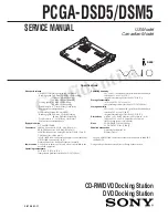
SERVICE MANUAL

US Model

Canadian Model

PCGA-DSD5/DSM5

S400

9-872-201-11

CD-RW/DVD Docking Station

DVD Docking Station

Drive performance

CD-RW/DVD Docking Station (PCGA-DSM5)

                            Reading speed: 24X max. CD-ROM/CD-R reading,
                                                        12X max. CD-RW reading,
                                                        8X max. DVD-ROM reading,
                            Writing speed:  8X max. CD-R writing,
                                                        4X max. CD-RW writing,
                            Disk diameter   4 

3

/

inch (12cm), 3inch (8cm)

                            Multi-session correspondence


DVD Docking Station (PCGA-DSD5)

                            Reading speed: 24X max. CD-ROM reading,
                                                       : 8X max. DVD-ROM reading,
                            Disk diameter  4 

3

/

inch (12cm), 3inch (8cm)

                            Multi-session correspondence

Floppy disk drive

3.5" 1.44MB/720KB

Connectors

SERIAL Connector: RS-232C, D-SUB 9 pin (1)
PRINTER Connector: ECP, D-SUB 25 pin (1)
MONITOR Connector: analog RGB, mini D-SUB 15 pin (1)
USB Connector: USB 4 pin (2)
i.LINK (IEEE 1394) Connector S400 4pin(1)  S400=400Mbps
NETWORK Connector: RJ-45 (1)*
Docking Connector: 

Dedicated connector 100

pin(1)

Power source

AC adapter or battery pack (only when it is attached to the
notebook computer)

Operating temperature

41 

°

F to 95 

°

F (5 

°

C to 35 

°

C)

(temperature gradient less than 18 

°

F (10 

°

C)/hour)

Operating humidity

20 % to 80 % (not condensed), provided that humidity is
less than 65 % at 95 

°

F (35 

°

C)

(hygrometer reading of less than 84 

°

F (29 

°

C))

Storage temperature

–4 

°

F to 140 

°

F (–20 

°

C to 60 

°

C)

(temperature gradient less than 18 

°

F (10 

°

C)/hour)

Storage humidity

10 % to 90 % (not condensed), provided that humidity is
less than 20 % at 140 

°

F (60 

°

C)

(hygrometer reading of less than 95 

°

F (35 

°

C))

Dimensions

Approx. 11.0 

×

 0.8(0.9

 backside

×

 9.3 inches (w/h/d)

(Approx. 279.5 

×

 18.5(

21.5 backside

×

 235.0 mm)

(

the projecting parts are not included

)

Mass

PCGA-DSM5 2.38 lbs. (1,080 g)
PCGA-DSD5 2.27 lbs. (1,030 g)

Supplied accessories

Operating instructions (1)

Warranty card (1)

* There is a NETWORK Connector for the correspondence to 10BASE-T,

100BASE-TX.

Design and specifications are subject to change without notice.

Specifications

Summary of Contents for Vaio PCGA -DSD5

Page 1: ...nector RJ 45 1 Docking Connector Dedicated connector 100pin 1 Power source AC adapter or battery pack only when it is attached to the notebook computer Operating temperature 41 F to 95 F 5 C to 35 C temperature gradient less than 18 F 10 C hour Operating humidity 20 to 80 not condensed provided that humidity is less than 65 at 95 F 35 C hygrometer reading of less than 84 F 29 C Storage temperature...

Page 2: ...ep it away from hot or high voltage parts When mounting parts or routing wires therefore be sure to duplicate the original layout 4 Inspect after completing service After servicing inspect to make sure that all screws components and wiring have been returned to their original condition Also check the area around the repair location to ensure that repair work has caused no damage and confirm safety...

Page 3: ...ssy 2 2 2 COMBO Drive DVD ROM 2 2 3 FDD 2 3 4 IRX 146 Board 2 3 5 CNX 130 Board 2 4 6 SWX 75 Board 2 4 7 CNX 132 Board 2 5 to 2 5 CHAPTER 3 SELF DIAGNOSTICS 3 1 Please confirm Self Diagnostics method which will be informed you with distribution of Self Diagnostics software CHAPTER 4 BLOCK DIAGRAM 4 1 to 4 2 CHAPTER 5 FRAME HARNESS DIAGRAM 5 1 to 5 2 CHAPTER 6 EXPLODED VIEWS AND PARTS LIST 6 1 Main...

Page 4: ...amp page 65 5 Release lever page 67 Docking station top Docking station right side Locating Controls and Connectors 62 Docking Station Left Side Rear 1 Release lever page 67 2 Ventilator 3 Floppy disk drive 4 i LINK network switch page 91 5 DC IN connector page 65 6 network connector page 6 7 USB connector 8 S400 i LINK connector 9 a MONITOR connector 0 PRINTER connector qa SERIAL connector Dockin...

Page 5: ...compatible unit first when removing the docking station during the connection of i LINK compatible unit The message Recording to DV unit failed Retry after checking the DV unit for power supply and connection state is displayed during the recording on the tape using the DVgate software t Check if the power and connection cables are connected correctly to the DV unit Continuous recording may cause ...

Page 6: ...this manual 2 2 Main Electrical Parts Location Diagram POWER OFF HOUSING TOP ASSY P 2 2 COMBO DRIVE DVD ROM P 2 2 FDD IFX 146 BOARD SWX 75 BOARD P 2 3 P 2 3 P 2 4 CNX 132 BOARD CNX 130 BOARD P 2 4 P 2 5 CNX 130 Board FDD COMBO Drive PCGA DSM5 DVD ROM PCGA DSD5 SWX 75 Board CNX 132 Board IFX 146 Board ...

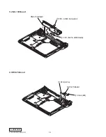
Page 7: ... Confidential 2 3 Removal 1 Housing Top Assy 2 COMBO Drive DVD ROM 2 1 P2 6X8 1 P2 6X8 Housing Top Assy 1 P2 6X8 1 M2X3 Can remove the drive by taking off three screws 2 FPC 50 Pin 3 COMBO Drive PCGA DSM5 DVD ROM PCGA DSD5 ...

Page 8: ...al 3 FDD 3 Bezel FDD Assy 1 FFC 26 Pin For FDD 2 FDD 4 IRX 146 Board 2 FFC 26 Pin For FDD 3 FPC i LINK Connector 4 FFC 54 Pin With Shield IFX 146 Board 8 Harness Power 3P 9 RJ 45 Harness For Internal 5 FFC 6 Pin 1 FPC 50 Pin 6 Claw 7 ...

Page 9: ...2 4 PCGA DSD5 DSM5 UC Confidential 5 CNX 130 Board 6 SWX 75 Board CNX 130 Board 1 FPC i LINK Connector 2 FFC 54 Pin With Shield 3 3 Knob UD 2 1 FFC 6 Pin SWX 75 Board ...

Page 10: ...2 5 PCGA DSD5 DSM5 UC Confidential 7 CNX 132 Board END 1 Harness Power 3P 2 CNX 132 Board ...

Page 11: ...3 1 PCGA DSD5 DSM5 UC Confidential CHAPTER 3 SELF DIAGNOSTICS END ATTENTION Please confirm Self Diagnostics method which will be informed you with distribution of Self Diagnostics software ...

Page 12: ...ing Connector VGA Ethernet i LINK Bridge Chip Optical Disc Drive ATAPI PHY LINK DOCKED DC IN VCC5 H8 RESET IC UNDOCK SW i LINK Network SW SUS_ON USB_EN UNDOCK_SW Docking Station Indicator D_INUSE MPBID1 ICH PCG R505 Side Docking Station Side i LINK I F i LINK I F D_SUSPEND RSRV_ID INUSE_LED USB Atype DSUB 25 DSUB 9 DSUB 15 RJ 45 i LINK 4 x 2 BUS SW FD I F FD I F FDDBUS 4 1 4 2 CHAPTER 4 BLOCK DIAG...

Page 13: ...503 MONITOR CN505 PRINTER CN504 SERIAL CN501 54 1 CN502 1 9 2 10 CN201 3 1 CN304 8 1 CN301 6 1 CN400 DC IN i LINK NETWORK SW 1 6 CN300 100 99 2 1 1 50 26 CN303 1 1 26 CN302 54 1 1 10 CN101 Rear S500 UNDOCK SW S400 NOTEBOOK COMPUTER PCG R600 SERIES Side R Side L FPC 50PIN FFC 26PIN FOR FDD FFC 6PIN HARNESS POWER 3P FFC 54PIN WITH SHIELD FPC iLINK CONNECTOR RJ 45 HARNESS FOR INTERNAL FROM board conn...

Page 14: ...TED PWB CNX 132 21 1 961 140 21 HARNESS RJ 45 FOR INTERNAL 22 4 652 982 01 SPRING SLIDER COIL 23 4 652 968 01 SLIDER R 24 4 652 965 01 HOOK R 25 4 652 981 01 SPRING HOOK COMPRESSION COIL 26 4 652 993 01 SHAFT 27 4 652 980 01 SPRING R TORSION 28 4 652 963 01 LEVER R 29 1 815 681 11 FFC 6 PIN 30 A 8066 659 A MOUNTED PWB SWX 75 31 4 652 961 01 KNOB UD 32 X 4623 680 1 HOUSING BOTTOM ASSY 33 4 641 449 ...

Page 15: ...PCGA DSD5 DSM5 UC Confidential 6 3 6 4 Ref No Part No Description ACCESSORIES 4 653 715 11 MANUAL INSTRUCTION 6 2 Accessories MEMO END ...

Page 16: ... 1 2001 Sony Corporation Published by MNC IT Planning Control Dept SODP This manual and the constituent data may not be replicated copied nor reprinted in whole or in part without prior written authorization of Sony Corporation PCGA DSD5 DSM5 UC 9 872 201 11 2001D0500 1 ...

Reviews: