background image

 2004 Sony Corporation

Digital Video
Camera Module

A-C3H-100-11 (1)

Technical Manual

XCL-X700/V500

Summary of Contents for XCL-V500

Page 1: ... 2004 Sony Corporation Digital Video Camera Module A C3H 100 11 1 Technical Manual XCL X700 V500 ...

Page 2: ...e Camera Functions 13 Electronic Shutter Function 13 Overlap Function 13 External Clock Input Function 15 Binning Function 16 High rate scan I Function 17 High rate scan II Function 19 Input Output Signal Specifications 24 External HD VD input phase specifications 24 External HD Input Specifications 25 External VD Input Specifications 25 HD VD Output Specifications only for the DC IN connector 25 ...

Page 3: ... Input Specifications 40 HD VD Output Specifications only for the DC IN connector 40 Trigger Pulse Specifications 41 WEN Output Specifications only for the DC IN connector 41 LVAL FVAL Output Specifications only for the DIGITAL IF connector 41 External CLK Specifications common to the DC IN DIGITAL IF connectors 41 CCD Output Waveform Timing Chart 42 Camera Control Command Overview 43 Serial Commu...

Page 4: ...ped with a Camera Link compatible connector The XCL X700 can output a digital image at 30 frames per second the XCL V500 can output a digital image at 60 frames per second High image quality The XCL X700 XGA has a progressive scan CCD of 800 000 pixels The XCL V500 VGA has a progressive scan CCD of 330 000 pixels Both cameras produce high resolution images By adopting square pixels images can be p...

Page 5: ...ve video output lines to achieve high frame rates enabling high speed image processing Binning By binning two pixels that align vertically you can acquire sensitivity as well as a frame rate twice as high as those in the normal mode when using the electronic shutter Body fixing The screw holes to install the camera module are located under the front panel the CCD reference plane Installing the cam...

Page 6: ...mera Link cable 1MA26 4560 OSC 200 2 m 6 6 ft 500 5 m 16 4 ft A00 10 m 32 8 ft Sony camera compatible cable produced by Sumitomo 3M Limited commercially available Camera adaptor DC 700 700CE Connection Diagram C mount lens VCL 08YM VCL 12YM VCL 16Y M VCL 25Y M VCL 50Y M Close up ring kit LO 77ERK XCL X700 V500 Tripod adaptor VCT 333I Camera cables CCXC 12P02N CCXC 12P05N CCXC 12P10N CCXC 12P25N Ca...

Page 7: ... project more than 7 mm 9 32 inch from the lens mount 2 Guide holes at the top These screw holes help to lock the camera module 3 Tripod screw holes at the bottom These four screw holes on the bottom are for installing the camera module on a tripod To install on a tripod you will need to install the VCT 333I tripod adaptor using these holes on the bottom of the camera 4 Reference holes at the bott...

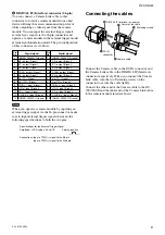
Page 8: ... Ground 6 HD output Signal HD input Signal HD input Signal HD input Signal 7 VD output Signal VD input Signal Reset Signal VD input Signal 8 9 Clock input Signal Clock input Signal Clock input Signal Clock input Signal 10 WEN output Signal 11 Trigger pulse input Signal 12 VD output Ground VD input Ground Reset Ground VD input Ground Note When you operate a camera module by inputting an external cl...

Page 9: ... input Signal 10 HD input Signal 23 HD input Signal 11 VD input Signal 24 VD input Signal 12 CLOCK input Signal 25 CLOCK input Signal 13 INNER_SHIELD Ground 26 INNER_SHIELD Ground Connecting the cables Connect the Camera cable to the DC IN connector and the Camera Link cable to the DIGITAL IF Interface connector respectively When you connect the Camera Link cable turn the two Fastening screws on t...

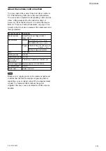
Page 10: ...ger mode 1 trigger mode 2 Shutter speed Normal XCL X700 OFF 1 30 1 20000 XCL V500 OFF 1 60 1 30000 Trigger Internal setting OFF the same as above 1 100000 Setting by trigger pulse width Gain 0 to 18 dB Binning function OFF ON High rate Scan function OFF ON HD VD signal I O External sync signal input Internal sync signal output External trigger input 26 pin connector DC 700 700CE 75 Ω termination O...

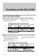
Page 11: ...s each independent pixel video signal of a single shot for which exposure time is proportional to the interval of External VD signals synchronized with External VD signals External synchronization is recommended Application Use this mode when you cannot gain Normal Mode when operating in external synchronization Restart Reset mode when operating in external synchronization 1 29 2 s 796H 1 29 2 s 7...

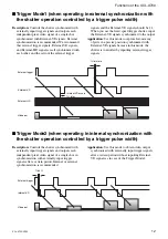
Page 12: ...se this mode to capture fast moving objects in a precise position synchronized with External VD signals because in this mode the shutter is controlled by inputting external trigger signals Trigger Mode2 when operating in internal synchronization with the shutter operation controlled by a trigger pulse width Description Controls the shutter synchronized with externally input trigger signals and out...

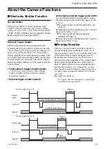
Page 13: ...r pulse width to the range of 2 µsec to 1 4 sec When trigger signals are input through the 12 pin connector External trigger pulse width shutter speed external trigger pulse width 6 µsec When trigger signals are input through the DIGITAL IF connector External trigger pulse width shutter speed external trigger pulse width 5 µsec Overlap Function One way to increase frame rate while using slow to mi...

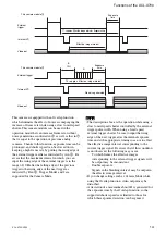
Page 14: ...rox Effective image interval Exposure time Effective image interval Internal VD External trigger Video out This camera module 2 T2 approx Effective image interval No noise generated B A 10H Exposure time Notes The description above is the operation while using a slow to mid speed shutter controlled by the external trigger pulse width When using a fixed speed external trigger shutter be sure to inp...

Page 15: ...nal HD signals depending on the timing when the power is turned on The amount of the shift is not always the same and varies within the range described above every time the power is turned on Be aware that noise is generated when the Internal External clock is switched By utilizing the external clock input function clock jitter is completely eliminated All modes are supported for the Camera Mode P...

Page 16: ...lse width shutter speed When trigger signals are input through the 12 pin connector Exposure time external trigger pulse width 1 µs 144 2 ECLK When trigger signals are input through the DIGITAL IF connector Exposure time external trigger pulse width 144 2 ECLK Shutter speed 1 Exposure time Be aware that the external trigger pulse width should be set in the range of 3 µsec to 1 4 sec when inputting...

Page 17: ...d by manipulating the setting of the low width of the External VD signals and the trigger interval You also need to make the external trigger interval setting for Trigger Mode1 Only Restart Reset mode and Trigger Mode1 are supported for the Camera Mode Only the external trigger pulse width shutter is supported for the electronic shutter External trigger External VD Trigger interval 1H or more 1H 2...

Page 18: ...High rate scan I OFF 28 766 387 19 30 355 258 24 35 221 193 27 38 153 Trigger Mode1 Binning ON Trigger interval H External VD width H BLKG width H Effective Lines H 398 High rate scan I OFF 28 368 193 19 30 101 129 24 35 92 Notes Frame rate is equal to the External VD Trigger interval in the settings indicated above This is the highest frame rate The settings for Trigger Mode1 indicated above appl...

Page 19: ...ical sections are set by the external trigger input interval and then inputting a command Necessary sections corresponding to the effective image interval and less critical sections to be transferred at high frame rates are designated and controlled by FPS RPS settings Only Trigger Mode2 is supported for the Camera Mode Only the external trigger pulse width shutter is supported for the electronic ...

Page 20: ...h rate scan II on the following page apply to the setting of slow to middle shutter speeds controlled by the external trigger pulse width while using the Overlap function When using middle to high speed shutter speeds input the external trigger setting value of the external trigger interval on the following page 1H without using the Overlap function as indicated in the timing chart above The timin...

Page 21: ...terval H FPS RPS Effective Lines H 751 0 1 720 711 0 2 672 671 0 3 624 631 0 4 576 591 0 5 528 551 0 6 480 511 0 7 432 471 0 8 384 431 0 9 336 391 0 10 288 351 0 11 240 311 0 12 192 271 0 13 144 231 0 14 96 191 0 15 48 Trigger interval H FPS RPS Effective Lines H 697 1 1 662 657 1 2 614 617 1 3 566 577 1 4 518 537 1 5 470 497 1 6 422 457 1 7 374 417 1 8 326 377 1 9 278 337 1 10 230 297 1 11 182 25...

Page 22: ... 5 5 278 337 5 6 230 297 5 7 182 257 5 8 134 217 5 9 86 177 5 10 38 Trigger interval H FPS RPS Effective Lines H 497 6 1 422 457 6 2 374 417 6 3 326 377 6 4 278 337 6 5 230 297 6 6 182 257 6 7 134 217 6 8 86 177 6 9 38 Trigger interval H FPS RPS Effective Lines H 457 7 1 374 417 7 2 326 377 7 3 278 337 7 4 230 297 7 5 182 257 7 6 134 217 7 7 86 177 7 8 38 Trigger interval H FPS RPS Effective Lines...

Page 23: ... 38 Trigger interval H FPS RPS Effective Lines H 177 14 1 38 Trigger interval H FPS RPS Effective Lines H 791 0 0 768 Notes Frame rate is equal to the trigger interval in the settings indicated above This is the highest frame rate The settings indicated above apply to the settings of slow to middle shutter speeds while using the Overlap function The setting of FPS 4 and RPS 4 is the same as settin...

Page 24: ...ence These input phase specifications apply to High rate scan I in Restart Reset Mode Notes The falling edges of Internal HD VD signals fall in neatly with the falling edges of External HD signals LVAL FVAL signals are output 11 CLK later with the falling edges of External HD signals as a reference FVAL signals are output 1H later than that for External HD signals when operating in all Camera Mode...

Page 25: ...nals meeting the input specifications above converted to the signal level of the LVDS system output by the 3 3 V IC Be aware that if the signals fail to meet the following conditions the camera module will not recognize the input signals properly H level 1 5 V to 1 7 V L level 0 8 V to 1 0 V HD VD Output Specifications only for the DC IN connector 4 5 V The voltage measured when terminated with 10...

Page 26: ...d Select an input path for external clock signals first and then enter the CLKSEL Master Clock Selection command When changing an input path for external clock signals as well change the clock setting from external clock to normal internal clock signals first and then change the clock setting again to external clock signals observing the condition above Be aware that if this condition is not obser...

Page 27: ... may not obtain up to 768 H In this situation reduce 1 to 3H of vertical area to be obtained Internal VD CCD output signal VBLKG FVAL 1H 1H 9H 11CLK 7H 10H 768H 6H 2H 1H 796H Transfer stop period 28H SG Dummy bits Optical black Video output signal 1270CLK Internal HD Video output signal Optical black Transfer stop period Dummy bits 5CLK 3CLK 164CLK HBLKG LVAL CCD output signal 29CLK 11CLK 102CLK 5...

Page 28: ...Description Outputs each independent pixel video signal of a single shot for which exposure time is proportional to the interval of External VD signals synchronized with External VD signals External synchronization is recommended Application Use this mode when you cannot gain Normal Mode when operating in external synchronization Restart Reset mode when operating in external synchronization BLKG i...

Page 29: ...se this mode to capture fast moving objects in a precise position synchronized with External VD signals because in this mode the shutter is controlled by inputting external trigger signals Trigger Mode2 when operating in internal synchronization with the shutter operation controlled by a trigger pulse width Description Controls the shutter synchronized with externally input trigger signals and out...

Page 30: ...igger pulse width to the range of 2 µsec to 1 4 sec When trigger signals are input through the 12 pin connector External trigger pulse width shutter speed external trigger pulse width 6 µsec When trigger signals are input through the DIGITAL IF connector External trigger pulse width shutter speed external trigger pulse width 5 µsec Overlap Function One way to increase frame rate while using slow t...

Page 31: ...rox Effective image interval Exposure time Effective image interval Internal VD External trigger Video out This camera module 2 T2 approx Effective image interval No noise generated B A 10H Exposure time Notes The description above is the operation while using a slow to mid speed shutter controlled by the external trigger pulse width When using a fixed speed external trigger shutter be sure to inp...

Page 32: ...nal HD signals depending on the timing when the power is turned on The amount of the shift is not always the same and varies within the range described above every time the power is turned on Be aware that noise is generated when the Internal External clock is switched By utilizing the external clock input function clock jitter is completely eliminated All modes are supported for the Camera Mode P...

Page 33: ... width shutter speed When trigger signals are input through the 12 pin connector Exposure time external trigger pulse width 1 µs 144 2 ECLK When trigger signals are input through the DIGITAL IF connector Exposure time external trigger pulse width 144 2 ECLK Shutter speed 1 Exposure time Be aware that the external trigger pulse width should be set in the range of 3 µsec to 1 4 sec when inputting ex...

Page 34: ...d by manipulating the setting of the low width of the External VD signals and the trigger interval You also need to make the external trigger interval setting for Trigger Mode1 Only Restart Reset mode and Trigger Mode1 are supported for the Camera Mode Only the external trigger pulse width shutter is supported for the electronic shutter External trigger External VD Trigger interval 1H or more 1H 2...

Page 35: ...High rate scan I OFF 20 494 262 12 23 237 175 16 27 146 131 17 28 101 Trigger Mode1 Binning ON Trigger interval H External VD width H BLKG width H Effective Lines H 263 High rate scan I OFF 20 240 175 9 20 153 131 13 24 105 Notes Frame rate is equal to the External VD Trigger interval in the settings indicated above This is the highest frame rate The settings for Trigger Mode1 indicated above appl...

Page 36: ...rame rate and less critical sections are set by the external trigger input interval and then inputting a command Necessary sections corresponding to the effective image interval and less critical sections to be transferred at high frame rates are designated and controlled by FPS RPS settings Only Trigger Mode2 is supported for the Camera Mode Only the external trigger pulse width shutter is suppor...

Page 37: ...se width in accordance with exposure time When you want to increase exposure time to 2H or more increase the external trigger interval 1H by 1H for example to 2H 3H in accordance with the desired exposure time Be aware that frame rate is decreased in such a setting Timing Chart for High rate scan II while using the Overlap function slow to mid speed shutter Internal VD External trigger Video out I...

Page 38: ... 3 230 241 1 4 170 191 1 5 110 141 1 6 50 Trigger interval H FPS RPS Effective Lines H 341 2 1 290 291 2 2 230 241 2 3 170 191 2 4 110 141 2 5 50 Trigger interval H FPS RPS Effective Lines H 291 3 1 230 241 3 2 170 191 3 3 110 141 3 4 50 Trigger interval H FPS RPS Effective Lines H 241 3 1 170 191 3 2 110 141 3 3 50 Trigger interval H FPS RPS Effective Lines H 191 4 1 110 141 4 2 50 Trigger interv...

Page 39: ...signals fall in neatly with the falling edges of External HD signals LVAL FVAL signals are output 11 CLK later with the falling edges of External HD signals as a reference FVAL signals are output 1H later than that for External HD signals in Restart Reset Mode and Trigger Mode1 Be aware that the camera module automatically detects external synchronization only when External HD signals meeting the ...

Page 40: ...nals meeting the input specifications above converted to the signal level of the LVDS system output by the 3 3 V IC Be aware that if the signals fail to meet the following conditions the camera module will not recognize the input signals properly H level 1 5 V to 1 7 V L level 0 8 V to 1 0 V HD VD Output Specifications only for the DC IN connector 4 5 V The voltage measured when terminated with 10...

Page 41: ... 5 V to 1 7 V L level 0 8 V to 1 0 V Notes Input the external input signals after the power is turned on If you input external input signals before the power is turned on this may result in a malfunction of the camera module This applies for External clock HD VD and the trigger pulse When using external clock signals be sure to input continuous external clock signals and then enter the EXTHVCLK Ex...

Page 42: ...in up to 494 H In this situation reduce 1 to 3H of vertical area to be obtained Internal HD Video output signal Optical black Transfer stop period Dummy bits 4CLK 2CLK 72CLK 780CLK HBLKG LVAL CCD output signal 16CLK 11CLK 78CLK 7CLK 648CLK 31CLK 132CLK 525H Internal VD CCD output signal VBLKG FVAL 1H 9H 11CLK 4H 8H 494H 7H 1H Transfer stop period 20H SG Dummy bits Optical black Video output signal...

Page 43: ...the command system Command category Description Camera control commands Controls the camera Setting value control command Controls setting data saved in the camera Command Format To input send a command delimit a command name and parameters with spaces and press the Enter Carriage Return key The following show the input format and an example Input format command param1 param2 Enter Input example P...

Page 44: ...ands Camera control commands are classified into five categories A tab is assigned to each category in camera control applications The following table shows the description of each category Category Description Basic Sets basic functions mode shutter gain etc Scan Sets read out from the CCD Partial Scan Sets High rate scan Partial scan Pulse Sets various control pulses Comm Sets RS 232C serial com...

Page 45: ...alue so that the total sum of the upper area value above and the lower area value does not exceed 15 for the X700 and 7 for the V500 Process Sets the Lower High Speed Transfer Areas while performing the Partial Scan II For details refer to Settings for High rate scan II See page 21 for the X700 and page 38 for the V500 Pulse Setting Commands VD HD IN OUT Setting Command VHINTEXT Parameter 1 IN OUT...

Page 46: ...nds an RS232C communication speed is outside the scope of control Save Setting Command Setting Save Command SAVE Process Writes all data related to camera control commands to the EEPROM The setup of COMM setting commands an RS232C communication speed is outside the scope of control Read Setting Command Setting Read Command LOAD Process Reads all data related to camera control commands from EEPROM ...

Page 47: ...fer area setting RPS Area PS2 lower high speed transfer area setting VHINTEXT IN OUT VD HD IN OUT setting EXTHVCLK Input selection External HD VD CLK signal input selection EXTTRG Input selection External trigger signal input selection TRG OVLP Overlap selection Overlap setting TERM Termination 75 ohm termination setting CLKSEL Clock selection Master clock setting BRATE Baud rate Serial communicat...

Page 48: ...ternal sync allowable frequency 1 of horizontal sync frequency H Jitter Less than 20 nsec Internal clock Video output 10 bits LVDS Reference video output level 940 steps Reference pedestal level 64 steps White clip 1023 steps Output signal frequency XCL X700 29 2 Hz Internal clock normal mode XCL V500 59 94 Hz Internal clock normal mode Effective lines XCL X700 1024 768 horizontal vertical XCL V50...

Page 49: ...p 1 Operating Instructions 1 Design and specifications are subject to change without notice IMPORTANT The nameplate is located on the bottom Spectral Sensitivity Characteristics Typical Values Lens characteristics included and light source characteristics excluded Wavelength nm Relative sensitivity 0 0 400 500 600 700 800 900 1000 0 1 0 2 0 3 0 4 0 5 0 6 0 7 0 8 0 9 1 0 ...

Page 50: ...tions XCL X700 V500 XCL X700 Dimensions Unit mm inches 29 1 3 16 29 1 3 16 30 1 3 16 14 5 19 32 15 19 32 20 13 16 42 1 11 16 16 5 21 32 22 7 8 12 1 2 12 1 2 12 1 2 23 7 15 16 2 M3 depth 3 4 M2 depth 3 3 M3 depth 3 ...

Page 51: ...tions XCL X700 V500 XCL V500 Dimensions Unit mm inches 29 1 3 16 29 1 3 16 12 1 2 12 1 2 23 7 15 16 20 13 16 42 1 11 16 22 7 8 14 5 19 32 12 1 2 30 1 3 16 16 5 21 32 15 19 32 2 M3 depth 3 4 M2 depth 3 3 M3 depth 3 ...

Page 52: ...Lens Model name Focal distance mm inches Operation Field angle Horizontal Vertical MOD mm inches Image pickup range during maximum proximity Horizontal Vertical mm inches Back focus Flange back Weight Iris 1 2 type CCD Maximum aperture ratio Focus VCL 08YM 8 11 32 1 1 4 Manual Manual 42 6 32 6 207 8 1 4 182 9 137 2 7 1 4 5 1 2 11 54 mm 15 32 inches 17 526 mm 23 32 inches 40 g 1 oz VCL 12YM 12 1 2 ...

Reviews: