background image

Artisan Technology Group 

is your source for quality 

new and certified-used/pre-owned equipment

• 

FAST SHIPPING AND 

DELIVERY

• 

TENS OF THOUSANDS OF 

IN-STOCK ITEMS

•  EQUIPMENT DEMOS
• 

HUNDREDS OF 

MANUFACTURERS 

SUPPORTED

•  LEASING/MONTHLY


RENTALS

•  ITAR CERTIFIED


SECURE ASSET 

SOLUTIONS

SERVICE CENTER REPAIRS

Experienced engineers and technicians on staff 

at our full-service, in-house repair center

WE BUY USED EQUIPMENT

Sell your excess, underutilized, and idle used equipment 

We also offer credit for buy-backs and trade-ins

www.artisantg.com/WeBuyEquipment


REMOTE INSPECTION

Remotely inspect equipment before purchasing with 

our interactive website at


www.instraview.com

LOOKING FOR MORE INFORMATION? 

Visit us on the web at


www.artisantg.com


for more 

information on price quotations, drivers, technical 

specifications, manuals, and documentation

Contact us:


(888) 88-SOURCE  |  sales@artisantg.com  |  www.artisantg.com

SM

View

Instra

Summary of Contents for MML Series MML-4

Page 1: ...service in house repair center WE BUY USED EQUIPMENT Sell your excess underutilized and idle used equipment We also offer credit for buy backs and trade ins www artisantg com WeBuyEquipment REMOTE IN...

Page 2: ...and Technicians on staff in our State of the art Full Service In House Service Center Facility InstraView Remote Inspection Remotely inspect equipment before purchasing with our Innovative InstraView...

Page 3: ...Artisan Scientific Quality Instrumentation Guaranteed 888 88 SOURCE www artisan scientific com Artisan Technology Group Quality Instrumentation Guaranteed 888 88 SOURCE www artisantg com...

Page 4: ...r damage of any nature resulting from the malfunction of the product Remedies under this warranty are expressly limited to repair or replacement of the product CONDITIONS OF WARRANTY To return a defec...

Page 5: ...electrical shock during open cover checks do not touch any portion of the electrical circuits Even when the power is off capacitors can retain an electrical charge Use safety glasses during open cove...

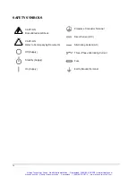
Page 6: ...pply Direct Current DC Alternating Three Phase Fuse Earth Ground Terminal Protective Conductor Terminal Current AC Alternating Current Artisan Scientific Quality Instrumentation Guaranteed 888 88 SOUR...

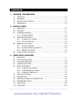
Page 7: ...2 7 2 6 Remote Control Connection 2 7 3 OPERATION OVERVIEW 3 1 Introduction 3 1 3 2 Front Panel Description 3 1 3 3 Rear Panel Description 3 2 3 4 Local Remote Control 3 2 3 5 Modes of Operation 3 3 3...

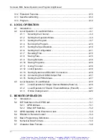
Page 8: ...m and RS 232C Connection 4 16 4 1 14 Connecting the GO NG Output Port 4 17 4 1 15 Setting the GPIB Address 4 17 4 3 Local Operation of Load Module 4 18 4 3 1 Local Operation of Single Channel Module P...

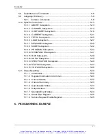
Page 9: ...5 10 12 SHOW Subsystem 5 39 5 10 13 SPECIFICATION Subsystem 5 40 5 10 14 STATUS Subsystem 5 43 5 10 15 VOLTAGE Subsystem 5 48 5 11 Status Reporting 5 50 5 11 1 Introduction 5 50 5 11 2 Register Inform...

Page 10: ...Artisan Scientific Quality Instrumentation Guaranteed 888 88 SOURCE www artisan scientific com Artisan Technology Group Quality Instrumentation Guaranteed 888 88 SOURCE www artisantg com...

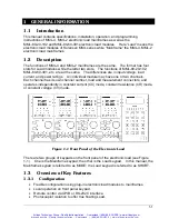
Page 11: ...l has its own channel number load and measurement connectors and operates independently in constant current CC mode constant resistance CR mode or constant voltage CV mode Figure 1 1 Front Panel of th...

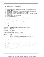
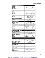
Page 12: ...gnals for each channel 1 4 Specifications Mainframe MML 4 AC input 115 230 switchable or 100 200 switchable Vac line Fuse 5A 250V Amplitude 10 Frequency 47 to 63 Hz Maximum VA 180VA Trigger output Vlo...

Page 13: ...0 32mA S 3 2mA S Current 0 2A 0 20A Resolution 0 5mA 5mA Current Accuracy 0 4 F S MEASUREMENT SECTION VOLTAGE READ BACK Range 0 16V 0 80V Resolution 0 5mV 2 5mV Accuracy 0 05 0 05 F S CURRENT READ BA...

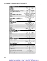
Page 14: ...5A S Resolution 0 001A S 0 01A S Current 0 6A 0 60A Resolution 1 5mA 15mA Current Accuracy 0 4 F S MEASUREMENT SECTION VOLTAGE READ BACK Range 0 16V 0 80V Resolution 0 5mV 2 5mV Accuracy 0 05 0 05 F S...

Page 15: ...n 0 002A S 0 02A S Current 0 12A 0 120A Resolution 3mA 30mA Current Accuracy 0 4 F S MEASUREMENT SECTION VOLTAGE READ BACK Range 0 16V 0 80V Resolution 0 5mV 2 5mV Accuracy 0 05 0 05 F S CURRENT READ...

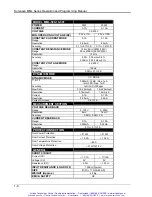
Page 16: ...0mA S Resolution 0 16mA S 1 6mA S Current 0 1A 0 10A Resolution 0 25mA 2 5mA Current Accuracy 0 4 F S MEASUREMENT SECTION VOLTAGE READ BACK Range 0 125V 0 500V Resolution 4mV 16mV Accuracy 0 05 0 05 F...

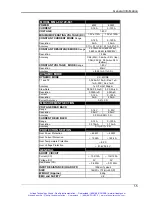
Page 17: ...0 32mA S 3 2mA S Current 0 2A 0 20A Resolution 0 5mA 5mA Current Accuracy 0 4 F S MEASUREMENT SECTION VOLTAGE READ BACK Range 0 125V 0 500V Resolution 4mV 16mV Accuracy 0 05 0 05 F S CURRENT READ BACK...

Page 18: ...tall modules Avoid touching the connector and the circuit board The Sorensen MML 4 Mainframe can accommodate four single width Loads MML 80 20 102 MML 80 60 301 or two double width Loads MML 80 120 60...

Page 19: ...nnel 1 and 2 are always on the farthest left slot of the Mainframe and channel 7 and 8 on the farthest right The channel number is fixed for Mainframe even Load module is empty Figure 2 2 shows the ch...

Page 20: ...l above the unit to ensure adequate air circulation A 1U EIA standard panel is sufficient 2 4 1 Changing Line Voltage The electronic Load can operate with a 115 230 Vac input as indicated on the rear...

Page 21: ...ODULE CHANNEL SCANing The LCD displays the GPIB address in power on condition The GPIB address switch is on the rear panel if the GPIB card is installed If the GPIB card is not installed the LCD will...

Page 22: ...e size length and polarity The minimum wire size required to prevent overheating may not be enough to maintain good regulation The wires should be large enough to limit the voltage drop to no more tha...

Page 23: ...se it will measure at Load terminals Remote sensing compensates for voltage drop in applications that require long lead lengths It is useful when a module is operating in CV or CR mode or when it need...

Page 24: ...ons 2 6 Remote Control Connection The remote operation of Load can be done through GPIB or RS 232C These connectors on the rear panel connect the Load to the controller or computer The GPIB interface...

Page 25: ...CC constant resistance CR and constant voltage CV modes An individual module may have one or two channels Each of them has its own channel number contains its own input connectors and can be turned o...

Page 26: ...on as the Mainframe receives a command via GPIB or RS 232C With remote control in effect only the computer can control the Load The front panel keypad has no effect except the LCL key You can return t...

Page 27: ...lower limits that would cause an error The Mainframe automatically selects data which are rescaled from the programmed value truncates and checks the high and low boundaries before fitting memory When...

Page 28: ...mode of Load module is active the new setting will immediately change the input at a rate determined by the slew rate setting STATic DYNAmic Functions In CC mode two operation functions STATic DYNAmic...

Page 29: ...e dynamic load is commonly used in the test of UUT s performance under transient loading condition Figure 3 4 shows current waveform of dynamic function CCDL1 4A CCDL2 2A CCDL 1A S CCDL 1A S CCDLT1 10...

Page 30: ...Constant Resistance Mode Figure 3 5 Constant Resistance Mode In CR mode the Load will sink a current linearly propotional to the input voltage in accordance with the programmed resistance There is a...

Page 31: ...load level state to another Slew Rate Rise Fall A S Slew rate in constant resistance mode is programmed in Amps second 3 5 3 Constant Voltage Mode Figure 3 6 Constant Voltage Mode In CV mode the Load...

Page 32: ...all the small signal bandwidth of Load will limit the minimum transition time for all programmable slew rates Because of the limit the actual transition time is longer than the expected time based on...

Page 33: ...rent Von Non Latch Figure 3 8 Stop Sinking Current Von Non Latch Artisan Scientific Quality Instrumentation Guaranteed 888 88 SOURCE www artisan scientific com Artisan Technology Group Quality Instrum...

Page 34: ...the short circuit does not affect the programmed setting and Load input will return to the previously programmed values when the short circuit is turned off Note that turning on the short circuit may...

Page 35: ...Load has an overtemperature protection circuit that will turn off the load if the internal temperature exceeds a safe limit The overtemperature OT and temperature error TE status register bits are set...

Page 36: ...rams and power on status DEFAULT can be saved in the EEPROM using SAVE key Later you can recall the settings from the specified file using RECALL key The SAVE and RECALL keys affect all channels simul...

Page 37: ...setting the display will blink setting and let you know that the active setting is to be edited or selected In the remote state the keys on the front panel will have no effect Only the remote controll...

Page 38: ...ngs from specified files 1 to 101 Recalling file 101 means to recall the factory default settings Recalling program is from PROG number 1 to 10 SAVE To save all of the present mode settings of all cha...

Page 39: ...display will show DUMMY CHANNEL When you press CHAN the channel number you want to select will automatically increase to the next existing channel The mainframe will scan the module type at power on a...

Page 40: ...ct Range Function Press MODE use the or v key to select CCL then press ENTER CCL static low range CCDL dynamic low range CCH static high range CCDH dynamic high range MODE SELECT CCL 2 Set Current Lev...

Page 41: ...ohms The slew rate is in A S The following examples illustrate how to set CR values of Load module for model MML 80 60 301 1 Select Range Press MODE and use the and v key to select CRL then press ENTE...

Page 42: ...TER key MODE SELECT CV 2 Set Voltage Level There are 4000 discrete steps from 0 to full scale in each range Set the main voltage level1 A to 5 volts by pressing 5 ENTER Set the level2 B voltage level...

Page 43: ...nce No 1 2 3 4 5 6 7 8 9 10 Corresponding File No 1 2 3 4 5 6 7 8 9 10 Program 2 Sequence No 1 2 3 4 5 6 7 8 9 10 Corresponding File No 11 12 13 14 15 16 17 18 19 20 Program 10 Sequence No 1 2 3 4 5 6...

Page 44: ...Program chain function can chain itself for loop test or chain other programs Press 1 then ENTER to set chain itself for loop test The default setting is 0 PROGRAM CHAIN No 1 3 Setting the Sequence P...

Page 45: ...t ten sequence settings for one program The default setting is SKIP SEQ 1 SKIP 0 AUTO 1 MANUAL 2 6 Setting the Short Channel When the sequence mode is not SKIP you must set the short channel and time...

Page 46: ...on 1 2 3 10 appears in the display to indicate the failed sequence numbers The failed sequences are the results of all failed channels The LED of the failed channel will be illuminated In the test by...

Page 47: ...powerful features use the configuration setup procedures to set the parameters relevant to your application needs This procedure is only needed for initial setup of a test operation The configuration...

Page 48: ...4 4 and 4 5 show Von LATCH ON and OFF current waveform separately Von LATCH 1 ON 2 OFF CAUTION Do not set Von to 0V This will cause an overshoot spike because the Load circuit will be ON regardless o...

Page 49: ...e digit of the four digits displayed No sign is displayed when you select PLUS The default setting is PLUS SIGN OF VOLT 1 PLUS 2 MINUS Set the specifications of entry mode The specifications of the Lo...

Page 50: ...AUTO LOADON mode setting The default setting of AUTO LOADON is OFF AUTO LOADON 1 ON 2 OFF Select the load on mode of module if AUTO LOADON is ON If LOAD is selected the Load module will be active as D...

Page 51: ...led the display will go to the mode editor for you to edit or view the file When you press RECALL the display will show the file number last recalled The default file number is 2 when the mainframe is...

Page 52: ...re locked no settings can change The operation of ON OFF and SPEC keys will not be affected by lock function Press SHIFT and simultaneously to enable disable lock function This is a toggle key to enab...

Page 53: ...r SPEC OFF L FAIL 3 2 H PASS or SPEC OFF L FAIL 5 3 H PASS or SPEC OFF L FAIL 7 4 H PASS or SPEC OFF L FAIL 9 5 H PASS or SPEC OFF L FAIL 11 6 H PASS or SPEC OFF L FAIL 13 7 H PASS or SPEC OFF L FAIL...

Page 54: ...hannel Module Panel A c 7 segment LED Display Displays the measurement Voltage and Current Each display has five digits d 7 segment Display Unit Indicators Indicates the 7 segment display measurement...

Page 55: ...Load input is not enabled The LOAD key controls the on off of the Load module input Its LED will be on when the Load input is enabled h Vsense Connectors These two connectors are Vsense measurement i...

Page 56: ...TIC DYNA key Press STATIC DYNA key to select Dynamic function Press this key again to select static function When Dynamic function is selected the LED of DYNA will be active 3 Short the Load Input The...

Page 57: ...e or double channels Each display has five digits d Channel LED Indicators There are two LEDs to indicate the active right and or left channel s of the Load module When the LED of channel R is on the...

Page 58: ...d to select the display of 7 segment LED and the indicators of channel R and or L The R L key can be used to select Fix mode for rotary knob setting too Please refer to 4 3 3 i Vsense Connectors These...

Page 59: ...ynamic Function The static and dynamic function can be selected through the STATIC DYNA key Press this key to select Dynamic function and press again to select static function When Dynamic function is...

Page 60: ...xed Mode In LOADON press the A B key single channel module or the R L key double channel module for at least 2 5 seconds to access this operation mode Now V and I will be displayed in fixed positions...

Page 61: ...GPIB Address Each device connected to the GPIB interface is assigned a unique address to allow communication with the system controller Before programming the electronic load remotely via a GPIB compu...

Page 62: ...0 13 0 1 1 0 1 29 1 1 1 0 1 14 0 1 1 1 0 30 1 1 1 1 0 15 0 1 1 1 1 Table 5 1 GPIB Addresses 5 2 2 Other DIP Switches The remaining bits on the DIP switch A6 A8 preset the electronic load mainframe to...

Page 63: ...splay is in normal metering mode Pressing the LCL key on the front panel returns the electronic load to local mode Local can be disabled using local lockout so only the controller or the power switch...

Page 64: ...wed by a question mark MEASure VOLTage MEASure CURRent or CHAN Forms of Keywords Every keyword has two forms Long Form The word is spelled out completely to identify its function For instance CURRENT...

Page 65: ...eter 123 12 3 1 23E 3 MIN MAX Table 5 2 Numerical Data Type Numerical data may be followed by a suffix that dimensions the data A suffix may be preceded by a multiplier The MML Series device makes use...

Page 66: ...from the previous command keyword by a space This is shown in examples as a space CURR 3 and on diagrams by the letters SP inside a circle Keyword Separators Keywords or headers are separated by a col...

Page 67: ...example you can combine the following two command statements RES RISE 100 nl and RES L1 400 nl to form one command line as follows RES RISE 100 L1 400 nl To return to the root level form you can Ente...

Page 68: ...commands belonging to the same group is given 5 9 1 Common Commands Common commands defined by the IEEE488 2 standard are generic commands and queries The first part of the language dictionary covers...

Page 69: ...etermines which events of the Standard Event Status Event register see ESR are allowed to set the ESB Event Summary Bit of the Status Byte register A 1 in the bit position enables the corresponding ev...

Page 70: ...tem Interface Description This query requests the Electronic Frame MML 4 to identify itself Query Syntax IDN Return Parameters aard Query Example IDN String Information Sorensen Manufacturer MML 4 Mod...

Page 71: ...urns the types of Electronic Frame MML 4 If channel does not exist it returns 0 If channel exists it returns the types such as MML 80 20 102 Query Syntax RDT Return Parameters aard Query Example 80802...

Page 72: ...ple SRE Returns current setting for Service Request Enable STB Read Status Byte Query Type Device Status Description This query reads the Status Byte register Note that the MSS Master Summary Status b...

Page 73: ...Channel Description Sets all electronic loads as OFF Syntax ABORt 5 10 2 CHANNEL Subsystem CHANnel SP NRf LOAD MIN MAX SP SYNCon SP SP ON 1 OFF 0 ACTive ON 1 OFF 0 ID NR1 aard NR1 Artisan Scientific Q...

Page 74: ...ACTive ON Enable the load module The front panel displays the measurement of voltage and current CHANnel ACTive OFF Disable the load module LCD on the front panel displays OFF Parameter ON 1 OFF 0 Ex...

Page 75: ...After going to a module this query requests the module to identify itself Query Syntax ID Return Parameters aard Query Example ID String Information Sorensen Manufacturer 80202 Model 2 x 100W module...

Page 76: ...O SP OFF 0 ON 1 SOUNd OFF 0 ON 1 SP REMote OFF 0 ON 1 SP SAVE LATCh ON 1 OFF 0 SP NR2 NR2 NR1 NR1 NR1 LOAD SP PROGRAM 0 LOAD 1 NR1 MODE LOAD SP UPDATED 1 OLD 0 Artisan Scientific Quality Instrumentati...

Page 77: ...nt range in CC mode Syntax CONFigure VOLTage RANGEe NRf suffix Parameters Value ranges depend on Load Module For details refer to specification Example CONF VOLT RANG 16 Sets full range as Low for exa...

Page 78: ...on Sets if the load module will do Auto Load On during power on Syntax CONFigure AUTO LOAD ON CONFigure AUTO LOAD OFF Parameters ON 1 OFF 0 Example CONF AUTO LOAD ON Starts Auto Load On during power o...

Page 79: ...ry Syntax CONFigure SOUND Return Parameters NR1 Query Example CONF SOUND Returns the control status of the load module s buzzer sound Return Example 0 or 1 CONFigure REMote Type All Channel Descriptio...

Page 80: ...OLD Parameters UPDATED 1 OLD 0 Example CONF LOAD UPDATED Sets the value of LOADON as that changed by the rotary knob CONF LOAD OLD Sets the value of LOADON as the original set value Query Syntax CONFi...

Page 81: ...P NR2 RISE FALL SP NRf MIN MAX suffix L2 L1 SP NR2 DYNamic SP NRf MIN MAX suffix SP NR2 RISE FALL SP NRf MIN MAX suffix SP NR2 T1 T2 Artisan Scientific Quality Instrumentation Guaranteed 888 88 SOURCE...

Page 82: ...tant Current 10A for Static Load L2 CURR STAT L1 MAX Sets Constant Current maximum value for Static Load L1 CURR STAT L2 MIN Sets Constant Current minimum value for Static Load L2 Query Syntax CURRent...

Page 83: ...hannel specific Description Sets Dynamic Load Current during constant current mode Syntax CURRent DYNamic L1 NRf suffix CURRent DYNamic L2 NRf suffix Parameters For valid value range refer to respecti...

Page 84: ...ISE Returns rise slew rate of dynamic load Return Example 2 5 CURRent DYNamic T1 T2 Type Channel specific Description Sets duration parameter T1 or T2 of dynamic load Syntax CURRent DYNamic T1 NRf suf...

Page 85: ...Ch CURRent Type Channel specific Description Returns real time current measured at the input of the load module Query Syntax FETCh CURRent Return Parameters NR2 Unit Amper Query Example FETC CURR Retu...

Page 86: ...eturns real time current measured at the input of the all load module Query Syntax FETCh ALLCurrent Return Parameters aard Unit Amper Query Example FETC ALLC Return Example 0 0 0 0 5 12 0 12 0 Bit Pos...

Page 87: ...off Syntax LOAD STATe ON LOAD STATe OFF Parameters ON 1 OFF 0 Example LOAD ON Activates the electronic load LOAD OFF Inactivates the electronic load Query Syntax LOAD STATe Return Parameters NR1 Quer...

Page 88: ...ation state Return Example 1 LOAD SHORt KEY Type Channel specific Description Sets the mode of short key in the electronic load Syntax LOAD SHORt KEY TOGGLE Parameters TOGGLE 1 HOLD 0 Example LOAD SHO...

Page 89: ...Position 15 14 13 12 11 10 9 8 7 6 5 4 3 2 1 0 Condition 0 0 0 0 0 0 0 0 0 0 0 OT RV OP OV OC Bit Weight 16 8 4 2 1 Query Example LOAD PROT Returns status of the electronic load Return Example 0 5 10...

Page 90: ...ASure CURRent Return Parameters NR2 Unit Amper Query Example MEAS CURR Return Example 3 15 MEASure INPut Type Channel specific Description Selects the input port of the electronic load to measure volt...

Page 91: ...annel independent Description Returns voltage measured at the input of the all load module Query Syntax MEASure ALLVoltage Return Parameters aard Unit Voltage Query Example MEAS ALLV Return Example 1...

Page 92: ...e of low range MODE CCDH Sets CC dynamic mode of high range MODE CRL Sets CR mode of low range MODE CRH Sets CR mode of high range MODE CV Sets CV mode Parameters CCL CCH CCDL CCDH CRL CRH CV Example...

Page 93: ...E suffix MAX MIN SP OFFTime SP NRf suffix MAX MIN SP NR2 NR2 NR1 NR1 CHAR CHAin SP NRf NR1 NR1 RUN ON 1 OFF 0 SP SHORt CHANnel TIME SP NRf SP NRf NR1 NR2 Artisan Scientific Quality Instrumentation Gua...

Page 94: ...EQ3 Query Syntax PROGram SEQuency Return Parameters NR1 Query Example PROG SEQ Return Example 3 PROGram SEQuency MODE Type By program file Description Sets the type of sequency Syntax PROGram SEQuency...

Page 95: ...ile SEQuency Syntax PROGram SEQuency SHORt TIME Parameters 0 30 0 Example PROG SEQ SHOR TIME 10 Query Syntax PROGram SEQuency SHORt TIME Return Parameter NR2 Query Example PROG SEQ SHOR TIME Return Ex...

Page 96: ...r to respective sepcification Example PROG ONT 10 PROG ONT 100mS Query Syntax PROGram ONTime Return Parameters NR2 Unit Sec Query Example PROG ONT Return Example 10 PROGram OFFTime Type By program fil...

Page 97: ...10 10 RESISTANCE Subsystem RESistance SP NRf MIN MAX suffix L2 L1 SP NR2 RISE SP NRf MIN MAX suffix SP NR2 FALL RESistance L1 L2 Type Channel specific Description Sets static resistance level of cons...

Page 98: ...tive slew rate of constant resistance Syntax RESistance RISE NRf suffix RESistance FALL NRf suffix Parameters For valid value range refer to respective specification Example RES RISE 2 5 Sets CR rise...

Page 99: ...ay R SHOW DISPlay LRV SHOW DISPlay LRI Parameters L R LRV LRI Example SHOW DISP L Displays the voltage and current values of channel L SHOW DISP R Displays the voltage and current values of channel R...

Page 100: ...nnel Description Sets the specific entry mode Syntax SPECification UNIT VALUE SPECification UNIT PERCENT Parameters VALUE 1 PERCENT 0 Example SPEC UNIT VALUE SPEC UNIT PERCENT Query Syntax SPECificati...

Page 101: ...0 NG 1 GO SPECification Type All Channel Description Requests GO NG result reference to all channel specification Query Syntax SPECification Query Example SPEC Returns all channel GO NG result Return...

Page 102: ...SPEC CURR L NRf suffix SPEC CURR C NRf suffix Query Syntax SPECification CURR H SPECification CURR L SPECification CURR C Query Example SPEC CURR H Return Parameters NR2 Unit Current Return Example 4...

Page 103: ...NR1 PTRansition CSUMmary ENABle SP NR1 EVENt QUEStionable CONDition ENABle SP NR1 EVENt NTRansition SP NR1 PTRansition Artisan Scientific Quality Instrumentation Guaranteed 888 88 SOURCE www artisan...

Page 104: ...rresponding channel bit of the Channel Summary Event register Syntax STATus CHANnel ENABle Parameters 0 65535 Example STAT CHAN ENABl 24 Query Syntax STATus CHANnel ENABle Return Parameters NR1 Query...

Page 105: ...TRansition Return Example 4 STATus CSUMmary ENABle Type Channel specific Description Masks for selecting which bits in the Channel Event register are allowed to be summed into the CSUM Channel Summary...

Page 106: ...ion Type Channel specific Description Real time recording of Questionable data Query Syntax STATus QUEStionable CONDition Return Parameters NR1 Query Example STAT QUES COND Returns the channel status...

Page 107: ...ansition Type Channel specific Description Programmable filters determine what type of transition 0 to 1 or 1 to 0 in the Condition register will set the corresponding bit of the Event register Syntax...

Page 108: ...Parameters For valid value range refer to respective specification Example VOLT L1 8V Sets voltage of load L1 as 8V VOLT L2 24V Sets voltage of load L2 as 24V VOLT L1 MAX Sets voltage of load L1 as t...

Page 109: ...nstant voltage mode VOLT CURR MIN Sets loading current limit as the minimum value during constant voltage mode Query Syntax VOLTage CURRent Return Parameters NR2 Unit Amper Query Example VOLT CURR Ret...

Page 110: ...affect the contents of this register PTR NTR Filter Event Register The Event register captures changes in conditions corresponding to condition bits in a condition register or to a specific condition...

Page 111: ...PTR NTR EVENT ENABLE 1 2 4 8 16 LOGICAL OR CE 0 TE 4 OV 1 RV 3 PE 2 1 2 4 8 16 1 2 4 8 16 OPC N U QYE EXE N U CME DDE N U LOGICAL OR 1 4 8 16 32 1 4 8 16 32 STANDARD EVENT STATUS EVENT N U N U CSUM MA...

Page 112: ...ntil the channel has cooled down well below the overtemperature trip point and LOAD PROT CLE is programmed Table 5 5 Bit Description of Channel Status 5 11 3 Channel Status The Channel Status register...

Page 113: ...as the channel status conditions Refer to Table 5 5 for a complete description When the corresponding bit of the Questionable Status Condition register is set the indicated condition is true Program...

Page 114: ...s Byte register Mnemonic Bit Value Meaning OPC 0 1 Operation Complete This event bit is a response to the OPC command It indicates that the device has completed all selected pending operations QYE 2 4...

Page 115: ...f an enabled channel event has occurred It is affected by Channel Condition Channel Event and Channel Summary Event registers QUES 3 8 Questionable Indicates if an enabled questionable event has occur...

Page 116: ...pad char cardName MTA TA pad MLA LA pad if bd ibfind cardName 0 puts GPIB Card Found Error exit 1 if ibpad bd pad ERR puts GPIB Card Address Assignment Error exit 3 ibtmo bd 10 ibsic bd ibsre bd 1 sta...

Page 117: ...s on the screen of PC Niwrite 8 MODE CCL Sets CHANNEL 1 MODE as CCL Niwrite 8 CURR STATIV L1 1 Sets L1 current of CCL as 1A Niread 8 LOAD ON Starts sinking current Niread 8 MEAS VOLT Measures the read...

Page 118: ...7 3 for CC CR CV calibration equipment setup For manual calibration press LOAD to disable the load module input when you change mode or range and press this key again to enable After calibration turn...

Page 119: ...gure 7 1 Test Setup for CC Mode DMM I POWER SUPPLY ELECTRONIC LOAD DMM V Figure 7 2 Test Setup for CR Mode POWER SUPPLY ELECTRONIC LOAD DMM V Figure 7 3 Test Setup for CV Mode Artisan Scientific Quali...

Page 120: ...LM8 75 Oscilloscope 100MHz Tektronics TDS340 Extender Cable 32 pin ribbon cable Chroma part No 806 31000 DC Power Supply 12V 3A GW3030 FAN 100 CFM FLOWMAX 4715KL 04W B30 DC 12V NOTE The TPA7 TPB7 And...

Page 121: ...minals Press R L and STATIC DYNA simultaneously over one second and the module will go to calibration mode Adjust VRB11 on board L till the module s display is as follows LoFFS offset calibration of l...

Page 122: ...splay mode Remove input terminal s short circuit Voltage measurement adjustment channel L Set channel L of the load module to CRH mode Apply DC source to the input terminals of channel L and set the D...

Page 123: ...justment channel L Select CV mode of channel L and program CV voltage to 76V Set current limit of CV mode to 1A in configuration Set the DC source to 80V 0 1A Adjust VRB2 on board A until DMM V readin...

Page 124: ...reading 3 ohms shunt current 2mA CV mode adjustment channel R Set channel L to CV mode and program CV voltage to 76V Set current limit of CV mode to 1A in configuration Set the DC source to 80V 0 1A A...

Page 125: ...ent adjustment Set the load module to CRH mode Set the DC source to 80V 0 1A Connect DMM to the module s input terminals Adjust VRA9 on board L until the display voltage DMM V reading 0 01V Current of...

Page 126: ...o 1A in configuration Set the DC source to 80V 0 1A Adjust VRA2 on board A until DMM V reading 75 997 to 76 003V 7 6 Calibration Procedures of MML 500 10 301 Reference voltage adjustment Connect DMM t...

Page 127: ...asurement Remove input terminals short circuit 2 Voltage measurement full scale calibration Press LOAD and the module displays 2 FS uL Set the DC source to 125V 0 1A and apply to the load module s inp...

Page 128: ...cale data 3 Current measurement calibration Press LOAD and the module displays 4 FS AL Set the DC source to 5V 2 1A and current shunt range to 2A Press LOAD and the module displays EEEEE FFFFF EEEEE r...

Page 129: ...e s current measurement after calibration Adjust the knob of the module until shunt current HHHHH 1 count Press LOAD and the module displays SAvE Save CCH measurement data 4 Current setting offset cal...

Page 130: ...AvE Save CCH offset data 5 Current setting calibration Set the DC source to 5V 5A and current shunt range to 2A Press LOAD and the module displays 8 FS CCL Press LOAD and the module displays 0 9000 PP...

Page 131: ...tting before calibration RRRRR represents the load module s current setting after calibration Adjust the knob of the module until shunt current RRRRR 1 count Press LOAD and the module displays SAvE Sa...

Page 132: ...0 000 TTTTT 20 000 represents the load module s resistance setting before calibration TTTTT represents the load module s resistance setting after calibration Note Because of the module s display limit...

Page 133: ...on board A DMM to TPA3 on board A Adjust VRA4 on board A until DMM DC 10 2400 0 0005V Reference voltage check Connect DMM to TPA6 on board L DMM to TPA3 on board A Check DMM DC 2 48 to 2 60V Software...

Page 134: ...t full scale calibration Press LOAD and the module displays 2 FS uL Set the DC source to 16V 0 1A and apply DC source to the load module s input terminals Press LOAD and the module displays AAAAA BBBB...

Page 135: ...e data 3 Current measurement calibration Press LOAD and the module displays 4 FS AL Set the DC source to 5V 15A and current shunt range to 20A Press LOAD and the module displays EEEEE FFFFF EEEEE repr...

Page 136: ...djust the knob of the module until shunt current HHHHH 1 count Press LOAD and the module displays SAvE Save CCH measurement data 4 Current setting offset calibration Set the DC source to 5V 20mA and c...

Page 137: ...bration Set the DC source to 5V 15A and current shunt range to 20A Press LOAD and the module displays 8 FS CCL Press LOAD and the module displays 10 800 PPPPP 10 800 represent the load module s curren...

Page 138: ...libration Adjust the knob of the module until shunt current RRRRR 1 count Press LOAD and the module displays SAvE Save CCH setting data 6 CR mode calibration Set the DC source to 1 5V 60A and current...

Page 139: ...5000 TTTTT 2 5000 represents the load module s resistance setting before calibration TTTTT represents the load module s resistance setting after calibration Adjust the knob of the module until DMM V r...

Page 140: ...d A DMM to TPA3 on board A Adjust VRA4 on board A until DMM V 10 2400 0 0005V Reference voltage check Connect DMM to TPA6 on board L DMM to TPA3 on board A Check DMM V 2 48 to 2 60V Software calibrati...

Page 141: ...e current measurement Remove input terminals short circuit 2 Voltage measurement full scale calibration Press LOAD and the module displays 2 FS uL Set the DC source to 125V 0 1A and apply DC source to...

Page 142: ...lays SAvE Save the high range full scale data 2 Current measurement calibration Press LOAD and the module displays 4 FS AL Set the DC source to 5V 2A and current shunt range to 2A Press LOAD and the m...

Page 143: ...nts the load module s current measurement after calibration Adjust the knob of the module until shunt current HHHHH 1 count Press LOAD and the module displays SAvE Save CCH measurement data 3 Current...

Page 144: ...odule until shunt current 0 to 5mA Press LOAD and the module displays SAvE Save CCH offset data 4 Current setting calibration Set the DC source to 5V 2A and current shunt range to 2A Press LOAD and th...

Page 145: ...Press LOAD and the module displays 18 000 RRRRR 18 000 represents the load module s current setting before calibration RRRRR represents the load module s current setting after calibration Adjust the k...

Page 146: ...urrent shunt range to 2A Press LOAD and the module displays 10 000 TTTTT 10 000 represents the load module s resistance setting before calibration TTTTT represents the load module s resistance setting...

Page 147: ...tting before calibration UUUUU represents the load module s CV voltage setting after calibration Adjust the knob of the module until DMM V reading UUUUU 1 count Press LOAD and the module displays SAvE...

Page 148: ...e module 2 Remove the two screws securing the module and pull out the module by holding the load connector 3 Place the module on the workbench 4 Remove the eight screws on the top and bottom sides and...

Page 149: ...eration and Programming Manual 7 32 Artisan Scientific Quality Instrumentation Guaranteed 888 88 SOURCE www artisan scientific com Artisan Technology Group Quality Instrumentation Guaranteed 888 88 SO...

Page 150: ...and Technicians on staff in our State of the art Full Service In House Service Center Facility InstraView Remote Inspection Remotely inspect equipment before purchasing with our Innovative InstraView...

Page 151: ...service in house repair center WE BUY USED EQUIPMENT Sell your excess underutilized and idle used equipment We also offer credit for buy backs and trade ins www artisantg com WeBuyEquipment REMOTE IN...

Reviews: