Spectracom TV210G, Instruction Manual
The Spectracom TV210G is a cutting-edge television featuring advanced technology for a superior viewing experience. Ensure optimal performance by downloading the free Instruction Manual from 88.208.23.73:8080, where users can access detailed step-by-step instructions and troubleshooting tips. Enhance your TV experience with the comprehensive manual available for download.
Share
Download


Reviews:
No comments
Related manuals for TV210G

WT-3129Sx1
Brand: La Crosse Technology Pages: 2

Automatic Travel RL705
Brand: LEXIBOOK Pages: 22

RCC 182709
Brand: Biowin Pages: 4

60.2009 Cone Wake-up Light
Brand: TFA Pages: 20

C-0522
Brand: Fadisol Pages: 4

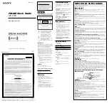
Dream Machine ICF-C180
Brand: Sony Pages: 2

Dream Machine ICF-C180
Brand: Sony Pages: 2

Dream Machine ICF-C160L
Brand: Sony Pages: 2

Dream Machine 3-873-060-34(1)
Brand: Sony Pages: 2

DREAM MACHINE ICF-C1IP
Brand: Sony Pages: 5

DREAM MACHINE 4-115-539-45(1)
Brand: Sony Pages: 2

DREAM MACHINE 3-288-976-11(1)
Brand: Sony Pages: 2
C318 - ICF Clock Radio
Brand: Sony Pages: 2

Dream Machine ICF-C160
Brand: Sony Pages: 5

2-319-815-31(1)
Brand: Sony Pages: 2

CFS-1000L
Brand: Sony Pages: 12

1575422
Brand: Sony Pages: 22

DREAM MACHINE 4-154-584-35(1)
Brand: Sony Pages: 32


