Assembly Instructions
025255R11 Page 1 of 2
Assembly Instructions
Important
Before you begin, read and comply with all safety and operating instructions,
and ensure all parts and correct quantities are included.
Any parts damaged during shipment must be reported within 5 days of receipt.
To report information regarding missing parts or damage, to purchase parts
or accessories, or if you have any questions, please contact us.
www.spectrumfurniture.com
800-235-1262, 715-723-6750
Thank you for purchasing Spectrum products!
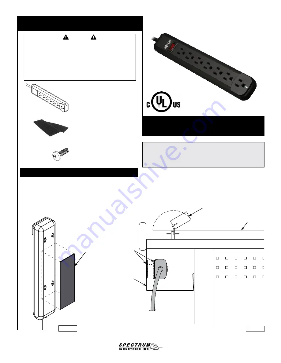
7-Outlet Power Strip
99024
(2) 0100166
6-32 x 1/2” PH Thread-cutting screw
(used when mounting with keyhole
slots on back of power strip)
Power Strip
Hook and
Loop Strips
Cord
Channel
Power
strip
Figure 1A
Hook or
Loop Strip
6” Hook & Loop Strips
(1) 052309 - Hook
(1) 052310 - Loop
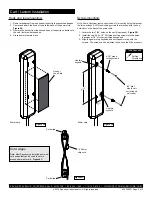
Desk Installation
1. Remove the backer from one hook or loop strip to expose the adhesive.
2. Center and attach the hook or loop to the back of the power strip.
Figure 1A
.
3. Remove the backer from the second hook or loop strip, and attach
to the vertical part of the cord channel shown in
Figure 1B
.
4. Press power strip into place.
Figure 1B
Worksurface
Flip-top section of desk
(your desk may or may
not have this feature)
Side view of desk cord channel
Note: Do not connect any electrical equipment to the power strip until
it is mounted securely. Keep the power strip switched off until plugged
into a wall outlet. To maintain UL-compliance, do not “daisy-chain”
multiple power strips. See instructions included with the power strip for
additional installation, operational, and safety instructions.
(1) 052741
7-Outlet Power Strip


