background image

DXM100 SERIES MANUAL 


118146-001 

Rev A


R


Instruction Manual


High Voltage Power Supply 


MODEL :  


SERIAL# : 


DATE : 


SPELLMAN 
HIGH VOLTAGE ELECTRONICS 
CORPORATION 

475 Wireless Blvd. 
Hauppauge, New York, 11788 
 
+1(631) 630-3000*FAX: +1(631) 435-1620* 
E-mail: 

sales@spellmanhv.com


Website: www.spellmanhv.com 


DXM100 SERIES

Summary of Contents for DXM100 Series

Page 1: ...ction Manual High Voltage Power Supply MODEL SERIAL DATE SPELLMAN HIGH VOLTAGE ELECTRONICS CORPORATION 475 Wireless Blvd Hauppauge New York 11788 1 631 630 3000 FAX 1 631 435 1620 E mail sales spellmanhv com Website www spellmanhv com DXM100 SERIES ...

Page 2: ... aware of the electrical hazards WARNING note in the text call attention to hazards in operation of these units that could lead to possible injury or death CAUTION notes in the text indicate procedures to be followed to avoid possible damage to equipment Copyright 2000 Spellman High Voltage Electronics Corporation All Rights Reserved This information contained in this publication is derived in par...

Page 3: ...spannungsnetzteiles benötigen ca 5 Minuten um sich zu entladen Erden Sie sich nicht und arbeiten Sie nicht in feuchter oder nasser Umgebung Notwendige Reparaturen können es erforderlich machen den Gehäusedeckel während des Betriebes zu entfernen Reparaturen dürfen nur von qualifiziertem eingewiesenem Personal ausgeführt werden WARNING im folgenden Text weist auf gefährliche Operationen hin die zu ...

Page 4: ...de l alimentation Ne vous mettez pas à la masse ou ne travaillez pas sous conditions mouillées ou humides La maintenance peut nécessiter l enlèvement du couvercle lorsque l alimentation est encore allumée Les réparations doivent être effectuées par une personne qualifiée et connaissant les risques électriques Dans le manuel les notes marquées WARNING attire l attention sur les risques lors de la m...

Page 5: ...carica della capacità interna dell alimentatore ad alta tensione Non mettere a terra il proprio corpo oppure operare in ambienti bagnati o saturi d umidità SICUREZZA NELLA MANUTENZIONE Manutenzione potrebbe essere richiesta rimuovendo la copertura con apparecchio acceso La manutenzione deve essere svolta da personale qualificato coscio dei rischi elettrici Attenzione alle AVVERTENZE contenute nel ...

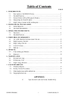
Page 6: ...ONS 3 1 Operation 6 3 2 Standard Features 7 4 PRINCIPLES OF OPERATION 4 1 AC to DC Rectifier and Associated Circuits 13 4 2 High Frequency Inverter 13 4 3 High Voltage Circuits 13 4 4 Control Circuits 14 4 5 Options 14 5 OPTIONS 5 7 Custom Designed Models 15 5 8 Filament 15 6 MAINTENANCE 6 1 Periodic Servicing 16 6 2 Performance Test 16 6 3 High Voltage Dividers 16 7 FACTORY SERVICE 7 1 Warranty R...

Page 7: ...neration for safety purposes LOCAL Operating Features 1 Output Control Voltage current filament limit and preheat level are externally programmable over the entire range from zero to maximum rating via 0 10VDC input 2 10VDC Reference A 10VDC reference is provided for local programming via two potentiometers to be used to adjust filament limit and preheat level 3 High Voltage Enable A hardware base...

Page 8: ... maintain regulation and will result in shutdown of the HV This fault will occur if the output voltage less than 10 below the program value This fault is indicated by illumination of under voltage led status on the front cover and via RS 232 USB or Ethernet as under voltage UNDER CURENT Indicates failure in the current regulation circuitry This fault occurs when the allowable percentage of error b...

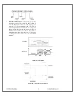
Page 9: ...output power exceeds 105 of programmed value This fault is indicated by illumination of both the over voltage and under voltage led status on the front cover and via RS 232 USB or Ethernet as Power limit This is maximum power limit that can be set 0 1200 watts via the digital interface This value is stored in HVPS memory Figure 1 1 LED Legend DXM100 NEGATIVE POLARITY ...

Page 10: ...d accompanying the unit Standard DXM100 high voltage power supplies and components are covered by warranty Custom and special order models with an X suffix in the model number are also covered by warranty 2 2 Mechanical Installation The DXM100 series module power supplies are designed for installation into existing or newly developed OEM equipment The power supply can also easily fit into bench to...

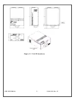
Page 11: ...DXM100 MANUAL 5 118147 001 Rev D Figure 2 1 Unit Dimensions ...

Page 12: ...d to the power supply chassis Using a separate external ground at the load is not recommended An IEC 320 connector is provided for connection to the line voltage source A standard line cord is also provided D Hook up Connect control and monitoring connections as described in this manual E For initial turn on program the voltage and current for zero output Connect the enable disable signal to disab...

Page 13: ...he maximum programmed emission current mA at the lowest kV setting to be used Remember filament maximum values are different than the REQUIRED values for emission Setting 10 15 over the needed emission current values provides headroom as well as better trainset response characteristics Always keep the Filament Limit level at or below the manufacturers recommended maximum filament current specifica...

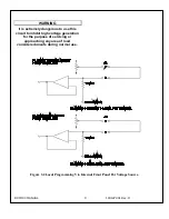
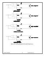
Page 14: ...desired output can be selected See Figure 3 3 for wiring diagram and specifications Local Monitoring Monitor outputs are made available for monitoring the voltage current output and filament preheat level The Monitor outputs are always positive regardless of the output polarity where zero 0 to 10 10 volts equals 0 100 of output See Figure 3 4 for monitoring wiring and see data sheet for pin outs X...

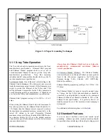
Page 15: ...s extremely dangerous to use this circuit to inhibit high voltage generation for the purpose of servicing or approaching any area of load considered unsafe during normal use Figure 3 2 Local Programming Via Internal Front Panel Pot Voltage Source ...

Page 16: ...DXM100 MANUAL 10 118147 001 Rev D Figure 3 3 Local Programming Via External Voltage Source ...

Page 17: ...DXM100 MANUAL 11 118147 001 Rev D Figure 3 4 Remote Monitoring ...

Page 18: ...DXM100 MANUAL 12 118147 001 Rev D RELAY Figure 3 5 Enable Interlock Logic Control ...

Page 19: ...g with high voltage Do not attempt to approach or touch any internal or external circuits or components that are connected or have been connected to the power supply Be certain to discharge any stored energy that may be present before and after the power supply is used Consult IEEE recommended practices for safety in high voltage testing 510 1983 4 2 High Frequency Inverter The DXM100 is a resonan...

Page 20: ...rol circuitry provides excellent regulation along with outstanding stability performance WARNING LINE VOLTAGE IS PRESENT WHENEVER THE POWER SUPPLY IS CONNECTED TO EXTERNAL LINE VOLTAGES BE SURE TO DISCONNECT THE LINE CORD BEFORE OPENING THE UNIT ALLOW 5 MINUTES FOR INTERNAL CAPACITANCE TO DISCHARGE BEFORE REMOVING ANY COVER 4 5 Options Due to the variations of models and options provided in the DX...

Page 21: ...ation control sheet is added at the end of this instruction manual 5 2 Filament Filament outputs with an emission control loop are available for use with X ray tubes Generally filament outputs are in the range of 3V 10V at currents up to 5A A floating AC filament is provided The filament on a standard DXM100 Module is calibrated to 5a 10V using either a 10ft High Voltage Spellman welcomes the oppo...

Page 22: ...HESE TESTS High voltage test procedures are described in Bulletin STP 783 Standard Test Procedures for High Voltage Power Supplies Copies can be obtained from the Spellman Customer Service Department Test equipment including an oscilloscope a high impedance voltmeter and a high voltage divider such as the Spellman HVD 100 or HVD 200 is needed for performance tests All test components must be rated...

Page 23: ...ed to the customer The Customer shall pay for shipping to and from Spellman A preliminary estimate for repairs will be given by phone by Customer Service A purchase order for this amount is requested upon issuance of the RMA Number A more detailed estimate will be made when the power supply is received at the Spellman Repair Center In the event that repair work is extensive Spellman will call to s...

Page 24: ...To obtain information on Spellman s product warranty please visit our website at http www spellmanhv com en About Warranty aspx ...

Page 25: ...ts Reserved This information contained in this publication is derived in part from proprietary and patent data This information has been prepared for the express purpose of assisting operating and maintenance personnel in the efficient use of the model described herein and publication of this information does not convey any right to reproduce it or to use it for any purpose other than in connectio...

Page 26: ...SB Cabling 8 4 0 Getting Started Software 10 4 1 RS 232 10 4 2 Ethernet 12 4 3 USB 31 5 0 Ethernet Commands 39 5 1 TCP IP Format 39 5 2 Command Arguments 40 5 3 Command Overview 40 5 4 Response Overview 41 5 5 Command Structure 43 6 0 Serial Commands RS 232 USB 73 6 1 Serial Interface Protocol 73 6 2 Command Arguments 73 6 3 Checksums 73 6 4 Command Overview 75 6 5 Response Overview 76 6 6 Command...

Page 27: ...OMPUTER SHOULD BE GROUNDED TO THE SAME GROUND AS THE UUT 1 0 SCOPE This document applies to the communications interfaces on the DXM100 assembly 460188 2 0 FUNCTIONAL DESCRIPTION The DXM100 provides 3 different types of digital communications interfaces RS 232 on J3 Ethernet 10 100 Base T on J5 Universal Serial Bus on J4 3 0 GETTING STARTED INTERFACE WIRING AND PIN OUTS 3 1 RS232 INTERFACE The RS2...

Page 28: ...118142 001 Rev B Page 4 of 104 Figure 1 J3 RS 232 DB 9M pinout front view PIN DESCRIPTION 1 2 Tx Out 3 Rx In 4 5 Ground 6 7 8 9 ...

Page 29: ... connector Network attachment via Crossover and Standard Ethernet cables Supported Operating Systems Windows 98 2ED Windows 2000 SP2 Windows NT SP6 Windows XP Professional Figure 2 J5 Ethernet RJ45 Jack front view PIN DESCRIPTION 1 TX 2 TX 3 RX 4 5 6 RX 7 8 The Ethernet RJ 45 has two LED indicators as shown in Figure 2 The left LED LED1 indicates that the network processor has a valid network link...

Page 30: ...able is used to connect the DXM100 serial port to the serial port on a standard personal computer Please refer to the following chart 3 5 ETHERNET CABLING Shielded Category 5 CAT5 Ethernet patch cables are used to connect the DXM100 to the host computer There are two ways to connect to the DXM100 board via Ethernet the first is to directly cable between the host and the DXM100 board and the second...

Page 31: ...ugh Please refer to the two cable ends shown below in figure 4 Figure 4 Crossover Cable for Direct Connection A standard connection through a hub switch or network uses a standard CAT5 patch cable Please refer to the two cable ends shown below in figure 5 Figure 5 Standard Straight Through Cable Standard CAT5 Patch 1 1 1 1 ...

Page 32: ...MI ENVIRONMENTS If the DXM100 USB interface is being used in a high EMI environment ferrites should be added to the USB cable Figure 7 illustrates the possible combinations of ferrites that can be used to achieve acceptable operation under these conditions P O W E R S U P P L Y W IT H U S B F E R R IT E B E A D c a b le F E R R IT E B E A D c a b le P C W IT H U S B F E R R IT E C O R E c a b le F...

Page 33: ...led In extreme cases ferrite cores may be added where the cable is looped 3 or 4 times around the core as shown in figure 8 Cores of 1 5 to 2 inches should be used at both ends of the cable Figure 8 Example of a USB Cable Using Ferrites Please refer to the USB Interface Setup section for an explanation of how USB works and why EMI may present a problem for this communications interface ...

Page 34: ...in the unit 4 1 1 Enabling Communications Objects in Visual Basic for RS 232 Communications in Microsoft Visual Basic 6 0 are directed to a control that abstracts the port In the case of serial and USB we need Microsoft Comm Control 6 0 To enable this in your VB 6 project go to Project Components Then in the list make sure that Microsoft Comm Control 6 0 has a check next to it The Comm Control Obj...

Page 35: ...e 11 of 104 For the Default scenario include the following commands in the Form_Load routine MSComm1 CommPort portNumber MSComm1 PortOpen True For the Choice scenario place the above two commands in a selectable menu item ...

Page 36: ... Supply and allows the unit to be configured in real time The application consists of three web pages a page displaying contact information a license agreement and a monitoring and control applet that is at the heart of this application The Web Server application for the DXM100 is presented as an example in the following pages 4 2 2 Web Pages 4 2 2 1 Web Page 1 Contact Information Page Figure 9 di...

Page 37: ...118142 001 Rev B Page 13 of 104 Figure 9 Web Page 1 Contact Information ...

Page 38: ... Web Page 2 License Agreement Page Figure 10 displays the license agreement Here the user can either agree or disagree with the Spellman license agreement Click on I Accept to continue on to the applet Figure 10 Web Page 2 License Agreement ...

Page 39: ... a browser that requires an Internet browser with an installed JVM Java Virtual Machine The Default username and password for the applet is Username admin Password SHV_Applet We have tested under Internet Explorer 5 and 6 Microsoft JVM 5 and Sun JVM versions 1 4 1 and 1 4 2 4 2 2 3 2 Description of Monitor and Control Applet Figure 11 displays an example of an embedded monitor and control applicat...

Page 40: ...alue or real world value which is the field the user is going to use most of the time The bottom field is the raw digital to analog converter DAC value that is actually sent to the DXM100 Enter either the desired set point level in the top field or the DAC value between 0 and 4095 in the bottom field The user can then click Apply to send the set point to the DXM100 and remain in the set point scre...

Page 41: ...3 Settings Pop up Menus Notice that there are three choices The first Network Settings refers to the network settings for the network component of the DXM100 and not the Monitor and Control applet The second option Poll Rate affects refresh rate of the Monitor and Control Applet and will be discussed in the next section In the about choice firmware version information is displayed both for the Mon...

Page 42: ... refresh quicker However setting it too low may cause requests to queue up in the send queue This may make controlling the DXM100 very slow as control requests now must wait behind queued status requests We recommend leaving the delay set at the default value 4 2 2 8 Version Information Figure 15 Version Information ...

Page 43: ...eing received by the applet from the DXM100 The next state is No Data Received which is when there is still a valid connection but no responses have been received from the DXM100 for 2 seconds Lastly the text field displays Disconnected when the TCP IP session has been disconnected To operate the UUT using the Computer interface the UUT must be set to Remote Mode by Clicking Click to Set Remote Wh...

Page 44: ...tion As mentioned above both the IP Address and Subnet Mask need to be configured In our environment computers normally are assigned IP addresses dynamically using DHCP We need to change this and assign the IP Address statically to the one we have selected Here are the steps on Windows XP On the desktop right click on My Network Places and select properties at the bottom of the menu Figure 16 Righ...

Page 45: ... selecting properties you are brought up to the screen below Figure 18 You must RIGHT CLICK and select Properties on Local Area Connection and not double click which will display a window similar to figure 19 Figure 18 Here you must Right Click and Select Properties ...

Page 46: ... select Internet Protocol TCP IP and click on the Properties button to be brought to figure 20 Lastly you must disable any firewall software you have running If you are running a proxy server for Internet access you must also disable the proxy client Disabling this also requires a reboot ...

Page 47: ... command line tool so we will need to bring up a command prompt Under Windows NT 2000 and XP the name of this command is CMD Under Windows 98 the name of this command is Command To do this click on Start Run Cmd Then on the command line type Ping IP Address For example Ping 192 168 1 4 If the DXM100 is found at the specified IP address the Ping command will respond with a report that is similar to...

Page 48: ...ing the DXM100 For a Local Area Network LAN If you have chosen to place the DXM100 onto your local area network you will need A CAT5 network patch cable to physically connect the DXM100 to the LAN A static IP address to assign to the DXM100 Remember that even if the IP address you have selected is in general a valid IP address it needs to be valid for your LAN local area network Otherwise the devi...

Page 49: ...new instance of the applet to monitor and control the DXM100 after reconfiguring it This may also require reconfiguring the host computer with the correct host IP address subnet mask and TCP port The device name does not affect the operation of the DXM100 it is simply a way for the user to differentiate multiple units on the same network Depending on the type of network you are attaching the DXM10...

Page 50: ...n Check and record the data in the User Record Table below If the desired change is correct click on the Yes button Clicking on Cancel will cancel any changes made Figure 21 2 Warning Review Screen User Record Table IP Address _______________________________________ Port Address _____________________________________ Subnet Mask _____________________________________ WARNING Port address 50000 is re...

Page 51: ...ev B Page 27 of 104 Figure 21 3 Port Error Selection Screen The TCP IP Status field in the applet window will show Connected No Data Received as shown in Figure 21 4 Figure 21 4 TCP IP Status Field No Data Received ...

Page 52: ...and close out all browser windows on the PC Then open up a browser again and re log in to the changed IP address Note Again please remember the changed parameters as there is no procedure at this time to recover the default parameters 4 2 4 Enabling Communications Objects in Visual Basic for Ethernet Communications For Ethernet communications we need Microsoft Winsock Control 6 0 and SP5 To enable...

Page 53: ...he following commands tcpClient RemoteHost host tcpClient RemotePort portNumber tcpClient Connect For further information regarding the use of the above commands please refer to your Visual Studio Help File 4 2 5 1 Data Output Example MSComm1 is both the serial and USB port TcpClient is the Ethernet port If portType ethernet Then tcpClient SendData str Else MSComm1 InBufferCount 0 On Error GoTo do...

Page 54: ...118142 001 Rev B Page 30 of 104 str str MSComm1 Input End If Loop Until InStr str Chr 3 Or Timer t1 1 If InStr str Chr 3 0 Then tmrOpenClose Enabled False End If End If ...

Page 55: ... driver HID 4 3 1 USB Driver Installation The HID driver is a Windows driver installed with the operating system To determine if the driver had been acquired open the System properties window selecting the Control Panel System Properties Figure 22 System Properties Then select Device Manager and expand the Human Interface Devices View the properties of the USB Human Interface Device icon and verif...

Page 56: ...t the host may lose connection with the client This can cause problems with data transfers over the USB cable The DXM100 when used in combination with the HID Windows driver makes it possible for the host to renumerate the client connection and reestablish communications This is providing the control application implements a method of timeout and retry NOTE If an EMI disruption occurrs the DXM100 ...

Page 57: ...New usbDll Using this statement determines whether a connection is present MyDeviceDetected usb FindTheHid If MyDeviceDetected is true then the connection is present 4 3 5 Software Considerations for USB Reconnection The following Visual Basic code snippets are presented as a guideline for implementation with revision C and higher assemblies 4 3 5 1 Recognize partial corrupt or absent data 1 temp2...

Page 58: ...e Output Routine Notice that on line 13 we register an error handler in case the port is invalid because we have closed it in another routine Notice that on line 16 we start a timer When we output data on the port we start a timer to keep track of incoming data If we get no incoming data it means that communications have been interrupted 1 Private Sub outputOutputString outputString As String 2 Di...

Page 59: ...portType ethernet Then 10 Do 11 DoEvents 12 tcpClient GetData temp 13 str str temp 14 Loop Until InStr str Chr 3 Or Timer t1 1 15 On Error Resume Next 16 ElseIf portType USB Then 17 Do 18 DoEvents 19 stra usb ReadReport 20 str str stra 21 str str ReadReport 22 Loop Until InStr str Asc 3 Or Timer t1 0 09 23 Else 24 Do 25 DoEvents 26 If MSComm1 InBufferCount 0 Then 27 str str MSComm1 Input 28 End If...

Page 60: ...ere we register an error handler 1 Private Sub tmrOpenClose_Timer 2 If MSComm1 PortOpen True Then 3 4 MSComm1 PortOpen False 5 On Error GoTo done 6 MSComm1 PortOpen True 7 done 8 tmrOpenClose Enabled False 9 End If 10 11 End Sub 4 3 5 6 Example Timer Routine Port Reconnection This is another timer routine whose purpose is to turn the port on if it is off Notice that in line 8 an error handler is c...

Page 61: ...but we may not get commas in the correct place Notice that we register an error handler on line 26 so that the mid function which would raise an error when given a negative number is handled 1 Private Sub btn_EMI_Click 2 Dim temp2 3 Dim Response1 4 Dim Response2 5 Dim number 6 Dim Comma 7 Dim CommaPos 8 Dim Start 9 Dim ODATA 10 11 Comma 12 Start 5 13 14 If tmr_RCVTIMER Enabled True Then tmr_RCVTIM...

Page 62: ...t str Response1 0 0004884 0 0 31 32 txt_DACB Text ODATA mA 33 frm_RAWDATA txt_RAWDACB Text str Response1 34 txt_DACB BackColor vbWhite 35 CommStatusFlag True 36 endhere 37 38 If portType ethernet Then 39 tmr_NETRCVTMR Enabled True 40 Else 41 tmr_RCVTIMER Enabled True 42 End If 43 44 If AutoUpdate True Then tmr_UPDATE Enabled True 46 End Sub ...

Page 63: ... Systems Interconnection OSI TCP IP protocol stack specifically the upper 4 layers Byte 0 Protocol Version Header Length Type Of Service Total Length 4 Packet ID Flags Fragmentation Offset 8 Time To Live Protocol Header checksum 12 Source Address 16 Destination Address 20 Source Port Destination Port 24 Sequence Number 28 Acknowledgement Number 32 Data Offset Reserved Code Bits Window 36 Checksum ...

Page 64: ...sed This being the case commands and responses that carry data are variable in length 5 3 COMMAND OVERVIEW Data Byte section of the TCP IP Datagram Command Name CMD ARG RANGE Program RS 232 unit baud rate 07 1 ASCII 1 5 Program kV 10 1 4 ASCII 0 4095 Program mA 11 1 4 ASCII 0 4095 Program Filament Limit 12 1 4 ASCII 0 4095 Program Filament Pre Heat 13 1 4 ASCII 0 4095 Request kV Setpoint 14 None R...

Page 65: ...equest mA monitor 61 None Request Filament Feedback 62 None Request Filament Limit 63 None Request Filament Pre Heat 64 None Request 15V LVPS 65 None Request Faults 68 None Program Local Remote Mode 99 1 ASCII 0 or 1 5 4 RESPONSE OVERVIEW The command responses will follow the same network TCP IP header format as outlined above in section 5 1 This list is comprised of Commands with complex response...

Page 66: ...High Voltage On 21 13 ASCII Request Status 22 11 ASCII Request DSP Software Version 23 17 ASCII Request Hardware Version 24 9 ASCII Request Web Server Version 25 17 ASCII Request Model number 26 11 ASCII Request Power Limit Setpoint 48 7 10 ASCII Request Network Settings 50 48 104 ASCII Read Interlock Status 55 11 ASCII Request kV monitor 60 7 10 ASCII Request mA monitor 61 7 10 ASCII Request Fila...

Page 67: ... kV Description The host requests that the firmware change the setpoint of kV Direction Host to supply Syntax STX 10 ARG ETX Where ARG 0 4095 in ASCII format Example STX 10 4095 ETX Response STX 10 ETX STX 10 ARG ETX where ARG error code Error Codes TBD 1 out of range ...

Page 68: ...tion The host requests that the firmware change the setpoint of mA Direction Host to supply Syntax STX 11 ARG ETX Where ARG 0 4095 in ASCII format Example STX 11 4095 ETX Response STX 11 ETX STX 11 ARG ETX where ARG error code Error Codes TBD 1 out of range ...

Page 69: ...tion The host requests that the firmware change the setpoint of Filament Limit Direction Host to supply Syntax STX 12 ARG ETX Where ARG 0 4095 in ASCII format Example STX 12 4095 ETX Response STX 12 ETX STX 12 ARG ETX where ARG error code Error Codes TBD 1 out of range ...

Page 70: ...tion The host requests that the firmware change the setpoint of Filament Pre Heat Direction Host to supply Syntax STX 13 ARG ETX Where ARG 0 4095 in ASCII format Example STX 13 4095 ETX Response STX 13 ETX STX 13 ARG ETX where ARG error code Error Codes TBD 1 out of range ...

Page 71: ...of 104 5 5 5 Request kV Setpoint Description The host requests that the firmware report the kV setpoint Direction Host to supply Syntax STX 14 ETX Response STX 14 ARG ETX Where ARG 0 4095 in ASCII format Example STX 14 4095 ETX ...

Page 72: ...04 5 5 6 Request mA Setpoint Description The host requests that the firmware report the current mA setpoint Direction Host to supply Syntax STX 15 ETX Response STX 15 ARG ETX Where ARG 0 4095 in ASCII format Example STX 15 4095 ETX ...

Page 73: ...uest Filament Limit Setpoint Description The host requests that the firmware report the current Filament Limit setpoint Direction Host to supply Syntax STX 16 ETX Response STX 16 ARG ETX Where ARG 0 4095 in ASCII format Example STX 16 4095 ETX ...

Page 74: ...t Filament Pre Heat Setpoint Description The host requests that the firmware report the current Filament Pre Heat setpoint Direction Host to supply Syntax STX 17 ETX Response STX 17 ARG ETX Where ARG 0 4095 in ASCII format Example STX 17 4095 ETX ...

Page 75: ...requests that the firmware transmit the present values of Analog Monitor Readbacks Direction Host to supply Syntax STX 19 ETX Example STX 19 ETX Response STX 19 ARG1 ARG2 ARG3 ETX Where ARG1 kV monitor 0 4095 ARG2 mA monitor 0 4095 ARG3 Filament monitor 0 4095 Example STX 19 4095 4095 4095 ETX ...

Page 76: ...iption The host requests that the firmware sends the present value of the Total Hours High Voltage On Direction Host to supply Syntax STX 21 ETX Example STX 21 ETX Response STX 21 ARG1 ARG2 ARG3 ARG4 ARG5 ARG6 ETX Where ASCII 0x2E ARGx 0 9 in ASCII format Example STX 21 99999 9 ETX ...

Page 77: ... STX 22 ARG1 ARG2 ARG3 ARG4 ETX Where ARG1 1 HvOn 0 HvOff ARG2 1 Interlock 1 Open 0 Interlock 1 Closed ARG3 1 Fault Condition 0 No Fault ARG4 1 Remote Mode 0 Local Mode Example STX 22 1 1 0 0 ETX NOTE This response will also be sent in an unsolicited manner when a change of state is detected on the HvOn and Interlock 1 bits This is providing that a valid handle has already been established with a ...

Page 78: ... requests that the firmware sends the DSP firmware version Direction Host to supply Syntax STX 23 ETX Example STX 23 STX Response STX 23 ARG ETX Where ARG consists of eleven ASCII characters representing the current firmware part number version The format is SWM9999 999 Example STX 23 SWM9999 999 ETX ...

Page 79: ...the firmware sends the hardware version Direction Host to supply Syntax STX 24 ETX Example STX 24 ETX Response STX 24 ARG ETX Where ARG consists of 3 ASCII characters representing the hardware version The format is ANN where A is an alpha character and N is a numeric character Example STX 24 A01 ETX ...

Page 80: ...sts that the firmware sends the Web Server firmware part number version Direction Host to supply Syntax STX 25 ETX Example STX 25 ETX Response STX 25 ARG ETX Where ARG consists of eleven ASCII characters representing the current firmware part number version The format is SWM9999 999 Example STX 25 SWM9999 999 ETX ...

Page 81: ...nds the unit model number Direction Host to supply Syntax STX 26 ETX Example STX 26 ETX Response STX 26 ARG ETX Where ARG consists of five ASCII characters representing the model number The format is XNNNN or DXM100NN where N is a numeric character See section 7 0 for model number codes Example STX 25 X9999 ETX ...

Page 82: ...2 001 Rev B Page 58 of 104 5 5 16 Reset Run Hours Description The host requests that the firmware resets the run hour counter Direction Host to supply Syntax STX 30 ETX Example STX 30 ETX Response STX 30 ETX ...

Page 83: ... Rev B Page 59 of 104 5 5 17 Reset Faults Description The host requests that the firmware resets all Fault messages and indicators Direction Host to supply Syntax STX 31 ETX Example STX 31 ETX Response STX 31 ETX ...

Page 84: ...18 Program Power Limit Description The Host sets the power limit of the unit Direction Host to Supply Example STX 47 ARG ETX Where ARG 0 1200 in ASCII format Response STX 47 ETX or STX 47 ARG ETX Where ARG is error Code TBD 1 out of range ...

Page 85: ...Request Power Limit Setpoint Description The host requests that the firmware report the current Power lImit setpoint Direction Host to Supply Syntax STX 48 ETX Response STX 48 ARG ETX Where ARG 0 1200 in ASCII format Example STX 48 1200 ETX ...

Page 86: ... and MAC address is in MAC Address notation ARG1 Device Name 1 character minimum up to 20 maximum ARG2 IP Address nnn nnn nnn nnn where nnn represents a number from 0 to 255 ARG3 Remote Port 5001 or from 49152 to 65535 ARG4 Subnet Mask xxx xxx xxx xxx where xxx represents a number from 0 to 255 ARG5 Default Gateway yyy yyy yyy yyy where yyy represents a number from 0 to 255 ARG6 MACAddress zzz zzz...

Page 87: ... is a decimal number Subnet Mask and Default Gateway are also dotted notation and MAC address is in MAC Address notation ARG1 Device Name 1 character minimum up to 20 maximum ARG2 IP Address nnn nnn nnn nnn where nnn represents a number from 0 to 255 ARG3 Remote Port 5001 or from 49152 to 65535 ARG4 Subnet Mask xxx xxx xxx xxx where xxx represents a number from 0 to 255 ARG5 Default Gateway yyy yy...

Page 88: ...tatus Description The host requests that the firmware read the status of the interlock channel Direction Host to supply Syntax STX 55 ETX Response STX 55 ARG1 ETX Where ARG1 is Interlocks 1 A 1 indicates that the Interlock is energized Example STX 55 1 ETX ...

Page 89: ...3 Request kV Monitor Description The host requests that the firmware report kV monitor Direction Host to supply Syntax STX 60 ETX Response STX 60 ARG ETX Where ARG 0 4095 in ASCII format representing unscaled value Example STX 60 4095 ETX ...

Page 90: ...4 Request mA Monitor Description The host requests that the firmware report mA monitor Direction Host to supply Syntax STX 61 ETX Response STX 61 ARG ETX Where ARG 0 4095 in ASCII format representing unscaled value Example STX 61 4095 ETX ...

Page 91: ...st Filament Feedback Description The host requests that the firmware report Filament Feedback Direction Host to supply Syntax STX 62 ETX Response STX 62 ARG ETX Where ARG 0 4095 in ASCII format representing unscaled value Example STX 62 4095 ETX ...

Page 92: ... 26 Request 15V LVPS Description The host requests that the firmware report 15V LVPS Direction Host to supply Syntax STX 65 ETX Response STX 65 ARG ETX Where ARG 0 4095 in ASCII format representing unscaled value Example STX 65 4095 ETX ...

Page 93: ...rt Faults Direction Host to supply Syntax STX 68 ETX Response STX 68 ARG1 ARG2 ARG3 ARG4 ARG5 ARG6 ARG7 ETX Where ARGx 1 Fault 0 No Fault in ASCII format ARG1 ARC ARG2 Over Temperature ARG3 Over Voltage ARG4 Under Voltage ARG5 Over Current ARG6 Under Current ARG7 Power Limit Example STX 68 0 0 0 0 1 0 0 ETX ...

Page 94: ... host requests that the firmware turn high voltage on or high voltage off Direction Host to supply Syntax STX 98 ARG ETX Where ARG 1 HV on 0 HV off in ASCII format Example STX 98 1 ETX Response STX 98 ETX STX 98 ARG ETX where ARG error code Error Codes TBD 1 out of range ...

Page 95: ...on The host requests that the firmware to switch between Local and Remote Mode Direction Host to supply Syntax STX 99 ARG ETX Where ARG 1 Remote 0 Local in ASCII format Example STX 99 1 ETX Response STX 99 ETX STX 99 ARG ETX where ARG error code Error Codes TBD 1 out of range ...

Page 96: ...e for RS 232 Direction Host to supply Syntax STX 07 ARG CSUM ETX Where ARG 1 9 6k in ASCII format ARG 2 19 2k in ASCII format ARG 3 38 4k in ASCII format ARG 4 57 6k in ASCII format ARG 5 15 2k in ASCII format Example STX 07 1 CSUM ETX Response STX 07 CSUM ETX STX 07 ARG CSUM ETX where ARG error code Error Codes TBD 1 out of range ...

Page 97: ...h 6 3 CHECKSUMS The checksum is computed as follows Add the CMD and ARG bytes into a 16 bit or larger word The bytes are added as unsigned integers Take the 2 s compliment negate it Truncate the result down to the eight least significant bits Clear the most significant bit bit 7 of the resultant byte bitwise AND with 0x7F Set the next most significant bit bit 6 of the resultant byte bitwise OR wit...

Page 98: ...er Dim CSb2 As Integer Dim CSb3 As Integer Dim CSb Dim X X 0 For i 1 To Len outputString Starting with the CMD character X X Asc Mid outputString i 1 adds ascii values together Next i CSb1 256 X CSb2 127 And CSb1 Twos Complement CSb3 64 Or CSb2 OR 0x40 CSb Chr Val H Hex CSb3 ProcessOutputString Chr 2 outputString CSb Chr 3 End Function ...

Page 99: ... 14 None Request mA Setpoint 15 None Request Filament Limit Setpoint 16 None Request Filament Pre Heat Setpoint 17 None Request Analog Monitor Readbacks 19 None Request HV On Hours Counter 21 None Request Status 22 None Request Software Version 23 None Request Hardware Version 24 None Request Web Server Version 25 None Request Model Number 26 None Reset HV On Hours Counter 30 None Reset Faults 31 ...

Page 100: ... This list is comprised of Commands with complex responses only Commands using a simple response will use the character ASCII 0x24 as a Success response or a single character error code These responses will be eight ASCII characters in length Response Name CMD Response Request kV Setpoint 14 10 ASCII Request mA Setpoint 15 10 ASCII Request Filament Limit Setpoint 16 10 ASCII Request Filament Pre H...

Page 101: ...quest Model number 26 11 ASCII Request Power Limit Setpoint 48 7 10 ASCII Request Network Settings 50 48 104 ASCII Read Interlock Status 55 11 ASCII Request kV monitor 60 7 10 ASCII Request mA monitor 61 7 10 ASCII Request Filament Feedback 62 7 10 ASCII Request 15V LVPS 65 7 10 ASCII Request Faults 68 7 ASCII ...

Page 102: ...ption The host requests that the firmware change the setpoint of kV Direction Host to supply Syntax STX 10 ARG CSUM ETX Where ARG 0 4095 in ASCII format Example STX 10 4095 CSUM ETX Response STX 10 CSUM ETX STX 10 ARG CSUM ETX where ARG error code Error Codes TBD 1 out of range ...

Page 103: ...ost requests that the firmware change the setpoint of mA Direction Host to supply Syntax STX 11 ARG CSUM ETX Where ARG 0 4095 in ASCII format Example STX 11 4095 CSUM ETX Response STX 11 CSUM ETX STX 11 ARG CSUM ETX where ARG error code Error Codes TBD 1 out of range ...

Page 104: ...t the firmware change the setpoint of Filament Limit Direction Host to supply Syntax STX 12 ARG CSUM ETX Where ARG 0 4095 in ASCII format Example STX 12 4095 CSUM ETX Response STX 12 CSUM ETX STX 12 ARG CSUM ETX where ARG error code Error Codes TBD 1 out of range Standard Scaling 0 4095 0 5 amps ...

Page 105: ... the firmware change the setpoint of Filament Pre Heat Direction Host to supply Syntax STX 13 ARG CSUM ETX Where ARG 0 4095 in ASCII format Example STX 13 4095 CSUM ETX Response STX 13 CSUM ETX STX 13 ARG CSUM ETX where ARG error code Error Codes TBD 1 out of range Standard Scaling 0 4095 0 2 5 amps ...

Page 106: ... 6 5 Request kV Setpoint Description The host requests that the firmware report the kV setpoint Direction Host to supply Syntax STX 14 CSUM ETX Response STX 14 ARG CSUM ETX Where ARG 0 4095 in ASCII format Example STX 14 4095 CSUM ETX ...

Page 107: ... Request mA Setpoint Description The host requests that the firmware report the current mA setpoint Direction Host to supply Syntax STX 15 CSUM ETX Response STX 15 ARG CSUM ETX Where ARG 0 4095 in ASCII format Example STX 15 4095 CSUM ETX ...

Page 108: ...ament Limit Setpoint Description The host requests that the firmware report the current Filament Limit setpoint Direction Host to supply Syntax STX 16 CSUM ETX Response STX 16 ARG CSUM ETX Where ARG 0 4095 in ASCII format Example STX 16 4095 CSUM ETX ...

Page 109: ...nt Pre Heat Setpoint Description The host requests that the firmware report the current Filament Pre Heat setpoint Direction Host to supply Syntax STX 17 CSUM ETX Response STX 17 ARG CSUM ETX Where ARG 0 4095 in ASCII format Example STX 17 4095 CSUM ETX ...

Page 110: ...host requests that the firmware sends the present value of the Total Hours High Voltage On Direction Host to supply Syntax STX 21 CSUM ETX Example STX 21 CSUM ETX Response STX 21 ARG1 ARG2 ARG3 ARG4 ARG5 ARG6 CSUM ETX Where ASCII 0x2E ARGx 0 9 in ASCII format Example STX 21 99999 9 CSUM ETX ...

Page 111: ...UM ETX Example STX 22 CSUM ETX Response STX 22 ARG1 ARG2 ARG3 ARG4 CSUM ETX Where ARG1 1 HvOn 0 HvOff ARG2 1 Interlock 1 Open 0 Interlock 1 Closed ARG3 1 Fault Condition 0 No Fault ARG4 1 Remote Mode 0 Local Mode Example STX 22 1 1 0 0 CSUM ETX NOTE This response will also be sent in an unsolicited manner when a change of state is detected on the HvOn and Interlock 1 bits ...

Page 112: ...that the firmware sends the DSP firmware version Direction Host to supply Syntax STX 23 CSUM ETX Example STX 23 CSUM STX Response STX 23 ARG CSUM ETX Where ARG consists of eleven ASCII characters representing the current firmware part number version The format is SWM9999 999 Example STX 23 SWM9999 999 CSUM ETX ...

Page 113: ...re sends the hardware version Direction Host to supply Syntax STX 24 CSUM ETX Example STX 24 CSUM ETX Response STX 24 ARG CSUM ETX Where ARG consists of 3 ASCII characters representing the hardware version The format is ANN where A is an alpha character and N is a numeric character Example STX 24 A01 CSUM ETX ...

Page 114: ...he firmware sends the Web Server firmware part number version Direction Host to supply Syntax STX 25 CSUM ETX Example STX 25 CSUM ETX Response STX 25 ARG CSUM ETX Where ARG consists of eleven ASCII characters representing the current firmware part number version The format is SWM9999 999 Example STX 25 SWM9999 999 CSUM ETX ...

Page 115: ...it model number Direction Host to supply Syntax STX 26 CSUM ETX Example STX 26 CSUM ETX Response STX 26 ARG CSUM ETX Where ARG consists of five ASCII characters representing the model number The format is XNNNN or DXM100NN where N is a numeric character See section 7 0 for model number codes Example STX 25 X9999 CSUM ETX ...

Page 116: ...v B Page 92 of 104 6 6 15 Reset Run Hours Description The host requests that the firmware resets the run hour counter Direction Host to supply Syntax STX 30 CSUM ETX Example STX 30 CSUM ETX Response STX 30 CSUM ETX ...

Page 117: ...Page 93 of 104 6 6 16Reset Faults Description The host requests that the firmware resets all Fault messages and indicators Direction Host to supply Syntax STX 31 CSUM ETX Example STX 31 CSUM ETX Response STX 31 CSUM ETX ...

Page 118: ...ogram Power Limit Description The Host sets the power limit of the unit Direction Host to Supply Example STX 47 ARG CS ETX Where ARG 0 1200 in ASCII format Response STX 47 CS ETX or STX 47 ARG CS ETX Where ARF is error Code TBD 1 out of range ...

Page 119: ...est Power Limit Setpoint Description The host requests that the firmware report the current Power limit setpoint Direction Host to Supply Syntax STX 48 CS ETX Response STX 48 ARG CS ETX Where ARG 0 1200 in ASCII format Example STX 48 1200 CS ETX ...

Page 120: ...escription The host requests that the firmware read the status of the interlock channel Direction Host to supply Syntax STX 55 CSUM ETX Response STX 55 ARG1 CSUM ETX Where ARG1 is Interlocks 1 A 1 indicates that the Interlock is energized Example STX 55 1 CSUM ETX ...

Page 121: ...st kV Monitor Description The host requests that the firmware report kV monitor Direction Host to supply Syntax STX 60 CSUM ETX Response STX 60 ARG CSUM ETX Where ARG 0 4095 in ASCII format representing unscaled value Example STX 60 4095 CSUM ETX ...

Page 122: ...st mA Monitor Description The host requests that the firmware report mA monitor Direction Host to supply Syntax STX 61 CSUM ETX Response STX 61 ARG CSUM ETX Where ARG 0 4095 in ASCII format representing unscaled value Example STX 61 4095 CSUM ETX ...

Page 123: ...ment Feedback Description The host requests that the firmware report Filament Feedback Direction Host to supply Syntax STX 62 CSUM ETX Response STX 62 ARG CSUM ETX Where ARG 0 4095 in ASCII format representing unscaled value Example STX 62 4095 CSUM ETX ...

Page 124: ...uest 15V LVPS Description The host requests that the firmware report 15V LVPS Direction Host to supply Syntax STX 65 CSUM ETX Response STX 65 ARG CSUM ETX Where ARG 0 4095 in ASCII format representing unscaled value Example STX 65 4095 CSUM ETX ...

Page 125: ...ults Direction Host to supply Syntax STX 68 CSUM ETX Response STX 68 ARG1 ARG2 ARG3 ARG4 ARG5 ARG6 CSUM ETX Where ARGx 1 Fault 0 No Fault in ASCII format ARG1 ARC ARG2 Over Temperature ARG3 Over Voltage ARG4 Under Voltage ARG5 Over Current ARG6 Under Current ARG7 Power Limit Example STX 68 0 0 0 0 1 0 0 CSUM ETX ...

Page 126: ...t requests that the firmware to switch between Local and Remote Mode Direction Host to supply Syntax STX 99 ARG CSUM ETX Where ARG 1 Remote 0 Local in ASCII format Example STX 99 1 CSUM ETX Response STX 99 CSUM ETX STX 99 ARG CSUM ETX where ARG error code Error Codes TBD 1 out of range ...

Page 127: ...2k in ASCII format Example STX 07 1 CSUM ETX Response STX 07 CSUM ETX STX 07 ARG CSUM ETX where ARG error code Error Codes TBD 1 out of range 6 7 SPELLMAN TEST COMMANDS Program Hardware Version Hardware setup Program Model number Hardware setup Set USB Mode Program USB Set USB Page Address Program USB Send USB Page Data Program USB Toggle Passthrough Mode Diagnostics Store A D Calibration Value Ha...

Page 128: ...andshaking The only handshaking implemented on the host interface is built in to the implementation of this protocol That is the host must initiate all communications If the supply receives a program command an acknowledge message is sent back to the host via the message If the host does not receive an acknowledge within the time out window the host should consider the message lost or the device o...

Reviews: