

1
4
4
4
6
6
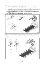
11
11
11
12
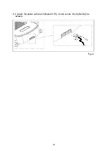
13
13
16
17
18
20
21
22
23
TABLE OF CONTENTS
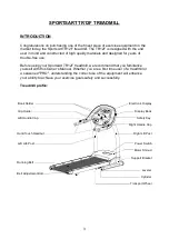
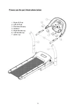
Introduction
1. Important Safety Instructions................................................................................
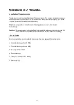
2. Assembling Your Treadmill....................................................................................
Installation Requirements.....................................................................................
List of Parts...........................................................................................................
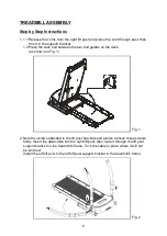
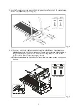
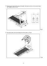
3. Treadmill Assembly...............................................................................................
Step by Step Instructions......................................................................................
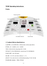
5. TR12F Operating Instructions.....................................................................................
Display...................................................................................................................
Feedback Window Specifications..........................................................................
Basic Information...................................................................................................
Safety Key Operation.............................................................................................
How to Operate TR12F Treadmill..........................................................................
6. Guideline For Exercise.........................................................................................
7. Adjust The Running Belt.......................................................................................
8. Belt Adjustment Procedure...................................................................................
9. Folding And Unfolding The Treadmill..................................................................
10. Floor Level Adjustment.......................................................................................
11. Main Fuse Failure...............................................................................................
12. Wiring Schematic...............................................................................................


