background image

2010.12

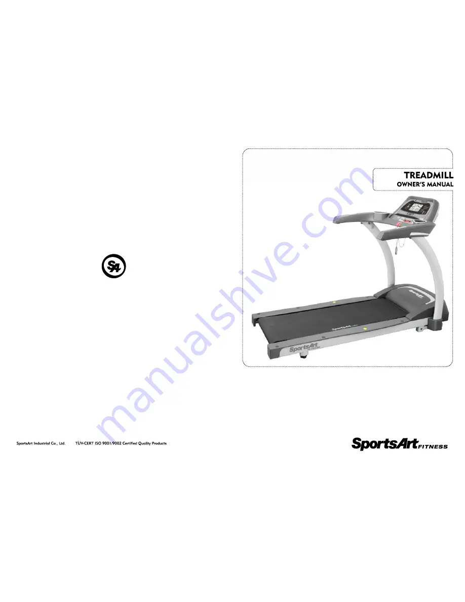
T613

Summary of Contents for T613

Page 1: ...2010 12 T613 ...

Page 2: ...lation STEP 2 Display Installation STEP 3 Moving the Treadmill STEP 4 Leveling the Unit STEP 5 Treadmill Walk Belt Tracking STEP 6 Treadmill Walk Belt Tightness Adjustment STEP 7 Power Cord Installation SCREEN DISPLAYS AND RANGE SPECIFICATIONS SAFETY FEATURES KEY FUNCTIONS 4 5 OPERATION AT START UP 5 1 QUICK START Mode 5 2 START Mode 5 3 OPERATION DURING EXERCISE 5 4 COOL DOWN 5 5 PROGRAM Function...

Page 3: ...E 8 1 TREADMILL LUBRICATION KIT 8 2 THE LUBRICATION PROMPT 8 3 CLEARING THE SERVICE NEEDED MESSAGE 8 4 MANUAL LUBRICATION PROCEDURE 8 5 MAINTENANCE SCHEDULE 8 6 MAINTENANCE TASK LIST TREADMILLS 8 7 MAINTENANCE ONE YEAR MAINTENANCE LOG 9 1 ERROR MESSAGES 9 2 OTHER MESSAGES CHAPTER 8 MAINTENANCE CHAPTER 9 WIRING SCHEMATIC 39 39 39 40 40 44 44 45 46 48 49 49 50 ...

Page 4: ......

Page 5: ......

Page 6: ......

Page 7: ......

Page 8: ...ge to the product Please save these instructions for future reference Make sure that product users abide by instructions in this manual This manual uses the following conventions for identifying special information Indicates additional information Indicates information to which you should pay special attention Indicates information to prevent harming the user or damaging the product Note Important...

Page 9: ......

Page 10: ...15 Programs Feedback Display Type LCD Heart Rate Control Yes Maximum User Weight 400 lbs 180 kgs Dimensions 1965mm x 970mmx 1345mm 78 X 38 X 53 TRACK RANDOM HILL INTV BRUCE GERKIN GLUTE Custom HR HRC 65 HRC 80 INCLINE DISTANCE TIME METS SPEED PACE CALORIES CAL HR HEART RATE WT LOSS 65 CARDIO 80 7 2 2 SPECIFICATIONS ...

Page 11: ......

Page 12: ......

Page 13: ...nic components make sure the power switch is off and the product is disconnected from the power outlet Be aware that some electronic components retain an electric charge for a few seconds after power supply is disconnected Be cautious during the installation and assembly of this equipment Think about the installation site and product location Set up the equipment on a solid level surface Provide e...

Page 14: ......

Page 15: ......

Page 16: ......

Page 17: ......

Page 18: ......

Page 19: ......

Page 20: ......

Page 21: ......

Page 22: ......

Page 23: ......

Page 24: ......

Page 25: ......

Page 26: ......

Page 27: ......

Page 28: ...otate in the center of the deck with equal spacing on both sides If the walk belt tends to one side turn the rear roller screw on that side clockwise no more than 1 4 turn This extends that side of the rear roller toward the back pushing the walk belt toward the other side ...

Page 29: ......

Page 30: ......

Page 31: ......

Page 32: ......

Page 33: ...0 1 MPH 0 1KPH To rapidly decrease the speed setting hold the speed key down speed values change rapidly The speed display shows actual speed 2 When this key is pressed during a workout the speed screen is displayed After three seconds the original display setting is resumed 3 INCLINE key makes the incline operate up 1 Each time this key is pressed the incline operates upward 0 5 Hold this key to ...

Page 34: ...to continue to see the present row of feedback Press this key again to see the other row of feedback Press this key again to scan alternating between rows of feedback 9 QUICK START key allows you to exercising without first inputting user information 10 START key allows you to exercise after inputting user information 11 Quick keys allow immediate selection of five incline and five speed settings ...

Page 35: ... the weight setting b Press the ENTER key to confirm your choice and proceed to the workout program setting mode 2 Workout Program Setting 1 Press the PROGRAM SCROLL key to select a workout program 2 Press the ENTER key to confirm your choice and proceed to set the workout goal 3 Note In BRUCE GERKIN and GLUTE workout programs the workout goal automatically is time The time goal depends on the wor...

Page 36: ...t change but continues to accumulate When a workout goal time or distance is obtained ACCU accumulated data appears After the accumulated workout data appears COOL which begins the following process speed decreases to below 2 5 MPH 4 KPH incline declines to 0 workout time shows 2 00 time counts down to 0 00 then the walk belt stops rotating and the start up banner screen appears on the display 1 T...

Page 37: ...m heart rate as calculated by 220 AGE 0 8 for 15 seconds 6 GERKIN This workout program is the GERKIN physical fitness test During this test speed and incline are controlled automatically by the treadmill these settings cannot be overridden by the user and other workouts cannot be activated When this 13 minute test is ompleted a score appears on the display The longer the user can exercise the high...

Page 38: ... Maximum speed can be changed during a workout by pressing SPEED keys or by pressing quick start speed keys The illustration screen will show and the previous maximum speed setting After adjusting the maximum speed setting press the ENTER key to confirm your choice c You can press incline up and down keys to directly control incline settings during heart rate control workouts 3 After a workout beg...

Page 39: ......

Page 40: ...n For best results install the product in a location free from interfering items 4 Place fitness products apart by at least100 cm to avoid having the heart rate value from an exerciser on one product appear on another product 5 Heart rate values are for comparison only Do not use them for medical treatment or other purposes It is easy to use the contact heart rate mechanism Simply put both hands o...

Page 41: ...est In cold dry areas static electricity can interfere with unit operation In such environments touching metal may cause static electrical shocks Suggestions Before touching metal touch a material with electrically isolative properties for instance plastic or foam to avoid shocks from static electricity Because heart rate contact plates are made of metal to avoid static shock first touch foam grip...

Page 42: ......

Page 43: ......

Page 44: ......

Page 45: ......

Page 46: ......

Page 47: ...ON appears Press the STOP key to complete the lubrication procedure The treadmill will recalculate the total distance and operate normally A When the SERVICE NEEDED APPLY LUBE message appears simultaneously press and hold INCLINE INCLINE 0 for two seconds The motor will operate at a low speed allowing lubricant to spread evenly on the walk belt The display will show the following message PLEASE PR...

Page 48: ......

Page 49: ... walk belt as necessary 1 Inspect the walk deck for wear The surface of the deck should be smooth without cracks or grooves Wipe the deck clean If necessary flip the deck to wear the other side or replace the deck as needed 2 Inspect the rotation of rollers on walk belt guides They should spin freely 3 Inspect the front roller for normal rotation It should spin freely without excessive noise Clean...

Page 50: ...d Do NOT use cleaners with alcohol ammonia or other damaging chemicals The use of such chemicals can damage the product and void the warranty Never spray or pour any liquid directly onto the product Doing so can damage electronic components and void the warranty This product has moving parts that can be hazardous Exercise caution when maintaining operating or moving this product ...

Page 51: ......

Page 52: ... Power switch is OFF E4 2 Power supply voltage is too low Action needed Please wait for power supply recovery and restart the unit E4 3 Power supply voltage is too high Action needed Please wait for power supply recovery and restart the unit E8_1 Communication abnormality at start up E8_2 Communication abnormality during operation FOR ACCURATE HR HOLD SENSORS FIRMLY WHILE WALKING This message emph...

Page 53: ......

Page 54: ...E 8 1 TREADMILL LUBRICATION KIT 8 2 THE LUBRICATION PROMPT 8 3 CLEARING THE SERVICE NEEDED MESSAGE 8 4 MANUAL LUBRICATION PROCEDURE 8 5 MAINTENANCE SCHEDULE 8 6 MAINTENANCE TASK LIST TREADMILLS 8 7 MAINTENANCE ONE YEAR MAINTENANCE LOG 9 1 ERROR MESSAGES 9 2 OTHER MESSAGES CHAPTER 8 MAINTENANCE CHAPTER 9 WIRING SCHEMATIC 39 39 39 40 40 44 44 45 46 48 49 49 50 ...

Page 55: ... walk belt as necessary 1 Inspect the walk deck for wear The surface of the deck should be smooth without cracks or grooves Wipe the deck clean If necessary flip the deck to wear the other side or replace the deck as needed 2 Inspect the rotation of rollers on walk belt guides They should spin freely 3 Inspect the front roller for normal rotation It should spin freely without excessive noise Clean...

Reviews: