background image

Installation of the Vacuum Pump Interface on the 

SRI 8610C GC 


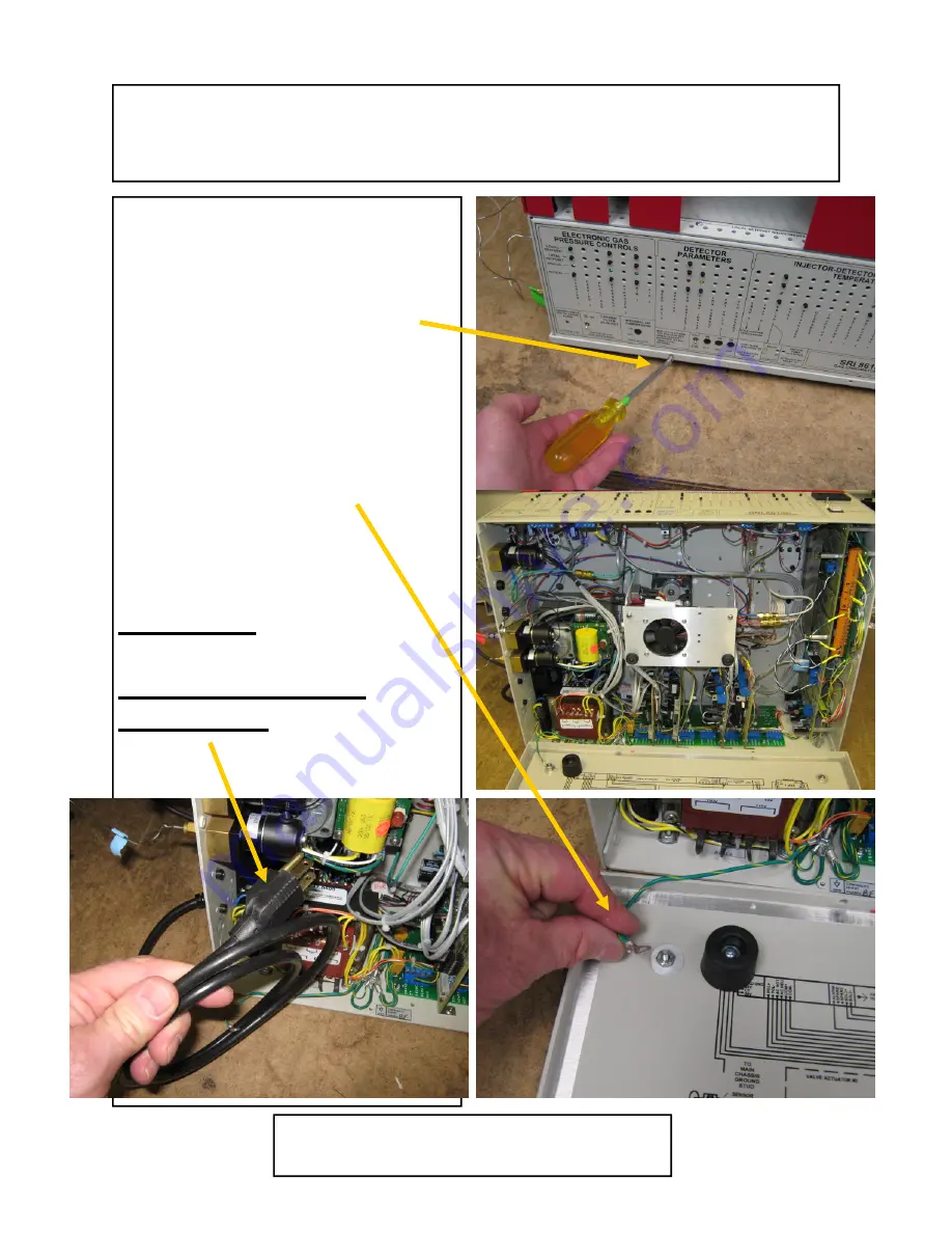
Remove the six Phillips head 
screws holding the bottom of the 
GC. 
 
Tilt the GC on its back and remove 
the bottom cover.   Disconnect the 
ground wire so the bottom cover 
can be moved out of the way. 


Important: 
 
Disconnect the AC 
power cord 

December 2009 

Page 1 

SRI Tech Support 310-214-5092  

www.srigc.com 

Summary of Contents for 8610C GC

Page 1: ...hillips head screws holding the bottom of the GC Tilt the GC on its back and remove the bottom cover Disconnect the ground wire so the bottom cover can be moved out of the way Important Disconnect the AC power cord December 2009 Page 1 SRI Tech Support 310 214 5092 www srigc com ...

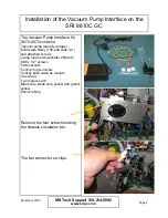
Page 2: ...nd attached screws 2 amp fuse and fuseholder 250volts 4 6 x 1 2 screws 5 6 locknuts 5 crimp ring terminals 3 sticky back cable tie mounts 3 tie wraps Two meters each Black wire white wire yellow and green yellow Shrink tubing Remove the four screws holding the chassis circulation fan The fan connector un clips December 2009 Page 2 SRI Tech Support 310 214 5092 www srigc com ...

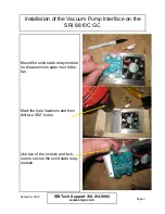
Page 3: ...ount the solid state relay module on the aluminum plate next to the fan Mark the hole locations and then drill two 5 32 holes Use two of the screws and lock nuts to secure the solid state relay module December 2009 Page 3 SRI Tech Support 310 214 5092 www srigc com ...

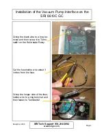
Page 4: ...a ring ter minal and then screw it to Termi nal 1 on the Solid state Relay Cut the fuseholder wire about 3 inches from the fuse Crimp the longer side of the fuse holder wire to a ring terminal and then fasten to Terminal 2 December 2009 Page 4 SRI Tech Support 310 214 5092 www srigc com ...

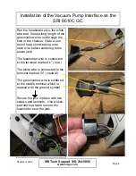
Page 5: ...4 Snap the plastic cover over the solid state relay module Replace the aluminum plate letting the four wires dangle for the time being Use a hammer and screwdriver to remove the knock out plate for the power jack located on the rear of the GC s right side Use a file to smooth the edges of the hole so the jack slides in easily December 2009 Page 5 SRI Tech Support 310 214 5092 www srigc com ...

Page 6: ...before soldering to the power jack The fuseholder wire is connected to the terminal marked L line The white wire is connected to the terminal marked N neutral The green yellow wire is soldered to the middle terminal which is marked with the ground symbol Secure the jack in place with two screws and locknuts Use a stick pad and tiewrap to secure the fuseholder near the jack December 2009 Page 6 SRI...

Page 7: ...ellow wire from the solid state relay to the A D board terminal labeled D The A D board has eight digital outputs A H The yellow wire can be con nected to any of the digital outputs if desired but we normally use D unless it is already occupied with some other function Route the wires neatly through the GC Often there will already be a wire bundle and clamp through which you can run the wires Dece...

Page 8: ...r jack black from soild state relay to the third and fourth terminals from the left on the display board There will already be a white and black wire inserted into these terminals On the model 310C GC connect to the two rightmost terminals in stead December 2009 Page 8 SRI Tech Support 310 214 5092 www srigc com ...

Page 9: ...ace Then test the actual vacuum pump by turn ing Relay D if that s the one you assigned on and off us ing the View Relay Window screen in PeakSimple A simple schematic of the vacuum pump interface wiring is shown below December 2009 Page 9 SRI Tech Support 310 214 5092 www srigc com SSR White wire black wire fuse yellow wire Green yellow wires A D board Power jack AC line Chassis ground stud ...

Reviews: