Summary of Contents for Korando 2012
Page 1: ......
Page 2: ......
Page 3: ......
Page 4: ......
Page 5: ......
Page 6: ......
Page 7: ......
Page 8: ......
Page 9: ......
Page 10: ......
Page 11: ......
Page 12: ......
Page 13: ......
Page 14: ......
Page 15: ......
Page 16: ......
Page 17: ......
Page 18: ......
Page 19: ......
Page 20: ......
Page 21: ......
Page 22: ......
Page 23: ......
Page 24: ......
Page 25: ......
Page 26: ......
Page 27: ......
Page 28: ......
Page 29: ......
Page 30: ......
Page 31: ......
Page 32: ......
Page 33: ......
Page 34: ......
Page 35: ......
Page 36: ......
Page 37: ......
Page 38: ......
Page 39: ......
Page 40: ......
Page 41: ......
Page 42: ......
Page 43: ......
Page 44: ......
Page 45: ......
Page 46: ......
Page 47: ......
Page 48: ......
Page 49: ......
Page 50: ......
Page 51: ......
Page 52: ......
Page 53: ......
Page 54: ......
Page 55: ......
Page 56: ......
Page 57: ......
Page 58: ......
Page 59: ......
Page 60: ......
Page 61: ......
Page 62: ......
Page 63: ......
Page 64: ......
Page 65: ......
Page 66: ......
Page 67: ......
Page 68: ......
Page 69: ......
Page 70: ......
Page 71: ......
Page 72: ......
Page 73: ......
Page 74: ......
Page 75: ......
Page 76: ......
Page 77: ......
Page 78: ......
Page 79: ......
Page 80: ......
Page 81: ......
Page 82: ......
Page 83: ......
Page 84: ......
Page 85: ......
Page 86: ......
Page 87: ......
Page 88: ......
Page 89: ......
Page 90: ......
Page 91: ......
Page 92: ......
Page 93: ......
Page 94: ......
Page 95: ......
Page 96: ...MODIFIED ITEMS 1 EXTERIOR 2 INTERIOR 3 CHASSIS 2 4 6 ...
Page 103: ......
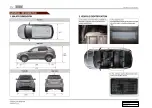
Page 104: ...01 3 0000 00 1 LAYOUT Right side view Left side view Rear view Front view ...
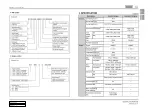
Page 114: ...01 13 0000 00 4 CODING AND SETUP 1 Engine Variant Coding ...
Page 131: ......
Page 136: ...02 7 0000 00 ...
Page 137: ...02 8 ...
Page 138: ...02 9 0000 00 ...
Page 139: ...02 10 ...
Page 154: ...02 25 0000 00 Timing gear cover case TGCC TGCC Oil seal Screw plug ...
Page 169: ...03 12 4 Fuel System Check Procedure ...
Page 184: ...03 27 0000 00 3 Input Output devices ...
Page 186: ...03 29 0000 00 4 Flow Diagram of Fuel Supply System ...
Page 187: ...03 30 5 Circuit Diagram ...
Page 193: ...04 8 3 INPUT OUTPUT OF INTAKE SYSTEM ...
Page 194: ...04 9 0000 00 4 OPERATING PROCESS Work Flow ...
Page 197: ...04 12 5 CIRCUIT DIAGRAM ...
Page 198: ...05 3 0000 00 1 TROUBLESHOOTING 1 Work Flow ...
Page 201: ...05 6 3 OPERATING PROCESS 1 Exhaust Gas Flow 2 Input Output Devices ...
Page 209: ...06 10 Defects caused by reasons other than that of the turbocharger 4 ...
Page 211: ...06 12 2 Work Flow for Troubleshooting ...
Page 212: ...06 13 0000 00 ...
Page 213: ...06 14 ...
Page 214: ...06 15 0000 00 ...
Page 215: ...06 16 ...
Page 219: ...06 20 3 INPUT OUTPUT DEVICES ...
Page 226: ...07 7 0000 00 1 Operation Flow 2 OPERATING PROCESS ...
Page 235: ...08 10 3 System Layout ...
Page 236: ...08 11 0000 00 ...
Page 240: ...09 6 3 Checking Battery ...
Page 246: ...09 12 2 CHARGING OPERATION 1 With Smart Key System ...
Page 247: ...09 13 0000 00 2 Without SMART Key System ...
Page 248: ...09 14 3 CIRCUIT DIAGRAM ...
Page 252: ...10 6 2 SYSTEM OPERATION 1 Input Output Diagram of Glow Plug Control Unit 2 System Diagram ...
Page 253: ......
Page 254: ...10 8 3 Circuit Diagram ...
Page 255: ...10 9 1413 00 ...
Page 260: ...10 14 When there is no engine cranking signal after turning the ignition key ON ...
Page 265: ...11 7 1461 00 2 With SMART key system ...
Page 266: ...11 8 3 Without SMART key system ...
Page 267: ......
Page 268: ...11 10 2 Circuit Diagram 1 With SMART key system ...
Page 269: ...11 11 1461 00 ...
Page 270: ...11 12 2 Without SMART key system ...
Page 271: ...11 13 1461 00 ...
Page 286: ...13 6 2 OPERATING PROCESS 1 Schematic Diagram ...
Page 298: ...14 13 1114 00 6 OPERATING TEMPERATURE ...
Page 299: ...14 14 7 ELECTRIC CIRCUIT DIAGRAM ...
Page 304: ...15 6 2 SYSTEM OPERATION 1 Input Output of ECU 1 ECU Block diagram ...
Page 318: ...15 20 b Input Output for variable swirl valve ...
Page 323: ...15 25 0000 00 c Input Output of E EGR system ...
Page 327: ...15 29 0000 00 c Input Output for E VGT system ...
Page 330: ...15 32 c Input Output for oxygen sensor ...
Page 333: ...15 35 0000 00 c Input Output for cooling fan and A C compressor ...
Page 343: ...15 45 0000 00 c Input Output for CDPF control ...
Page 348: ...15 50 3 Input Output for CAN communication ...
Page 391: ...04 9 1740 01 4 INPUT OUTPUT DEVICES ...
Page 392: ...04 10 5 CIRCUIT DIAGRAM ...
Page 397: ......
Page 400: ...03 10 3 SCHEMATIC DIAGRAM OF FUEL FLOWS ...
Page 402: ...05 3 1745 01 1 TROUBLESHOOTING ...
Page 407: ...05 8 PCV valve 2 COMPONENTS Engine ECU WCC Engine CHECK lamp Blow by hose Exhaust manifold ...
Page 409: ...05 10 3 WORK FLOW IN EXHAUST SYSTEM ...
Page 410: ...05 11 1745 01 4 INPUT OUTPUT DEVICES ...
Page 412: ...06 4 2 LAYOUT Ignition Coil Bolt Spark Plug 1 2 3 ...
Page 414: ...06 6 2 COMPONENTS Ignition coil Camshaft position sensor Knock sensor Injector Spark plug ...
Page 416: ...06 8 3 INPUT OUTPUT DEVICES ...
Page 417: ......
Page 418: ...06 10 4 CIRCUIT DIAGRAM ...
Page 419: ...06 11 1443 01 ...
Page 427: ...09 4 2 LAYOUT 1 Alternator Alternator assembly Bolt 1 2 ...
Page 431: ...09 8 2 Battery Inspection ...
Page 436: ...09 13 1452 01 2 CHARGING OPERATION 1 Vehicle without Smart key system ...
Page 437: ...09 14 2 Circuit Diagram ...
Page 439: ...11 4 2 LAYOUT Starter Bolt 1 2 ...
Page 442: ...11 7 1462 01 2 OPERATING PROCESS ...
Page 443: ...11 8 3 CIRCUIT DIAGRAM ...
Page 447: ...15 6 2 SYSTEM OPERATION 1 Input Output of ECU ...
Page 452: ...15 11 0000 00 3 Input Output for Injection Volume Control ...
Page 453: ...15 12 4 Basic Injection Volume Map ...
Page 455: ...15 14 3 Input Output for Ignition System ...
Page 460: ...15 19 0000 00 3 Input Output for Cooling Fan and A C Compressor ...
Page 466: ...15 25 0000 00 3 Input Output for CAN communication ...
Page 468: ......
Page 471: ...01 5 0000 00 VIN NO Engine NO ...
Page 475: ...01 9 0000 00 4 SCHEDULED MAINTENANCE SERVICES ...
Page 476: ...01 10 ...
Page 477: ...01 11 0000 00 ...
Page 478: ......
Page 480: ......
Page 490: ......
Page 492: ......
Page 494: ...02 6 2 COOLANT FLOWS IN COOLING SYSTEM ...
Page 495: ...02 7 0000 00 ...
Page 515: ...14 20 4 CIRCUIT DIAGRAM ...
Page 517: ......
Page 521: ...01 6 Sun visor lamp Glove box lamp Front room lamp 2 INTERIOR LAMP SYSTEM LAYOUT ...
Page 522: ...01 7 0000 00 Center room lamp Luggage lamp Door courtesy lamp ...
Page 525: ...01 10 4 SCHEMATIC DIAGRAM FOR WIRING AND ELECTRICAL DEVICES 1 Wiring Harness Arrangement ...
Page 526: ...01 11 0000 00 2 Electrical Devices Mounting Locations ...
Page 527: ...01 12 3 Connector Ground And Splice Pack Connector ...
Page 528: ...01 13 0000 00 Ground Splice pack ...
Page 531: ......
Page 537: ...02 8 Engine compartment fuse and relay box I ...
Page 538: ...02 9 8410 00 ...
Page 539: ...02 10 Engine compartment fuse and relay box II ...
Page 540: ...02 11 8410 00 ...
Page 541: ...02 12 Engine compartment fuse and relay box IV ...
Page 542: ...02 13 8410 00 ...
Page 543: ...02 14 Engine compartment fuse and relay box V ...
Page 544: ...02 15 8410 00 ...
Page 546: ......
Page 547: ...02 18 Interior fuse and relay box I ...
Page 548: ...02 19 8410 00 ...
Page 549: ...02 20 Interior fuse and relay box II ...
Page 550: ...02 21 8410 00 ...
Page 551: ...02 22 Interior fuse and relay box III ...
Page 552: ...02 23 8410 00 ...
Page 553: ...02 24 Interior fuse and relay box IV ...
Page 554: ...02 25 8410 00 ...
Page 570: ...03 13 8710 01 ...
Page 586: ...03 29 8710 01 ...
Page 638: ...03 96 Select EMS registration menu and enter the password default value 0000 Press Next 3 ...
Page 640: ...03 98 Once the EMS registration is completed press OK to exit the program 6 ...
Page 643: ...03 101 0000 00 Turn the ignition on and press OK button 6 Wait for 15 seconds 5 ...
Page 644: ......
Page 647: ...04 5 8712 03 Slot Rear bumper antenna Front interior antenna Rear interior antenna Smart key ...
Page 652: ...04 10 Passive start operation range Passive START actuation area Vehicle interior ...
Page 666: ...04 24 6 Power Relay Control integrated with ICM 1 OFF to engine starting 2 ACC to IGN ...
Page 667: ...04 25 8712 03 3 IGN to starting 4 IGN engine ON to ACC 5 IGN engine ON to OFF ...
Page 681: ...04 75 8712 03 When the registration is completed click OK button 6 ...
Page 684: ......
Page 690: ...05 8 Engine RPM gauge Speedometer STD LCD ...
Page 691: ...05 9 8010 01 1 SVC 3 Description of Warning Lamps Indicators ...
Page 692: ...05 10 2 STD ...
Page 700: ...05 18 1 SVC 4 OPERATING PROCESS 2 STD ...
Page 701: ......
Page 702: ...05 20 SVC 3 Block Diagram ...
Page 703: ...05 21 8010 01 ...
Page 704: ...05 22 STD ...
Page 705: ...05 23 8010 01 ...
Page 711: ...05 29 8010 01 1 SVC Symbols in SVC 6 System Analysis ...
Page 712: ...05 30 Symbols in SVC via CAN ...
Page 714: ...05 32 2 STD Symbols in STD ...
Page 716: ...05 34 Symbols in STD via CAN ...
Page 717: ...05 35 8010 01 ...
Page 772: ...06 42 Tailgate open switch 7 TAILGATE SWITCH Tailgate open switch ...
Page 784: ...07 12 Sun visor lamp Glove box lamp Front room lamp 1 Layout 2 INTERIOR LAMPS ...
Page 785: ...07 13 8310 00 Center room lamp Luggage lamp Door courtesy lamp ...
Page 794: ......
Page 806: ...08 21 7810 00 System layout 1 Rain sensor coupled wiper operation LIN ...
Page 813: ...08 28 Speed sensitive intermittent wiper interval ...
Page 816: ......
Page 818: ...09 7 8790 00 2 CONFIGURATION Installation of PAS sensor Parking aid unit PAS sensor ...
Page 821: ...09 10 Circuit diagram of ECU Internal circuit diagram of sensors ...
Page 833: ......
Page 838: ......
Page 884: ......
Page 885: ...02 22 3 Hydraulic Circuit Diagram ...
Page 886: ...02 23 3680 01 ...
Page 888: ...02 25 3680 01 3 Drive 2nd 2nd Auto 2 375 1 Power flow 4 Drive 3rd 3rd Auto 1 522 1 Power flow ...
Page 889: ...02 26 5 Drive 4th 4th Auto 1 144 1 Power flow 6 Drive 5th 5th Auto 0 859 1 Power flow ...
Page 890: ...02 27 3680 01 7 Drive 6th 6th Auto 0 676 1 Power flow 8 Reverse 3 178 1 Power flow ...
Page 891: ...02 28 9 Neutral Park Power flow ...
Page 898: ...03 9 3190 01 2 Internal Configuration ...
Page 901: ...03 12 Reverse gear 4th speed gear 5th speed gear 6th speed gear ...
Page 927: ...07 13 3280 17 2 Circuit Diagram ...
Page 928: ...07 14 3 Block Diagram of Input Output ...
Page 932: ...08 5 0000 00 2 TIGHTENING TORQUE Front suspension assembly ...
Page 933: ...08 6 Rear suspension assembly ...
Page 952: ...09 12 4 CIRCUIT DIAGRAM OF STOP LAMP ...
Page 953: ...09 13 4850 00 ...
Page 955: ...10 4 ABS ESP CBS Circuit diagram of wheel speed sensor ...
Page 963: ...10 12 5 SYSTEM OPERATION 1 Block Diagram of ABS HECU ...
Page 974: ...10 23 4890 00 7 CIRCUIT DIAGRAM ...
Page 983: ...11 11 0000 00 5 SYSTEM DESCRIPTION 1 Block Diagram of ESP HECU ...
Page 1007: ...13 4 2 TIGHTENING TORQUE ...
Page 1035: ...01 14 4 A C COOLING CIRCUIT ...
Page 1036: ......
Page 1037: ...01 16 5 CIRCUIT DIAGRAM ...
Page 1038: ...01 17 6810 00 ...
Page 1045: ......
Page 1055: ...02 19 8810 00 5 CIRCUIT DIAGRAM 8810 01 Air bag Curtain air bag Side air bag ...
Page 1061: ...04 4 Sunroof switch 1 SYSTEM LAYOUT Sunroof assembly TILT OPEN Sunroof motor control unit ...
Page 1068: ...04 11 7340 00 5 CIRCUIT DIAGRAM ...
Page 1072: ......
Page 1073: ...07 3 5110 01 Top view Side view Front side Rear view 1 MAJOR DIMENSION ...
Page 1074: ...07 4 2 JACK POINTS 1 2WD ...
Page 1075: ...07 5 5110 01 2 4WD ...
Page 1076: ...07 6 3 SEALING APPLICATION POINTS 1 Dash Panel Engine Tunnel Floor Etc ...
Page 1077: ...07 7 5110 01 2 White Body ...
Page 1078: ...07 8 ...
Page 1079: ...07 9 5110 01 3 Front Rear Door Panel ...
Page 1080: ...07 10 4 Engine Hood Panel ...
Page 1081: ...07 11 5110 01 4 DEADENER APPLICATION POINTS ...
Page 1082: ...07 12 5 UNDER COATING ...
Page 1083: ...07 13 5110 01 6 MAJOR WELDING POINTS 1 Cross Sectional View of Major Panels ...
Page 1084: ...07 14 2 Side Panel ...
Page 1085: ...07 15 5110 01 3 Front Panel ...
Page 1086: ...07 16 4 Apron Panel ...
Page 1087: ...07 17 5110 01 5 Dash Cowl Panels ...
Page 1088: ...07 18 6 Front H Frame Panel ...
Page 1089: ...07 19 5110 01 7 Front Floor Panel ...
Page 1090: ...07 20 8 Rear Floor Panel ...
Page 1091: ...07 21 5110 01 9 Rear End Panel ...
Page 1092: ...07 22 10 Roof Panel ...
Page 1093: ...07 23 5110 01 7 MAJOR BODY DIMENSIONS 1 Under Body Unit mm ...
Page 1094: ...07 24 2 Vehicle Structure Unit mm ...
Page 1095: ...07 25 5110 01 3 Side Structure Unit mm ...
Page 1096: ...07 26 4 Windshield Glass Area Unit mm ...
Page 1097: ...07 27 5110 01 5 Tail Gate Area Unit mm ...
Page 1098: ...07 28 6 Front End Unit mm ...
Page 1099: ...07 29 5110 01 7 Engine Compartment Unit mm ...
Page 1100: ...07 30 8 Back Panel Unit mm ...
Page 1101: ...07 31 5110 01 8 GAP CHART 1 Side Body Unit mm ...
Page 1102: ...07 32 2 Front Unit mm ...
Page 1103: ...07 33 5110 01 3 Rear Unit mm ...
Page 1104: ......


