background image

CP155C / CP175C / CP1000C

GPS Chartplotter

Owner's Manual

Summary of Contents for CP1000C

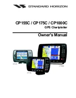
Page 1: ...CP155C CP175C CP1000C GPS Chartplotter Owner s Manual ...

Page 2: ...causeharmfulinterference with radio communications There is no guarantee that interference will not occur in a particular instance If this equipment does cause harmful interference to other equipment try to correct the problem by relocating the equipment Consult an authorized STANDARD HORIZION dealer or other qualified service technician if the problem cannot be corrected Operation is subject to t...

Page 3: ...s a very important operation and must be done carefully Since the surface is covered by a antireflective coating the procedure for cleaning all the surfaces can be performed using the following procedure You need a tissue or lens tissue and a cleaning spray containing Isopropanol a normal spray cleaner sold for the PC screen for example PolaClear by Polaroid Fold the tissue or lens tissue into a t...

Page 4: ...artridge holder Extensive exposure to heat may result in damage to the chartplotter The chartplotter contains dangerous high voltage circuits which only experienced technicians can handle STANDARD HORIZON will not be liable for errors contained herein or for incidental or consequential damages in connection with the performance or use of this material ...

Page 5: ...ITION ON A VHF RADIO 20 2 8 OPTIONAL BLACK BOX FISH FINDER 21 2 9 CONNECTING DIGITAL INSTRUMENTS AUTOPILOT RADAR 21 2 10 OUTPUTTING NMEA TO A PERSONAL COMPUTER 21 2 11 NMEA DATA PAGE 22 2 12 VIDEO INPUT for CP1000C only 22 2 12 0 Video Camera Input 22 2 12 1 VCR or DVD Input 22 2 13 OPTIONAL C MAP NT CARTOGRAPHY 24 2 14 INSERTING THE C CARD 24 3 CONTROLS AND INDICATORS 25 3 0 CONTROLS AND CONNECTI...

Page 6: ... OTHER SETTINGS IN ROUTE MENU 47 8 TRACKS 49 8 0 TRACKING 49 8 0 0 Saving and starting a new Track 50 8 0 1 Other Settings in Track Menu 50 8 1 USING THE TRIP LOG 50 8 1 0 Resetting the Trip Log 51 9 USER C CARD 53 9 0 USER C CARD MENU 53 9 0 0 Formatting the User C CARD 53 9 0 1 Transferring files to the optional User C CARD 54 9 0 2 Loading a file 54 9 0 3 Deleting a file from the User C CARD 54...

Page 7: ...GATE 67 11 2 COMPASS 68 11 3 ALARMS 69 12 TROUBLE SHOOTING 71 13 TECHNICAL TESTS 73 13 0 SYSTEM TEST 73 13 0 0 RAM Menu reset 73 13 0 1 DIM Menu 73 13 0 2 Cartridges 74 13 0 3 Serial Ports 74 13 0 4 Modem test 74 14 SPECIFICATIONS 75 14 0a CP155C SPECIFICATIONS 75 14 0b CP175C SPECIFICATIONS 76 14 0c CP1000C SPECIFICATIONS 77 14 1 Smart WAAS Receiver Specifications 78 15 APPENDIX TERMS 79 INDEX 81...

Page 8: ...Page 10 GPS chartplotters ...

Page 9: ... for CP155C 600 Waypoints Marks 20 Routes storage for CP175C 1000 Waypoints Marks 20 Routes storage for CP1000 3000 Waypoints Marks 50 Routes storage User selectable data fields NMEA Data pages 3 NMEA Output and 3 Inputs Connections to and from STANDARD HORIZON DSC VHF s for Distress and Position Request calls 3 year limited warranty lifetime flat rate 1 1 PACKING LIST When the package containing ...

Page 10: ...CEMENT PART ITEM XUS0003907 Bracket XUS0003908 Protective Cover XUS0003909 Flush mounting screws XUS0003910 Flush mount template XUS0003913 2 amp fuse and holder XUS0003911 Smart DGPS WAAS Antenna XUCMP0066 Owner s Manual XUCMP0067 Quick Reference Guide 1 2 OPTIONAL ACCESSORIES 1 2 0a CP155C Optional Accessories PART NUMBER ITEM RR150003CP Overhead mounting bracket Figure 1 2 0a CP155C Bracket 1 2...

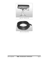
Page 11: ...GPS chartplotters Page 13 Figure 1 2 0b Color Video Camera Figure 1 2 0ba Extension Cable ...

Page 12: ...Page 14 GPS chartplotters ...

Page 13: ...e chartplotter especially while under way After the location is found attach the mounting base to the area using the supplied hardware Figure 2 1 Installing removing chartplotter Bracket 2 2 FLUSH MOUNTING The GPS chartplotter is supplied with a flush mount template for the cutout hole and screw holes required to install the chartplotter NOTE Before drilling holes ensure there are no obstructions ...

Page 14: ... is not located within 3 FT of RADAR or other transmitting antenna Ensure there are no major obstructions or fixtures in the immediate proximity to the antenna The antenna relies on direct line of sight satellite reception If you are unsure of the chosen location temporarily mount the antenna in the desired location to verify correct operation If mounted close to RADAR and after the GPS chartplott...

Page 15: ...r RTV to the under side of the antenna 7 Place the antenna and then screw it into place using the screws In some cases the screw may not be long enough if this happens simply apply more RTV to the underside of the antenna to glue it into place Figure 2 3 0 Installing the GPS Smart antenna Figure 2 3 0 Installing the GPS Smart antenna Flush 2 4 CONNECTIONS The GPS chartplotter has a cable or connec...

Page 16: ...und and Black wire of GPS Antenna NOTE The CP155C and CP1000C have connectors on the rear panel that allow the GPS Smart antenna to be directly connected Video Connector for CP1000C Pin Description Connection Example 1 Ground Connect to Video Signal Ground of DVD VCR Video Cameras 2 9 12 VDC Connect to Video Cameras Power Input 3 Video Signal Connect to Video Signal of DVD VCR Video Cameras 2 4 0b...

Page 17: ...GPS chartplotters Page 19 2 4 1a Connection for CP155C 2 4 1b Connection for CP175C 2 4 1c Connection for CP1000C ...

Page 18: ... a DSC Distress Call or even Poll the location of another vessel and show the position of that vessel on the display of STANDARD HORIZON VHFs STANDARDHORIZONhastakenthisfeatureonestepfurther iftheStandardHorizonGPS chartplotter is connected a STANDARD HORIZON DSC capable VHF the vessel in Distress or the polled position of the vessel is shown on the display of the GPS chartplotter making it easy t...

Page 19: ...veNMEA output Depth Sounder Speed Log with temperature Wind Speed and Direction Flux Gate Compass Auto Pilot and Radar Figure 2 9 Connecting Digital Instruments Autopilot Radar 2 10 OUTPUTTING NMEA TO A PERSONAL COMPUTER The GPS chartplotter can be connected to output Marks Routes and tracks to many PC programs available in the aftermarket To send or receive User points the PC Program must be able...

Page 20: ...A DISPLAY with the ShuttlePoint knob 2 Press ENTER or move the ShuttlePoint knob to the right and highlight DATA 3 Press ENTER or move the ShuttlePoint knob to show the NMEA DATA page 4 Connect the BLUE Wire on the GPS chartplotter to the junction of the Brown wire and the VHF wire The display should look similar to the picture below Figure 2 11 NMEA Data page 2 12 VIDEO INPUT for CP1000C ONLY 2 1...

Page 21: ...oring the factory defaults for the Input 1 and Input 2 picture adjustment The user can decide to reset the default for Input 1 or Input 2 individually or to restore the defaultsofthetwoVideoInputsimultaneously WhenRestoredefaultisexecuted the message OK is shown next to the selected menu item NOTE If the video signal is not present on the video connector the corresponding item in the menu will be ...

Page 22: ...ase the familiarity and usability of the much larger coverage database of NT NT is supplied by C MAP in four sizes Local Standard Wide and SuperWide For convenience the older NT and the NT are both compatible with all STANDARD HORIZON chartplotters Contact C MAP USA at 508 477 8010 or visit www c map com for further information on NT 2 14 INSERTING THE C CARD Hold the C CARD by the long inclined s...

Page 23: ...e ShuttlePoint knob The ShuttlePoint knob moves the cursor about on the display screen quickly and accurately It also scrolls the desired option in the menu page s It allows to exit from Home mode to Cursor mode When into menu pages moving it to right selects the desired option as ENTER moving it to the left exits from menu as CLEAR For a detailed explanation of Cursor VS home mode refer to sectio...

Page 24: ...tlePoint knob up down changes the value pressing the ShuttlePoint knob left right moves the cursor to the previous next location 3 0b The soft keys on CP175C CP1000C The 5 keys in the bottom part of the front panel hereinafter named soft keys have different functions associated depending on the software their labels are shown on the screen immediately above the keys the user can customize the func...

Page 25: ...t knob to the left and you will notice a cross hair appears this is called the cursor 5 When you move the ShuttlePoint knob you will notice DST and BRG values in the Data window change This shows the Distance and Bearing from the GPS Fix of your vessel to the position of the Cursor 6 If the cursor is moved to the edge of the screen the chartplotter will automatically pan in the desired direction 3...

Page 26: ... ShuttlePoint knob to the right 2 Move the ShuttlePoint knob to CURSOR SPEED and press ENTER or move the ShuttlePoint key to the right 3 Themenunowshowstwoselections CHARTandMENUwhichallowsthecursorspeed to be selected to High Medium or low on Chart page or within the menus 4 With CHART or MENU selected press ENTER or move the ShuttlePoint knob to the right Move the ShuttlePoint knob to the desire...

Page 27: ...cklightintensityorupordown to change the LCD contrast Press ENTER to set Figure 3 1 4 Backlight and Contrast adjustment 3 1 5 Selecting North Up or Course Up The default selection is NORTH UP however you may want the top of the Chart Page oriented so it will always show the area ahead of the direction your vessel is traveling which is called COURSE UP Figure 3 1 5 General Setup menu 1 Press MENU m...

Page 28: ... in Universal Time Coordinates UTC or Greenwich England Mean Time To change the chartplotter to read the correct time first youmustfigureouttheoffsetandifitisdaylightsavingstime ForexampleontheWestcoast of the United States or Pacific Standard Time the offset needed would be 08 00 or 07 00 fordaylightsavingstime EasternStandardTime 05 00or 04 00fordaylightsavingstime Figure 3 2 Adjusting Time NOTE...

Page 29: ...ange the hour 9 Repeat this method to change the minutes if necessary 10 Once you have the correct GPS time offset press ENTER to set 3 3 SELECTING LORAN TD OR OTHER COORDINATE SYSTEM The GPS Fix coordinates can be changed to show Latitude Longitude Loran TD s or UTM Below is the window that will appear when customizing the coordinate system Figure 3 3 Coordinate System Menu 1 Press MENU and move ...

Page 30: ...ShuttlePoint knob to the right 3 Move the ShuttlePoint knob to select DISPLAY COLOR and press ENTER or move the ShuttlePoint knob to the right 4 A popup window will be shown with Normal Classic Night and Sunlight move the ShuttlePoint knob to the desired selection and press ENTER or move the ShuttlePoint knob to the right 5 Press CLEAR or move the ShuttlePoint knob to the left to exit the menu and...

Page 31: ...onnected the any of the key can be customized to show 50 or 200kHz full page 50 or 200kHz Chart Fish split screen and zoom screens Figure 3 6 Window options of the selected Soft Key 1 To change momentarily press any of the Soft Keys then press and hold the key you want to customize 2 A popup window will be shown with the above settings 3 Move the ShuttlePoint knob up or down to select the desired ...

Page 32: ...Distance and bearing from the vessels location to the cursor This selection allows the window to be turned off ZOOM TYPE The default setting changes scales in or out with each press of the ZOOM IN or ZOOM OUT key When ZOOM BY SCALE is selected and either the ZOOM IN or OUT key is pressed a popup window is shown allowing you to choose the scale to zoom to using the ShuttlePoint knob MAP ORIENTATION...

Page 33: ...indowwillshowthename distanceandpositionoftheServicesclosest to your location 6 UsingtheShuttlePointknob highlightthedesiredServiceandpress ENTER whichwill show the name and phone number of the Service 7 Press CLEAR which will show the available Services at the location 8 Press CLEAR to show the actual position of the Services Figure 4 0 Port Services 4 1 OTHER AVAILABLE SEARCHES PORT Search and s...

Page 34: ...Page 36 GPS chartplotters ...

Page 35: ...ain 5 0 CREATING A NEW MARK USING THE CHART PAGE 1 Move the ShuttlePoint knob to the desired or approx Lat Lon and press MARK 2 You will notice a Mark is placed under the location of the Cursor and a popup window is shown with the exact Lat Lon of the Mark 3 If the position is incorrect press the EDIT Soft Key that will allow you to change the position Mark name icon type and color of the icon Fig...

Page 36: ... down to select the first character 11 Move the ShuttlePoint knob to the right to select the next character 12 Repeat steps 10 and 11 until the desired position is shown Press ENTER and CLEAR to store the Mark 5 1 0 Deleting a Mark or Waypoint Move the cursor over the Mark or Waypoint to delete On the CP155C press ENTER select DELETE using the ShuttlePoint knob and press ENTER On the CP175C and CP...

Page 37: ...MarksorWaypointsareshownontheChartPage Selectionsare a ICON only icon no name is shown b HIDE All Marks or Waypoints are hidden c SHOW ALL All Marks or Waypoints are shown d ICON ALL All Icons are shown without name SORT Sort the name of the Mark or Waypoint in ascending or descending order SEND Sends the stored points to a external device PC capable of listening to NMEA WPL sentence RECEIVE Recei...

Page 38: ...uttlePoint knob up or down to select the first character 12 Move the ShuttlePoint knob to the right to select the next character 13 Repeat steps 10 and 11 until the desired position is shown Press ENTER and CLEAR a WARNING Save the new Mark popup window will be shown move the ShuttlePoint knob to the right or left to select YES or NO and press ENTER 5 4 GOTO CURSOR The GPS chartplotter allows you ...

Page 39: ...elect Stop and press ENTER 5 5 GOTO MARK 1 Move the ShuttlePoint to an open position no buoy warning etc under the cursor on the Chart Page 2 Press GOTO to show the GOTO popup window 3 Move the ShuttlePoint knob to select MARK and press ENTER to show the USER POINTS 4 Move the ShuttlePoint to the highlight the desired Mark or Waypoint and press GOTO 5 You will notice a circle is drawn around the I...

Page 40: ...Page 42 GPS chartplotters ...

Page 41: ...MOB to start navigating back to the point 2 You will notice a MOB Mark will be laid on the Chart page and all navigation is referring back to this point 3 If the cursor is moved over the MOB Icon popup windows over softkeys will be shown allowing quick access to the Navigation or Highway pages 6 0 DELETING A MOB POINT 1 Move the ShuttlePoint knob until the cursor is over the top of the MOB icon 2 ...

Page 42: ...Page 44 GPS chartplotters ...

Page 43: ...the cursor 3 Move the ShuttlePoint knob to the second Lat Lon of the next leg in the Route 4 Press the Route key You will notice another Waypoint is shown under the cursor and a line joins the starting Waypoint to the Second Waypoint Figure 7 0 Creating a route using Waypoints 5 Repeat steps 3 and 4 until all Waypoints are entered into the Route NOTE At this point the Route is saved as ROUTE01 If ...

Page 44: ...TING A ROUTE USING MARKS ON THE CHART PAGE To create a Route containing Marks you first must create the Marks and show them on the Chart page 1 Move the ShuttlePoint knob over the top of a Mark that you wish to be the starting point in the Route and press ROUTE 2 Next move the ShuttlePoint knob until the cursor is over the Mark that you want to be the next leg in the Route 3 Press ROUTE You will n...

Page 45: ... chartplotter is navigating to the first Waypoint in the Route Figure 7 4 0 Select a Route 7 4 1 By Cursor key 1 On the chart page move the ShuttlePoint knobe until the Cursor reaches the starting point of the Route 2 Press GOTO to start following the Route 3 Press CLEAR twice to revert to Home mode 7 5 OTHER SETTINGS IN ROUTE MENU You will notice the ROUTE menu has other selections SELECT Choose ...

Page 46: ...Page 48 GPS chartplotters ...

Page 47: ...up the first Track point layed down will be deleted when a new point is placed on the chart 1 Press MENU and highlight USER POINTS 2 Press ENTER or move the ShuttlePoint knob to the right 3 Press MENU and highlight TRACK 4 Press ENTER or move the ShuttlePoint knob to the right 5 Move the ShuttlePoint knob to highlight STEP UNIT and choose 6 Press ENTER or move the ShuttlePoint knob to the right 7 ...

Page 48: ... the next available open Track and press ENTER or move the ShuttlePoint knob to the right 4 Move the ShuttlePoint knob to select TRACKING and press ENTER or move the ShuttlePoint knob to the right to set On 5 Press CLEAR or move the ShuttlePoint to the left until the Chart page is shown 6 A new track now will be laid down 8 0 1 Other Settings in Track Menu You will notice the Track menu has other ...

Page 49: ...ve the ShuttlePoint knob to the right 4 Press CLEAR ormovetheShuttlePointknobtotherightuntiltheselectedpage Chart Navigation Highway or NMEA Data Page is shown 8 1 0 Resetting the Trip Log Select the page with TRIP LOG in one of the data windows as setup in the Using the TRIP LOG section 1 Press and hold MENU move the ShuttlePoint knob to highlight TRIP LOG 2 Press ENTER or move the ShuttlePoint k...

Page 50: ...Page 52 GPS chartplotters ...

Page 51: ...and Track history to the optional User C CARD 1 2 3 5 6 7 Type of data contained in the file Mark file Waypoint file File name Number of Selected file Information on stored User Points on Internal Memory Time of file creation Date of file creation 5 6 2 1 3 7 SAVE LOAD DELETE FORMAT CHANGE SLOT 1 FILE 1 MRKS 2 WPTS 5 RTES 1 TRKS 566 4 Number of selected Slot 4 Figure 3 12 User C CARD Menu 9 0 0 Fo...

Page 52: ...ess ENTER 2 Select USER C CARD and press ENTER Select the saved file from the USER C CARD list by using the ShuttlePoint knob and press ENTER 3 Move the Shuttlepoint knob to highlight LOAD and press ENTER 4 A popup information window will appear when loading is complete 5 Press ENTER key to confirm 9 0 3 Deleting a file from the User C CARD You may want to delete a save file on the User C CARD 1 P...

Page 53: ...NU move the ShuttlePoint knob to highlight the Page in the PAGE SELECTION section and press ENTER or move the ShuttlePoint knob to the right This function is available on the CP155C CP175C and CP1000C Figure 10a Screen display pages by MENU Selection by SOFT KEY Pressing one of the Soft Key under the display then press the soft key to show the desired page This function is only available on the CP...

Page 54: ... COG and SOG place points GOTO a destination point show Track history etc The chartplotter is provided with a world background map that allows zooming into 2NM in North America For more detail optional C MAP NT C CARDs are used Figure 10 0 Charts and general text area 10 0 0 Window Selections The window on the right side of the Chart page is called the General Window and it may be edited customize...

Page 55: ...nt to the right 4 Select the Off On Points or On ALL and press ENTER or move the ShuttlePoint to the Right 5 Press CLEAR or move the ShuttlePoint knob to the left until the chart page appears 10 0 3 Setting up the Chart Page using the Map Setup Selection With a NT chart installed the display of the chartplotter is visually communicated to navigators as never before To simplify the customization of...

Page 56: ...ncluded US or International Nav Aids Tide and Currents and Light Sectors can be enabled to disabled from this menu Names Enables or disables the display of names of areas on the land and water The default setting is on Nav Aids Lights Signals Buoys and Beacons are displayed differently on maps around the world This selection allows the Nav Aid to be displayed to your preference Selections are US D...

Page 57: ...rks Enables or disables the display of landmarks any prominent objects such as monument building silo tower mast on land which can be used in determining a location or a direction 10 0 4 3 Chart Settings Menu The Chart settings menu controls the details shown on the C MAP C CARD Lat Lon Grid Enables or disables the display of Latitude and Longitude grid lines Chart Boundaries Enables the display o...

Page 58: ...TER 2 Move the ShuttlePoint knob to CHART SETUP and press ENTER 3 Move the Shuttlepoint knob to CUSTOMIZE CHART and press ENTER 4 Move the ShuttlePoint knob up or down to select MARINE SETTINGS DEPTH SETTINGS LAND SETTINGS or CHART SETTINGS and press ENTER See the above sections for details on selections within each of the settings 10 2 NAVIGATION PAGE This page is useful to show information when ...

Page 59: ...ose Figure 10 2a Navigation Data page with Compass Tape 10 3 HIGHWAY PAGE Shows a 3D view of the vessel traveling through the water when Navigating to a destination point Mark or following a route Press ZOOM IN or ZOOM OUT to change the highway scale Figure 10 3 Highway page ...

Page 60: ...d from Daylight Savings time 1 Press MARK to toggle between Standard and Daylight Savings time Figure 10 4 Celestial page 10 5 GPS STATUS PAGE This page is used as a reference to see how well the GPS is receiving satellites Figure 10 5 GPS Status page The WAAS GPS Icon area may change due to the satellite reception ACQUIRING the GPS is trying to receive a valid position fix GPS2D The GPS is receiv...

Page 61: ...cess Press this key two times to show the NMEA Display page 2a Move the ShuttlePoint knob to DISPLAY and press ENTER 3 To change the 5 different pages move the ShuttlePoint knob to the left or right 10 7 NMEA DATA PAGE The NMEA Data Page is very useful to see if a External device example Depth Sounder is transmitting NMEA sentences to the GPS chartplotter This page can also be used to see if the G...

Page 62: ...quencies and will be used to announce routine and urgent maritime safety information broadcasts This new system allow mariners to instantly send a distress call with GPS position when connected to the transceiver to the US Coast Guard and other vessels within range of the transmission DSC will also allow mariners to initiate POSITION Request POSITION Send calls to or from another vessel equipped w...

Page 63: ... DISTRESS LOG and also prompts the user to see the location of the Vessel in Distress and also allows for easy navigation to the vessel 10 9 2 Position Request STANDARD HORIZON VHF radios can transmit a DSC call to other equipped Vessels with a DSC VHF or request this radio transmit the GPS position When this position is received the STANDARD HORIZON VHF radio sends the information to the GPS char...

Page 64: ...Page 66 GPS chartplotters ...

Page 65: ...Figure 11 Advanced Settings While in this menu you will see many selections which are described in the next section 11 0 INPUT OUTPUT NMEA The GPS chartplotter has 3 NMEA inputs and 3 NMEA outputs The NMEA outputs can be configured to send specific NMEA messages 11 1 NAVIGATE The Navigate Menu allows customization of the Coordinate System Loran TD s Map Datum Map Orientation Resolution angle the v...

Page 66: ...enters the location of the vessel in the center of the display To keep the vessel in the center of the display the chartplotter will occasionally redraw b If the vessel changes course greater than 330T or more than 30T the chart will be redrawn Map Datum Allows selection of Map Datums The default Datum is WGS84 as C Map cartography has been compiled using the WGS84 Datum Static Navigation Sets up ...

Page 67: ...following warning appears when the Grounding Alarm is enabled NOTES The Grounding Alarm function only operates with the new NT C CARDs It also affects the speed of the redraw of the screen If this function is not used it may be disabled Whenanyoftheobjectscheckedarefoundforthefirsttime thechartplottershowsapopupwindow to alert the user of the possible danger The name of each new dangerous object f...

Page 68: ...Page 70 GPS chartplotters ...

Page 69: ...re to direct sunlight The internal temperature is very high Control the contrast Protect the chartplotter from direct sunlight The chartplotter does not respond to any command The chartplotter may be in an unpredictable status Try to turn Off and then turn On If the problem persists erase the memory or remove power from the battery External devices are not receiving data from the chart chartplotte...

Page 70: ...Page 72 GPS chartplotters ...

Page 71: ...ired during this test all the internal memory can be erased and the default setting restored RAM Test To verify the integrity of the RAM If on the screen the message ERROR appears the RAM is physically damaged Contact your Dealer or STANDARD HORIZON RAM Clear To clear internal memory If the chartplotter exhibits unusual operations or appears to be malfunctioning it may be possible to correct the p...

Page 72: ... determine the problem Change Parameters Tochangetheparametersoftheserialinterface ThismenuallowstoselectthePort Signal Source between PORT 1 or PORT 2 the Baud Rate between 300 1200 2400 4800 or 9600 the Data Bits Word Length between 7 or 8 the Parity between even odd or none the Stop Bits between 1 or 2 Default settings are Port PORT 1 Baud Rate 4800 Data Bits 8 Parity none Stop Bits 1 Input Dat...

Page 73: ...gy Display Resolution 320 x 240 pixels Cartography C MAP NT C CARD Operating temperature range 0 55 degrees Celsius Storage temperature 20 70 degrees Celsius Water Resistence splash proof Memory Non volatile with battery backup Keyboard Silicon rubber backlight Weight 900 gr 2 pounds User Points Marks Waypoints 600 Routes 20 max 30 Waypoints each Track Points 3000 recordable in 5 Tracks Figure 14 ...

Page 74: ...Resolution 320 x 240 pixels Cartography C MAP NT C CARD Operating temperature range 0 55 degrees Celsius Storage temperature 20 70 degrees Celsius Water Resistence splash proof Memory Non volatile with battery backup Keyboard Silicon rubber backlight Weight 900 gr 2 pounds User Points Marks Waypoints 1000 Routes 20 max 50 Waypoints each Track Points 3000 recordable in 5 Tracks Figure 14 0b CP175C ...

Page 75: ... port Display TFTColorLCD activearea10 4 sunviewabletecnology Display Resolution 640 x 480 pixels Cartography Embedded C MAP NT C CARD Operating temperature range 0 55 degrees Celsius Storage temperature 20 70 degrees Celsius Water Resistence splash proof Memory Non volatile with battery backup Keyboard Silicon rubber backlight Weight 1 6 Kg User Points Marks Waypoints 3000 Routes 50 max 50 Waypoi...

Page 76: ...ounted or 61 5mm on flag pole mount Weight 160 grams without cable Cable GPH 10 white 15 meter 8x28AWG cable with 6 pins female connector ELECTRICAL CHARACTERISTICS Input Voltage 10 Vdc to 35 Vdc unregulated Input Corrent 112 mA 12 Vdc 60 mA 24 Vdc 45 mA 35 Vdc GPS Receiver Sensivity 145 dBW minimum GPS PERFORMANCE Receiver WAAS North America EGNOS Europe MSAS Asia Geodetic Datum WGS84 Channels 12...

Page 77: ...ches on distress frequencies and will be used to announce routine and urgent maritime safety information broadcasts DST Distance the distance from your current position to a destination point ETA Estimated Time of Arrival GPS Constellation The Global Positioning System GPS is a space based radio navigation system consisting of a constellation of satellites and a network of ground stations used for...

Page 78: ...r 3 28 Feet or 0 55 Fathoms Kts Knot 1 Knot 1 15 MPH or 1 85 KPH MPH Miles Per Hour 1 MPH 0 87 Knots or 1 61 KPH Kmh Kilometer per hour 1 KPH 0 54 Knots or 0 62 MPH VMG It is the destination closing Velocity The VMG is calculated using the current speed of the vessel SOG and the difference between the current vessel course and the bearing to the destination WAAS 2D 3D the GPS is receiving a 2D or ...

Page 79: ...C 12 18 19 26 32 33 37 38 41 43 55 76 Creating a route 45 Cultural Features 59 cursor 25 Cursor Mode 25 26 27 CURSOR WINDOW 34 Cursor Menu Speed 28 Customizing Data Window 59 Customizing Soft Keys 33 D Data window layout 56 DATE 79 Daylight Savings 30 62 Declutter 59 Deleting a file 54 Depth 34 79 Depth Alarm 69 Depth Areas 59 Depth Areas 59 Depth Areas 59 Depth Lines Soundings 59 Depth Lines Soun...

Page 80: ...gate Menu 29 67 Navigation 25 night vision 32 NMEA 21 22 63 67 NMEA connections 20 NMEA Data Page 22 NMEA Display 25 NMEA Display Page 63 NMEA input 67 NMEA interfacing 67 NMEA output 21 67 NMEA sentences 22 NMEA Trend Page 64 North Up 29 34 NT 24 O Obstructions 35 Optional Accessories 12 P Packing List 11 12 pages 32 PC 39 Personal Computer 39 Port 35 Port Services 35 Ports Services 59 Position R...

Page 81: ...BLE SHOOTING 71 TRU Wind DIR SPD 80 TRU Wind SPD 80 TTG 80 U Underwater Objects 59 UNITS 80 UNITS OF MEASURE 34 Universal Time Coordinates 30 User C CARD 53 User Points 35 75 76 77 UTC 30 UTM 31 V Variation 68 VCR 22 VDOP 79 VHF Radio 22 Video Camera 13 22 Video Connector 18 VIDEO INPUT 22 VMG 80 W WAAS 62 80 WATER TEMP 80 Waypoint 26 37 45 Weight 75 76 77 Wind Speed 21 WPL 21 39 Wrecks 35 X XTE 8...

Page 82: ...purchaser must pay any transportation expenses incurred in returning the Product to STAN DARD HORIZON for service This limited warranty does not extend to any Product which has been subjected to misuse neglect accident incorrect wiring by anyone other than STANDARD HORIZON improper installation or subjected to use in violation of instructions furnished by STANDARD HORIZON nor does this warranty ex...

Reviews: