background image

CP180/CP180i
CP300/CP300i

Owner's Manual

Color GPS Chart Plotters

R

Summary of Contents for CP180

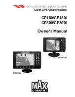
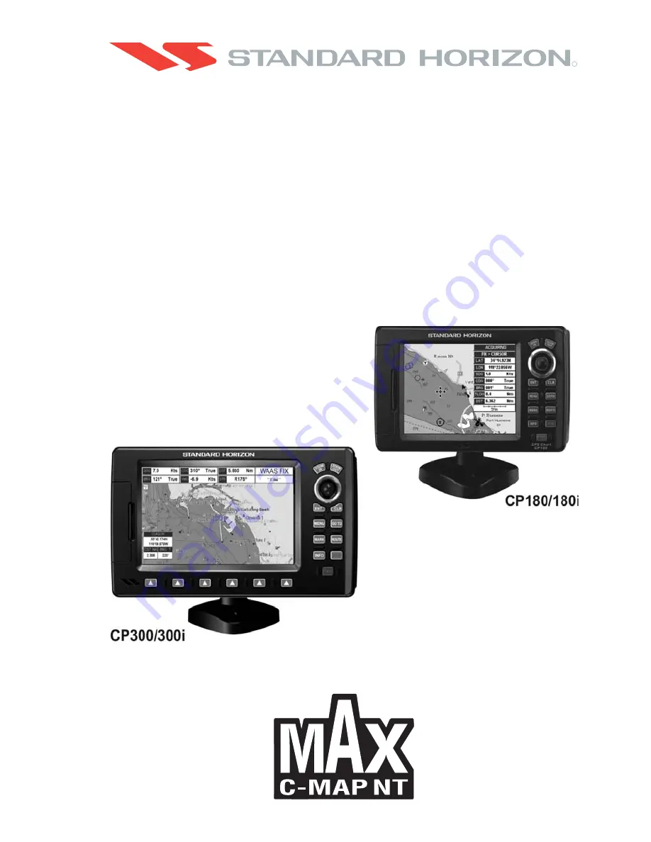
Page 1: ...CP180 CP180i CP300 CP300i Owner s Manual Color GPS Chart Plotters R ...

Page 2: ...aycauseharmfulinterference with radio communications There is no guarantee that interference will not occur in a particular instance If this equipment does cause harmful interference to other equipment try to correct the problem by relocating the equipment Consult an authorized STANDARD HORIZION dealer or other qualified service technician if the problem cannot be corrected Operation is subject to...

Page 3: ...hind a corner to move the tissue across the surface in overlapping side to side strokes If the tissue is too wet a noticeable wet film will be left in its path and you will need to repeat the process If too dry the tissue won t glide easily and may damage the surface CAUTION The GPS Chart Plotter is designed for maritime use To avoid water intrusion ensure the C MAP BY JEPPESEN C CARD door is comp...

Page 4: ...Page 6 GPS Chart Plotters R ...

Page 5: ...ONS 23 2 7 GPS POSITION ON A VHF RADIO 24 2 8 OPTIONAL BLACK BOX FISH FINDER 24 2 9 RADAR ANTENNA USA ONLY 24 2 10 PERSONAL COMPUTER CONNECTIONS 25 2 11 NMEA DATA PAGE 25 2 12 CP300 CP300i VIDEO INPUT 26 2 12 0 Video Camera Input 26 2 12 1 VCR or DVD Input 26 2 13 DEMO MODE For DEALER USE 28 3 CONTROLS AND INDICATORS 29 3 0 CONTROLS AND CONNECTIONS 29 3 0 0 The CP300 CP300i Soft Keys 30 3 1 GETTIN...

Page 6: ... 6 0 4 Dynamic Nav Aids 56 6 0 5 Safety Status Bar DSI Data Safety Indicator 56 6 0 6 Satellite Imagery 57 6 0 7 Currents Prediction 58 6 0 8 Chart Language 59 6 0 9 Pictures Diagrams 59 How to show the pictures or diagrams of a Multimedia Object 60 6 0 10 Enhanced Port Info 61 7 CREATING MARKS 63 7 0 CREATING A NEW MARK USING THE CHART PAGE 63 7 1 EDITING A MARK 63 7 1 0 Deleting a Mark or Waypoi...

Page 7: ...the User C CARD 84 12 PAGES 85 12 0 CHART PAGE 86 For CP300 CP300i Focus Soft Key on Dual Chart page 87 For CP180 CP180i Change Focus on Dual Chart page 87 Single Chart page 88 12 0 0 Window Selections 88 12 0 1 Customizing the Data Windows 88 12 0 2 Additional Functions on Chart page 90 12 0 3 Turning Off Information on Icon Points 90 12 0 4 Display Mode 90 12 0 5 Marine Settings 91 12 0 6 Depth ...

Page 8: ...0 2 Weather Forecast 112 15 0 3 Real Time View 112 15 0 4 Type of Data 112 16 MOBILARM 113 16 0 MOBILARM GPS CHART PLOTTER CONNECTION 113 16 1 SOFTWARE SETUP 114 16 2 MOBILARM STATUS 114 16 3 MOBILARM PTX 115 16 3 0MOBILARM MOB alert is received 115 16 4 PLACING CURSOR ON THE PTX ICON 116 16 4 0 Delete PTX 117 16 4 1 Goto PTX 117 16 4 2 The MOBILARM Alarm Status List 118 17 TROUBLESHOOTING 121 18 ...

Page 9: ...d impact resistant case with outstanding ergonomic design for effortless operation The advanced features of the GPS Chart Plotter include Direct sunlight viewable color LCD display CP180i CP300i Internal 50 Channel WAAS GPS Capable of using the Optional FF525 or FF520 50 200kHz BLACK BOX FISH FINDER Capable of using a RADAR Antenna USA ONLY C MAP BY JEPPESEN NT MAX cartography compatible Improved ...

Page 10: ...002222 Dust cover T9101553 Power data cable S8002223 Flush mounting screws CP180 ONLY EM016N550 Flush mount template CP180 ONLY Q7000619A GPS ANT Unit GSU 5H Series UX0GSU51SD CP180 ONLY EM022U106 Owner s Manual EM023U510 Quick Reference Guide NOTE is a revision number 1 1 1 CP300 CP300i Packing List PART CODE ITEM S8002224A External bracket S8002225 Mounting knob with two washers S8002235 Dust co...

Page 11: ...LY 600W 2 BronzeThru hull depth speed tempTransducer ACCESSORIES PARTS NAME ITEM Dua l Freq uency Fish Find er 1 3 RADAR UNIT SUPPLIED BY SI TEX USA The Radar antenna will be supplied by SI TEX in USA only and the part code is as follows MODEL NUMBER DESCRIPTION MDS 1 2kW 24 Mile 12 4 diameter Radome antenna MDS 8 2kW 24 Mile 20 diameter Radome antenna MDS 9 4kW 36 Mile 23 5 diameter Radome antenn...

Page 12: ...Page 14 GPS Chart Plotters R ...

Page 13: ...th the hardware for bracket mounting due to the internal design of the GPS antenna Below are pictures showing actual examples of the two types of installation NOTE The GPS Chart Plotter with internal GPS antenna is designed to be bracket mounted only Do not flush mount or GPS performance may be dramatically reduced or not receive a fix 2 1 BRACKET MOUNTING TheCP180 CP180iandCP300 CP300icanbemounte...

Page 14: ...ea of the cutout area that will allow the blade of a jig saw to be inserted Insert and cut out the area on the panel using the jig saw 3 Next drill the four holes required to insert the GPS Chart Plotter with the mounting studs 4 Install the mounting studs on the GPS Chart Plotter and insert into the mounting hole 5 Attach the GPS Chart Plotter to the mounting location by attaching the supplied ha...

Page 15: ... and spliced to ease installation Care must be taken when reconnecting the antenna cable to protect from water and corrosion 2 3 0 Flush mounting the antenna NOTE Before drilling holes it is recommended the antenna be positioned where the location is planned cable connected to the GPS Chart Plotter and power turned on to ensure a GPS Fix is received 1 Remove the threaded base from the antenna dome...

Page 16: ...he Yellow Brown or White wires 2 4 0 Connection Table For CP180 CP180i 12VDC Power and NMEA PWR ACC 1 Cable Pin Wire Color Description Connection Example Additional Comments 1 Black Battery Ground Connect to Battery Ground 2 Red Battery Positive Connect to Battery Positive 3 Green NMEA Common Common ground for NMEA devices 4 Blue Port1 Input Connect to Output of NMEA device Default is NMEA0183 5 B...

Page 17: ...tion Example Additional Comments 1 Black Battery Ground Connect to Battery Ground 2 Red Battery Positive Connect to Battery Positive 3 Green NMEA Common Common ground for NMEA devices 4 Blue Port 1 Input Connect to Output of NMEA device Default is NMEA0183 5 Brown Port 1 Output Connect to Input of NMEA device Default is NMEA0183 with GGA GLL RMC XTE DBT DPT MTW VHW sentences 6 Grey Port2 Input Con...

Page 18: ... and press ENT or move the ShuttlePoint knob to the right 5 Move the ShuttlePoint knob up down to select AIS 38400 and press ENT or move the ShuttlePoint knob to the right 6 Press CLR or move the ShuttlePoint knob to the left until the Chart page is shown Video Connector Pin Description Connection Example 1 Ground Connect to Video Signal Ground of DVD VCR Video Cameras 2 9 12 VDC Connect to Video ...

Page 19: ...iagram above you will notice Port2 Input and Output wires are shown in gray and not used AIS Setup The CP180 or CP180i has to be setup to be able to receive NMEA information from the AIS receiver 1 Press MENU movetheShuttlePointknobtohighlightSETUPMENUandpress ENT 2 Move the ShuttlePoint knob to highlight ADVANCED SETUP and press ENT or move the ShuttlePoint knob to the right 3 Move the ShuttlePoi...

Page 20: ...ectionaVideoCamera FF525 orFF520 AISreceiver VHFandAutopilot ACC 2 Cable Not used CP300 SMART GPS Antenna VIDEO Camera Battery 10 35Vdc Red 2A Fuse Black Switch VHF PILOT Green Blue Brown Gray White Yellow NMEA Common Port 1 Input Port 1 Output Port 2 Input Port 2 Output Port 3 Output PWR ACC 1 Cable AIS ...

Page 21: ...00 the Input Port operates at 38400 baud and the Output Port is disabled AIS Setup TheCP300orCP300ihastobesetuptobeabletoreceiveNMEAinformationfromtheAISreceiver 1 Press Menu move the ShuttlePoint knob to highlight SETUP MENU and press ENT 2 Move the ShuttlePoint knob to highlight ADVANCED SETUP and press ENT or move the ShuttlePoint knob to the right 3 Move the ShuttlePoint knob to highlight IN O...

Page 22: ...g to know the position of another vessel Other DSC VHF Manufactures GPS Chart Plotter Description VHF Green NMEA Common Ground Connect to NMEA Ground Brown NMEA Positive Output Connect to NMEA Input Blue NMEA Positive Input Connect to NMEA Output if available Some manufacturers of DSC VHF s are not capable of receiving NMEA DSC sentences from the GPS Chart Plotter Refer to the Owner s Manual and c...

Page 23: ...s ENT or move the ShuttlePoint knob to the right 3 Move the ShuttlePoint knob to highlight IN OUT CONNECTIONS and press ENT or move the ShuttlePoint knob to the right 4 Move the ShuttlePoint knob to highlight SEND REC RTE MARKS and press ENT or move the ShuttlePoint knob to the right to show the popup window 5 Move the ShuttlePoint knob to desired Port and press ENT The PC COM settings are Baud Ra...

Page 24: ...eo Input image can be shown on a window and placed over the Chart Navigation Highway Celestial and NMEA pages image at full screen NOTE If theVideoInputsignalsisnotdetected E g thevideocameraisnotconnectedtotheVideoInput connector the VIDEO INPUT menu item will be greyed out Video Connector Pin Description Connection Example 1 Ground Connect to Video Signal Ground of DVD VCR Video Cameras 2 9 12 V...

Page 25: ...hart Plotter page will be shown intermittently The intermittence time is selected by Switching Timeout item b SWITCHING TIMEOUT the possible choices are 5 10 30 sec 1 5 10 min Allows selecting the timing to change from Video Input and GPS Chart Plotter display c RESTORE DEFAULTS allows restoring the factory defaults for the Input picture adjustment When Restore default is executed the message OK i...

Page 26: ...nder Full page Radar page Navigation page Highway Page Celestial page NMEA Display page NOTE ThismodeisusebysellingdealerstopromotethefeaturesoftheGPSChartPlotterwhenonaretail shelf The Demo mode can be selected from the Simulation Menu following the procedure 1 Press MENU Move the ShuttlePoint knob to highlight SETUP MENU and press ENT 2 Move the ShuttlePoint knob to highlight ADVANCED SETUP and ...

Page 27: ...PESEN NT MAX C CARD must be purchased and installed The ShuttlePoint knob The ShuttlePoint knob moves the cursor about on the display screen quickly and accurately It also scrolls the desired option in the menu page s It changes the Chart Plotter from Home mode to Cursor mode on the chart screen For a detailed explanation of Cursor VS Home mode refer to Par 3 1 1 The ENT key Press ENT to select th...

Page 28: ...he CP300 CP300i Soft Keys The 6 keys in the bottom of the front panel hereinafter named Soft Keys have different functions associated depending on the software their labels are shown on the screen immediately above the keys the user can customize the function associated The Soft Keys These keys allow quick selection to the many pages the GPS Chart Plotter has These keys canbecustomizedtoyourprefer...

Page 29: ... hair appears this is called the cursor 5 When you move the ShuttlePoint knob you will notice DST and BRG values in the Data window change This shows the Distance and Bearing from the GPS Fix of your vessel to the position of the Cursor 6 If the cursor is moved to the edge of the screen the GPS Chart Plotter will automatically pan in the desired direction 3 1 1 Cursor Vs Home mode Cursor mode When...

Page 30: ...he ShuttlePoint knob to the right 4 The menu now shows two selections CHART and MENU which allows the Cursor Speed to be selected to High Medium or Low on Chart page or within the menus 5 With CHART or MENU selected press ENT or move the ShuttlePoint knob to the right Move the ShuttlePoint knob to the desired setting and press ENT or move the ShuttlePoint knob to the right 6 Press CLR until the me...

Page 31: ...th Up or Course Up The default selection is NORTH UP however you may want the top of the Chart page oriented so it will always show the area ahead of the direction your vessel is travelling which is called COURSE UP Figure 3 1 5 Course Up North Up menu 1 Press MENU Move the ShuttlePoint knob to highlight SETUP MENU and press ENT 2 Move the ShuttlePoint knob to highlight GENERAL SETUP and press ENT...

Page 32: ... 3 2 Adjusting Time The Time Setup menu allows the users to know the offset for the area and automatically changes the time in areas with Daylight Savings Figure 3 2a Time Setup menu NOTE By setting the time in the steps below the time shown on the celestial page is automatically set up 1 Press MENU Move the ShuttlePoint knob to highlight SETUP MENU and press ENT 2 Move the ShuttlePoint knob to hi...

Page 33: ...oint knob to highlight SETUP MENU and press ENT 2 Move the ShuttlePoint knob to highlight ADVANCED SETUP and press ENT or move the ShuttlePoint knob to the right 3 Move the ShuttlePoint knob to highlight NAVIGATE and press ENT or move the ShuttlePoint knob to the right 4 Move the ShuttlePoint knob to highlight COORDINATE SYSTEM and press ENT or move the ShuttlePoint knob to the right 5 Move the Sh...

Page 34: ...ek Finnish Russian Chinese Simplified The translations are included in Menu descriptions Soft Key labels and on Info Functions to ease operation See also Par 6 0 7 Set the language to be displayed on menus data pages warning alarm messages full quick info list of objects found by find nearest function and on charts such as place s names buoy s names and so on The selection now includes the capabil...

Page 35: ...catedundertheLCDontheCP300andCP300iareusedtoselectthepages quickly without the need to go into the menu The default pages are VIDEO NAV HIGHWAY CELESTIAL CHART and LIST When one of the Soft Keys is pressed popup windows above each Soft Key are shown with the key description Press the Soft Key with the desired page description and the GPS Chart Plotter will change to that page WAAS 3D WAAS 3D CHART...

Page 36: ... other selections that allow you to customize TIME SETUP Selects a sub menu to allow the time setup It is possible to choose the Time Zone select the Daylight Saving among On Off Auto and the Time Format switching 12 or 24 hours time format DATE FORMAT Allows choosing date format MM DD YY or DD MM YY COURSE UP NORTH UP Selections are North Up The Top of the page is fixed to North Course Up The top...

Page 37: ...ursor is moved over a buoy Mark or other item a popup window will show information of the item This menu item allows the window to be turned on or off CURSOR WINDOW By default when the cursor is moved a window is shown with the lat lon Distance and bearing from the vessels location to the cursor This selection allows the window to be turned off CURSOR POSITION Thepositionofthecursor vesselslocatio...

Page 38: ...Page 40 GPS Chart Plotters R ...

Page 39: ...light PORT SERVICES and press ENT or move the ShuttlePoint knob to the right 3 A popup window will be shown with a list of different Port Services In the table below is shown the list of the available Port Services Figure 4 0 0 Port Services Table 4 Move the ShuttlePoint knob to highlight the desired type of service and press ENT 5 Another popup window will appear displaying the distance and posit...

Page 40: ...CLR to show the actual position of the Port on the Chart page 7 Press CLR again at any time to return your cursor to your vessels position WAAS 3D Figure 4 0 1 Find a Port 4 0 2 Tide Stations This feature is used to locate Tide Stations nearest the position of your vessel Once a Tide Station is selected the Tide Graph can be used to determine Tide height and draught of the Tide based on a user spe...

Page 41: ...or 2 intheTideGraph 1 MovingtheShuttlePointknobtotheleftorrightchanges the time moving the ShuttlePoint knob up or down selects the Tide height and Tide draught on the Tide Graph NOTE The Local Offset matchs the Time Offset entered in the Time Setup menu see Par 3 2 4 0 3 Wrecks This feature is used to locate Wrecks nearest the position of your vessel A Wreck is represented with an icon on the cha...

Page 42: ...s nearest the position of your vessel An Obstruction is represented with an icon on the chart see the following table snag stump wellhead diffuser crib fish haven foul ground ice boom ground tackle foul area ICON DESCRIPTION F o u l Obstn 46 Obstn Wk Mast 1 2 Figure 4 0 4 Obstruction icons Table 1 Press INFO 2 Move the ShuttlePoint knob to highlight OBSTRUCTIONS and press ENT or move the ShuttlePo...

Page 43: ...o the right 3 A popup window will be shown with a list of Outdoor Recreational Area objects 4 Move the ShuttlePoint knob to highlight the desired object and press ENT 5 Another popup window will appear displaying the distance and position of the Lakes closest to your location 6 Using the ShuttlePoint knob highlight the desired Lake and press ENT This will show information on the Lake 7 Press CLR t...

Page 44: ...uick Info available services If you press ENT all available information about the cartographic point under the cursor will be shown See the next paragraph 4 0 5 1 Full Info On Lakes The following is an example of Full Info on Lakes Figure 4 0 5 1 Example of Full Info page To see the Fishing object press MENU when the Fishing object is highlighted On the screen appears ...

Page 45: ...sition of the Lake 5 Press ENT to show the actual position of the Lake on the Chart page 6 Press CLR twice to return your cursor to your vessels position 4 0 7 Points Of Interest This feature is used to locate Points Of Interest nearest the position of your vessel 1 Press INFO 2 Move the ShuttlePoint knob to highlight POINTS OF INTEREST and press ENT or move the ShuttlePoint knob to the right 3 A ...

Page 46: ...TS and press ENT or move the ShuttlePoint knob to the right 3 The Select Name popup window will appear This window will allow you to enter in the name of the User Point you wish to locate 4 Move the ShuttlePoint knob up down to change each number or letter and left right to move to the next or previous position in the name of the Mark 5 Once the name of the desired Mark reads in the Select Name wi...

Page 47: ...r cursor to your vessels position WAAS 3D INFORMATION Figure 4 0 9 Find GPS Coordinates 4 0 10 Information This feature allows you to obtain information on any position on the chart page 1 Press INFO 2 Move the ShuttlePoint knob to highlight INFORMATION and press ENT or move the ShuttlePoint knob to the right 3 A page will be shown with objects information The upper side of the page contains the I...

Page 48: ...Page 50 GPS Chart Plotters R ...

Page 49: ...technology Key points are Data Features ISO Certification electronic chart production process with quality certification Extra Large Coverage all the C Map electronic chart detail and a huge coverage without having to change cartridge Official data source data based on use of official data sources Hydrographic Offices Release Detailed World Background worldwide background chart with details Depths...

Page 50: ... Type Font improves text on chart for optimal reading Presentation Features Clear View advanced legibility techniques providing more chart data on the screen Clear Info sophisticated Human Dictionary to translate Nav Aid abbreviations found on paper charts Flexi Zoom increased Under and Over Zoom between chart levels resulting in optimal scale display for any situation Perspective View Real World ...

Page 51: ...ax Functions menu is described in the following 6 0 0 Zoom Type Zoom Type refers to the chart scale selection It has two options Standard default or Flexi Zoom When Zoom Type is set to Flexi Zoom a short ZOOM IN ZOOM OUT push causes a change of chart level while a long ZOOMIN ZOOMOUT push press and hold causes an expansion or compression of the chart image without a chart level change CHART US NOS...

Page 52: ...s CLR until the menu disappears or an easier method is to move the ShuttlePoint knob to the left a few times 6 0 1 Icons Size On MAX charts it is possible to set the size of all icons drawn on the charts selecting between Standard and Large size ICONS SIZE standard ICONS SIZE large Figure 6 0 1 Icons Size To activate this function follow the procedure 1 Press MENU Move the ShuttlePoint knob to hig...

Page 53: ...mal mode during navigation Perspective view of the chart is a type of bird s eye view of a chart and give you a more realistic perspective of the chart As the upper side of the map is more compressed than the lower side a wider map area is visible so it allows showing more chart information immediately ahead and around the cursor Perspective View ON Perspective View OFF Figure 6 0 3 Perspective Vi...

Page 54: ...arning or alarm condition is identified by the red color to indicate possible risk To activate this function follow the procedure 1 Press MENU Move the ShuttlePoint knob to highlight SETUP MENU and press ENT 2 Move the ShuttlePoint knob to highlight MAX FUNCTIONS and press ENT or move the ShuttlePoint knob to the right 3 Move the ShuttlePoint knob to highlight SAFETY STATUS BAR and press ENT or mo...

Page 55: ...lities Pingos and Production installations Red when Guardian Technology detects cautionary or restricted area Safety Status Bar O ZOOM DANGERS CAUTIONS BEST MAP DATA OFF DECLUT Figure 6 0 5 Safety Status Bar 6 0 6 Satellite Imagery This function allows to overlay the Satellite image for background map When it is set On the Palette is set to Normal to display the proper colors NOTE The satellite im...

Page 56: ...e strength of the current as follows 0 to 0 1 kn 0 2 to 1 0 kn 1 1 to 2 0 kn 2 1 to 3 0 kn 3 1 to 9 9 kn Yellow Yellow Orange Orange Red Figure 6 0 7a Tidal stream arrows table When the GPS Chart Plotter receives a valid position fix the Tide icons are shown on the charts on the basis of the current date and time the screen displays and changes arrows as date time changes It is possible to see the...

Page 57: ...ographic data data cartridge or embedded charts Mode Defines how objects are translated Selections are Off Enables the language chosen in the Language menu above If the selected language is not present on the objects information English is used English Always uses English Local Uses the Local language present on C MAP BY JEPPESEN C CARD If no Local language is available English is used 4 After the...

Page 58: ...he window WAAS 3D Figure 6 0 9b Example of Quick Info on camera icon on CP300 CP300i On the CP300 CP300i press IMAGE or on the CP180 CP180i press ENT for 1 second to display the image on the screen Figure 6 0 9c Example of displayed image on CP300 CP300i Otherwise on the CP300 CP300i press EXPAND or on the CP180 CP180i press ENT to open the Full Info on the object Note that on the Full Info there ...

Page 59: ...any by moving the ShuttlePoint knob left or right 6 0 10 Enhanced Port Info Optional C MAP BY JEPPESEN MAX C Cards include additional Port Services that were not present before Additional attributes of Port Areas and Port Marinas have been included as Location Country Region State Harbour master telephone number etc see the following figure PORT icon 1 1 WAAS 3D Figure 6 0 10 Example of enhanced P...

Page 60: ...Page 62 GPS Chart Plotters R ...

Page 61: ... placed under the location of the cursor and a popup window is shown with the exact Lat Lon of the Mark 3 If the position is incorrect on the CP180 CP180i press ENT select EDIT using the ShuttlePoint knob and press ENT On the CP300 CP300i press EDIT that will allow you to change the position Mark name and icon type Vessel location Mark placed under Cursor Lat Lon of Mark DST BRG from vessel locati...

Page 62: ... select the Lat Lon and press ENT 9 Move the ShuttlePoint knob up or down to select the first character 10 Move the ShuttlePoint knob to the right to select the next character 11 Repeat steps 9 and 10 until the desired position is shown Press ENT and CLR to store the Mark 7 1 0 Deleting a Mark or Waypoint 1 Move the ShuttlePoint knob over the Mark or Waypoint to delete 2 On the CP180 CP180i press ...

Page 63: ...ing or descending order NEW MARK Allows you to create and edit a new Mark Useful when entering many Marks from a list MODE This selection controls how the Marks or Waypoints are shown on the Chart page Selections are a SHOW icon and name are shown b ICON only icon no name is shown c HIDE Mark or Waypoint is hidden d SHOW ALL All Marks or Waypoints are shown e ICON ALL All Icons are shown without n...

Page 64: ...ve the ShuttlePoint knob to highlight the desired Icon and press ENT 7 Move the ShuttlePoint knob to the right to select the Mark name Press ENT and the first digit in the name will be highlighted 8 Move the ShuttlePoint knob up or down to select the first character 9 Move the ShuttlePoint knob to the right to select the next character 10 Repeat steps 8 and 9 until the Mark name is shown Press ENT...

Page 65: ...GOTO popup window will be shown Figure 7 4 GO TO menu 1 3 Move the ShuttlePoint knob to highlight CURSOR and press ENT Figure 7 4a GO TO menu 2 4 The GPS Chart Plotter is now navigating from your current position to the location selected at step 1 A bearing line between the vessels location and the destination point is shown A popup window shows the Distance DST and Bearing BRG from the vessels lo...

Page 66: ...ve the cursor over the designed Waypoint and press GOTO For more information about Routes refer to Section 9 GOTO MARK 1 Move the ShuttlePoint knob to an open position no buoy warning etc under the cursor on the Chart page 2 Press GOTO to show the GOTO popup window 3 Move the ShuttlePoint knob to highlight MARK and press ENT to show the MARKS WAYPOINTS List 4 Move the ShuttlePoint to the highlight...

Page 67: ...o the point 2 You will notice a MOB Mark will be on the Chart page and all navigation is referring back to this point 3 On the CP300 CP300i If the cursor is moved over the MOB Icon the popup windows over Soft Keys will be shown allowing quick access to the Navigation or Highway pages Figure 8 0 MOB point 8 1 DELETING A MOB POINT 1 Move the ShuttlePoint knob until the cursor is over the top of the ...

Page 68: ...Page 70 GPS Chart Plotters R ...

Page 69: ...oute 4 Press ROUTE You will notice another Waypoint is shown under the cursor and a line joins the starting Waypoint to the Second Waypoint Figure 9 0 Creating a Route using Waypoints 5 Repeat steps 3 and 4 until all Waypoints are entered into the Route NOTE At this point the Route is saved as ROUTE01 If you would like to save the Route under a specific name follow the next steps 9 1 CHANGING NAME...

Page 70: ... Waypoint will be placed under the cursor 3 Move the ShuttlePoint knob to the second Lat Lon of the next leg in the Route 4 Press ROUTE Another Waypoint is shown under the cursor and a line joins the starting Waypoint to the second Waypoint 5 Repeat steps 3 and 4 until all Waypoints are entered into the Route Figure 9 2 Olympic Route creation 1 6 Then move the ShuttlePoint knob to the last Waypoin...

Page 71: ...ntil the cursor is over the Mark that you want to be the next leg in the Route 3 Press ROUTE You will notice a bearing line joins the first and second Mark which means these Marks are selected into the Route 4 Repeat steps 3 and 4 until all Marks are entered into the Route NOTE At this point the Route is saved as ROUTE01 If you would like to save the Route under a specific name follow the remainin...

Page 72: ...ft side of the above picture Once you have positioned the cursor at the location you want press ENT see the right side of the above picture Figure 9 5a Inserting Waypoint procedure 2 9 6 GOTO A ROUTE 9 6 0 By select Route 1 Move the ShuttlePoint knob to an open position no buoy warning etc under the cursor on the Chart page 2 Press GOTO to show the GOTO popup window 3 Move the ShuttlePoint knob to...

Page 73: ...o confirm Move the ShuttlePoint knob to highlight YES and press ENT The Route has been deleted WARNING An active Route one that you are navigating to cannot be deleted until you stop navigating to the Route 9 8 OTHER SETTINGS IN ROUTE MENU You will notice the ROUTE menu has other selections SELECT Choose an available Route to create or choose a stored Route to show and follow on the Chart page REV...

Page 74: ...ected the function returns the list of dangerous objects and the relative dangerous Route leg that is drawn with a different color Route legs which were classified as dangerous are displayed in RED It means that there is at least one dangerous object in the vicinity of this leg and it has been found Route legs which were classified as safe are displayed in GREEN It means that the data was checked ...

Page 75: ...s 10FT ACCURACY Defines a segment length into which a leg of the Route is divided in order to execute the search for dangerous objects with better accuracy When accuracy is maximal a segment length is the shortest When accuracy is minimal a segment length is the longest Selects among Minimum Low Medium High and Maximum See the picture below The default setting is Medium ROUTE CHECK REPORT Shows th...

Page 76: ...Page 78 GPS Chart Plotters R ...

Page 77: ...the ShuttlePoint knob to highlight TRACK and press ENT 3 Move the ShuttlePoint knob to highlight STEP UNIT and press ENT or move the ShuttlePoint knob to the right 4 Move the ShuttlePoint knob to highlight Dist or Time and press ENT or move the ShuttlePoint knob to the right Figure 10 Distance Units and Time Units 5 Move the ShuttlePoint knob to highlight DISTANCE or TIME step interval and press E...

Page 78: ...r off the tracking function ACTIVE TRACK This selection allows you to save a Track to one of the 5 Tracks available VISIBLE Shows or hides a Track shown in ACTIVE TRACK menu LINE COLOR Selects the color of the Track line DELETE Deletes a Track selected in the ACTIVE TRACK menu STEP UNIT Allowable selection are Distance or Time DISTANCE User adjustable Distance interval of when Track point is laid ...

Page 79: ...ghted it will be shown in a yellow frame 2 Move the ShuttlePoint knob to highlight the Trip Log window TLOG and press ENT 3 A popup window will be shown Move the ShuttlePoint knob to TLOG and press ENT 4 Another popup window will be shown Move the ShuttlePoint knob to RESET and press ENT 5 A warning popup window will be shown to confirm if you want to reset the Trip Log Move the ShuttlePoint knob ...

Page 80: ...Page 82 GPS Chart Plotters R ...

Page 81: ...rack history to the optional User C CARD 1 2 3 4 5 6 Type of data contained in the file Mark file Waypoint file File name Number of Selected file Information on stored User Points on Internal Memory Time of file creation Date of file creation 4 5 2 1 3 6 Figure 11 0 User C CARD Menu 11 0 0 Formatting the User C CARD 1 Press MENU MovetheShuttlePointknobtohighlightUSERPOINTSandpress ENT 2 Move the S...

Page 82: ...rom the User C CARD list by using the ShuttlePoint knob and press ENT 4 Move the ShuttlePoint knob to the left to highlight LOAD and press ENT 5 A popup information window will appear when loading is complete 6 Press ENT to confirm 11 0 3 Deleting a file from the User C CARD You may want to delete a saved file on the User C CARD 1 Press MENU Move the ShuttlePoint knob to highlight USER POINTS and ...

Page 83: ...ample with RADAR connected WAAS 3D WAAS 3D WAAS 3D WAAS 3D Figure 12 Screen display pages example The pages can selected in the following way Selection by MENU This function is available on the CP180 CP180i and CP300 CP300i 1 Press MENU The following page is shown on the screen Figure 12a Main Menu on CP180 CP180i Figure 12b Main Menu on CP300 CP300i 2 Move the ShuttlePoint knob to highlight the d...

Page 84: ... etc The GPS Chart Plotter is provided with a Worldwide background showing C MAP BY JEPPESEN NT MAX detail up to 2 0 NM For more detail optional C MAP BY JEPPESEN NT MAX C CARDs are used It is possible to set the chart as a single or two charts side by side 1 Press MENU Move the ShuttlePoint knob to highlight CHART and press ENT Two Chart page types are available Single and Dual 2 Move the Shuttle...

Page 85: ...appears where the active focus window label is highlighted Figure 12 0b Example of Dual Chart page with FOCUS window shown 3 Move the ShuttlePoint knob up and down to highlight the desired item and press ENT The red boarder is moved to the focused window For CP180 CP180i Change Focus on Dual Chart page When the Dual Chart page has been selected the active window is highlighted by a red boarder aro...

Page 86: ...ALL HIGHWAY COMPASS WAAS WAAS 3D Figure 12 0 0 Data window layout 1 To change press MENU Move the ShuttlePoint knob to highlight SETUP MENU and press ENT 2 Move the ShuttlePoint knob to highlight GENERAL SETUP and press ENT or move the ShuttlePoint knob to the right 3 Move the ShuttlePoint knob to highlight WINDOW SETUP and press ENT or move the ShuttlePoint knob to the right 4 Move the ShuttlePoi...

Page 87: ...ated Time of Arrival TRACKING Tracking SCALE Chart Scale GPS Status Shows GPS Fix Status WAAS 3D 2D To select the desired field follow the procedure 1 Press and hold MENU until a field is highlighted it will be shown in a yellow frame 2 Move the ShuttlePoint knob to the desired data field the yellow frame is moved to the desired data field and press ENT The popup window will be shown 3 MovetheShut...

Page 88: ...Point knob to the right 5 Press CLR or move the ShuttlePoint knob to the left until the Chart page appears AUTO INFO Off AUTO INFO On Points AUTO INFO On All Figure 12 0 3 Example of Auto Info settings 12 0 4 Display Mode Selects from a pre defined table what cartographic objects are displayed and which display options are set Pre programmed settings are user selectable from Full Medium Low Radar ...

Page 89: ...ns Icon Depth Icon Icon Icon Icon Icon Diffusers Icon Depth Icon Icon Icon Icon Icon Wrecks Icon Depth Icon Icon Icon Icon Icon 12 0 5 Marine Settings To control the display on the map of the marine features Place Names Turns the Local area names On or Off Names Tags Turns a tag for particular chart objects that either includes the Name of the chart object or the Depth of an Underwater chart objec...

Page 90: ...cranes Tracks Routes Turns displaying of underwater objects On or Off Objects are obstructions wrecks cable etc 12 0 6 Depth Settings To control the display on the map of the depth informations Depth Range Min Sets the minimum depth limit to show Depth Sounding Bathymetric Lines and Depth Area The default setting is 0FT Depth Range Max Sets the max depth limit to show Depth Sounding Bathymetric Li...

Page 91: ...stline Each box indicates an area where more detail is available The Chart Boundaries are only show when a C MAP BY JEPPESEN NT NT or MAX CARD is inserted into the GPS Chart Plotter See the figure below Chart Boundaries ON Chart Boundaries OFF Value Added Data Turns the displaying of Value added data On or Off The Value Added Data VAD is a collection of additional cartographic objects which are no...

Page 92: ...rage 12 0 9 Underwater Objects Settings To control the display on the map of the Underwater Objects features Underwater Object Limit SelectsthemaxdepthvaluetodisplayUnderwaterObjects Ifvalueissetto0FT theUnderwater Objectsarenotshownonthecharts Menuoptionsaregreyedout Ifvalueismorethan0FT i e 10FT in the Range from 0FT to the selected value the Underwater Objects are displayed according to their s...

Page 93: ... SETUP and press ENT or move the ShuttlePoint knob to the right 3 Move the ShuttlePoint knob to highlight WINDOW SETUP and press ENT and press ENT or move the ShuttlePoint knob to the right 4 Move the ShuttlePoint knob to highlight NAVIGATION PAGE and press ENT and press ENT or move the ShuttlePoint knob to the right 5 Move the ShuttlePoint up or down to select COMPASS TAPE and press ENT 6 Press C...

Page 94: ...age contains Tide information critical for safe navigation This page is also useful for boaters that are concerned about the height of the water under a bridge or by fisherman that wish to know the tide and moon phase of a specific date Changing date 1 Press ENT and a popup window will be shown 2 Moving the ShuttlePoint knob up or down changes the digits and left and right selects the month day an...

Page 95: ... used Satellite Used Satellite 1 6 3 Vertical Dilution of Precision WAAS GPS Icon Date and Time 5 1 4 6 2 5 3 5 6 Used Satellite 6 COG Course Over Ground 7 D C E A B 7 14 20 25 31 28 Figure 12 5 GPS Status page The WAAS GPS Icon area may change due to the satellite reception ACQUIRING the GPS is trying to receive a valid position fix GPS2D The GPS is receiving at least 2 valid Satellites GPS3D the...

Page 96: ...lePoint knob to highlight the preferred item and press ENT 4 Press CLR until the menu disappears or an easier method is to move the ShuttlePoint knob to the left until the menu disappears 12 6 NMEA DISPLAY PAGE The GPS Chart Plotter is capable of displaying information in the customizable data windows from external NMEA devices Depth sounder Speed Log with temp Wind speed and direction Flux gate c...

Page 97: ... GPS Chart Plotter This page can also be used to see if the GPS Chart Plotter NMEA output is being loaded down by a external NMEA device the GPS Chart Plotter is connected to Scenario VHF Radio connected but the Radio is not receiving a GPS Position Usually the VHF Radio will be connected to the Green and Brown wires To check to see if the GPS Chart Plotter is transmitting the sentences 1 Press ME...

Page 98: ...tter is connected to the Optional FF525 or FF520 50 200kHz BLACK BOX FISH FINDER or a Digital Depth Sounder Wind Speed Direction Speed Log with Temp with NMEA output the GPS Chart Plotter is capable of show Trends in the data from the device To select a NMEA Trend page 1 Press MENU Move the ShuttlePoint knob to highlight NMEA DISPLAY and press ENT Figure 12 8 NMEA Display menu on CP300 CP300i 2 Mo...

Page 99: ...ION Send calls to or from another vessel equipped with a DSC transceiver STANDARD HORIZON VHF Marine Radios with Digital Selective Calling are able to be interfaced with the GPS Chart Plotter which feeds GPS data to the VHF and listens for DSC callsfromtheVHF ByconnectingafewwiresbetweentheSTANDARDHORIZONVHFand the GPS Chart Plotter it will receive 1 a vessel that has transmitted a DSC Distress ca...

Page 100: ...d also prompts the user to see the location of the Vessel in Distress and also allows for easy navigation to the vessel 12 9 2 Position Request STANDARD HORIZON VHF radios can transmit a DSC call to other equipped Vessels with a DSC VHF or request this radio transmit the GPS position When this position is received the STANDARD HORIZON VHF radio sends the information to the GPS Chart Plotter which ...

Page 101: ...ut wires are set to SI TEX proprietary Radar sentences This means other devices should not be connected to the Input or Output wires 13 1 NAVIGATE The Navigate menu allows customization of the Coordinate System Loran TD s Map Datum Map Orientation Resolution angle the vessel has to change before the chart is redrawn and Static Navigation See the following table Coordinate System Selections are a T...

Page 102: ... displayed is roughly not correct 13 2 COMPASS The GPS Chart Plotter computes compass direction from the constellation of GPS Satellites For the GPS Chart Plotter to compute direction the vessel must be moving through the water This menu allows the GPS Chart Plotter to customize the following selections Bearings Selects between True and Magnetic When Magnetic bearings is enabled the GPS Chart Plot...

Page 103: ...ycle the same objects are found again the alarm window will not be shown Instead if in the next searches the objects found before are no longer detected their relevant item in the Grounding Alarm Report page is cleared note that in this case if the same object type is found again later the Alarm will be shown The GPS Chart Plotter shows an icon on the charts that identifies when a Grounding Alarm ...

Page 104: ...at are stored in the GPS Chart Plotter s memory 7 Highlight the desired Route and press ENT 8 Move the ShuttlePoint knob to highlight SPEED and press ENT 9 Enter in the speed you want to vessel to travel at in simulation mode by moving the ShuttlePoint knob left or right to select a number and up or down to change a number 10 When the speed is adjusted press ENT 11 Press CLR multiple times until t...

Page 105: ...ased on your vessel s speed and direction and the target s speed and direction CPA Limit This is the distance from your vessel that a target may reach before a target is deemed a threat CPA Alarm Occurs if CPA is less or equal to CPA Limit This test is done for active targets only TCPA Time to closest Point of Approach is the time remaining until the CPA will occur TCPA Limit This is the time rema...

Page 106: ...vation Range Defines the range from the fix within which the AIS Target becomes active The values allowed are from 0 1 to 20NM The default setting is 5NM CPA Alarm Turns On or Off the alarm The default setting is On CPA Limit The values allowed are from 0 1 to 10NM The default setting is 0 5NM TCPA Alarm Turns On or Off the alarm The default setting is On TCPA Limit The values allowed are from 1 t...

Page 107: ...is surrounded by a square frame when user places the cursor over the icon 14 4 AIS LIST It is possible to show the AIS List page that show basic information of the Target ship with the ability to select a Target ship and locate it on the chart Follow the procedure 1 Press MENU MovetheShuttlePointknobtohighlightUSERPOINTSandpress ENT 2 Move the ShuttlePoint knob to highlight AIS LIST and press ENT ...

Page 108: ...Page 110 GPS Chart Plotters R ...

Page 109: ...d direction ground temperature level of humidity visibility in miles WIND Speed Dir 0 WAVE Height Dir 1 TEMPERATURE 18 HUMIDITY 30 VISIBILITY 20 WEATHER TYPE Sun WEATHER TYPE Rain WEATHER TYPE Fog WEATHER TYPE Snow WEATHER TYPE Clouds WEATHER TYPE Partly Cloudy WEATHER TYPE Thunderstorm Data Type Display Figure 15 Weather data package 15 0 C WEATHER SERVICE MENU To select the menu 1 Press MENU Mov...

Page 110: ... 15 0 1 Copy From User C CARD Allows the whole data package C Weather loading from the User C CARD 15 0 2 Weather Forecast Allows selecting the Layer of specific weather data to be displayed on the screen and to change date and time of the forecast preview The following functions are available Panning default usage of the cursor key is the normal panning function Zoom in out zoom in out functions ...

Page 111: ...vessels position is shown on the Standard Horizon GPS Chart Plotter 16 0 MOBILARM GPS CHART PLOTTER CONNECTION Connect the MOBILARM system to one of the Ports on the Standard Horizon GPS Chart Plotter Refer to Par 2 4 0 Connection Table for CP180 CP180i Par 2 4 1 Connection Table for CP300 CP300i and MOBILARM Owner s Manuals for connections Connection Example Blue Brown Black Green Red PWR ACC 1 C...

Page 112: ...e right 6 Move the ShuttlePoint knob up down to select MOBILARM and press ENT or move the ShuttlePoint knob to the right Selecting MOBILARM format activates the function 7 Press CLR or move the ShuttlePoint knob to the left until the Chart page is shown The GPS Chart Plotter continuously verifies the communication status with MOBILARM PTX Personal Transponder device When a signal from the PTX is l...

Page 113: ...ILARM PTX A PTX is the Personal Transponder device that is worn by the crew If a crew member falls in the water the MOBILARM sends a signal to the GPS Chart Plotter which creates and displays a PTX icon on the Chart page 16 3 0 MOBILARM MOB alert is received When crew member falls in the water the MOBILARM sends a signal to the GPS Chart Plotter which creates and displays a PTX MOB icon on the Cha...

Page 114: ...tive one the user must confirm to navigate to it b If the received PTX is the active one navigation data is updated The PTX icon appears at the new position and a popup warning window appears 16 4 PLACING CURSOR ON THE PTX ICON Moving the ShuttlePoint knob so the cursor is over the PTX icon on the Chart page will show an information window and allow you to Goto the location of the PTX delete the P...

Page 115: ...cted on the GPS Chart Plotter navigation will start to the PTX icon location After the GPS Chart Plotter has received a PTX MOB alarm using the ShuttlePoint knob move the cursor over the PTX to navigate to and then ON CP180 CP180i press ENT select GOTO using the ShuttlePoint knob and press ENT Figure 16 4 1 Example of Goto PTX on CP180 CP180i ON CP300 CP300i two Soft Keys under the display will be...

Page 116: ...s the list of all PTX that the GPS Chart Plotter has received an alarm from To review the page 1 Select the Chart page 2 Press MENU to show the Main menu 3 Move the ShuttlePoint knob to highlight USER POINTS and press ENT 4 Move the ShuttlePoint knob to highlight MOBILARM and press ENT 03 45 14 PM 10 31 24 PM 213 22 120W 305 04 015W 20 01 022N 79 56 320N PTX number PTX position Time the PTX alarm ...

Page 117: ... the selected PTX Once the navigation has been activated close all menus data pages if open and center the chart selected PTX DELETE Deletes the selected PTX SHOW Centers the chart on the selected PTX SHOW ALL Selects the best chart scale to see PTX icons on the map at the same time ...

Page 118: ...Page 120 GPS Chart Plotters R ...

Page 119: ...t The internal temperature is very high Control the contrast Protect the GPS Chart Plotter from direct sunlight The GPS Chart Plotter does not respond to any command The GPS Chart Plotter may be in an unpredictable status Try to turn Off and then turn On If the problem persists reset the RAM or remove power from the battery The location of my fix is not shown correctly on the Chart page Please rep...

Page 120: ...Page 122 GPS Chart Plotters R ...

Page 121: ...Plotter 18 0 0 RAM Menu reset This test verifies the integrity of the memories and if desired during this test all the internal memory can be erased and the default setting restored RAM Clear To clear internal memory If the GPS Chart Plotter exhibits unusual operations or appears to be malfunctioning it may be possible to correct the problem by clearing RAM This operation will erase all Marks Rout...

Page 122: ...nal Source between PORT 1 PORT 2 PORT 3 PORT4 and PORT 5 ONLY FOR CP300 CP300I the Baud Rate between 300 1200 2400 4800 9600 38400 115200 the Data Bits Word Length between 7 or 8 the Parity between even odd or none the Stop Bits between 1 or 2 Default settings are Port PORT 2 Baud Rate 4800 Data Bits 8 Parity none Stop Bits 1 Input Data Display To allow the GPS Chart Plotter to act as a computer t...

Page 123: ...C MAP BY JEPPESEN NT MAX C CARD Operating temperature range 32 F 131 F 0 C 55 C Storage temperature 4 F 158 F 20 C 70 C Water Resistance splash proof Memory Permanent Keyboard Silicon rubber backlight Weight without bracket 1 322 lb 600 g User Points Marks Waypoints 3000 Routes 50 max 100 Waypoints each Track Points 10000 recordable in 20 Tracks NMEA Output sentences GLL VTG BWC WCV APA APB HTG BO...

Page 124: ...C Water Resistance splash proof Memory Permanent Keyboard Silicon rubber backlight Weight without bracket 2 028 lb 920 g User Points Marks Waypoints 3000 Routes 50 max 100 Waypoints each Track Points 10000 recordable in 20 Tracks NMEA Output sentences GLL VTG BWC WCV APA APB HTG BOD XTE RMA RMB RMC GGA HSC DBT DPT MTW VHW WPL RTE NMEA Input sentences BWC DSC DSE GGA GLL GSA GSV HDG HDM HDT RMC VHW...

Page 125: ... 97mm in diameter x 32mm in height flush mounted or 61 5mm on flag pole mount Weight without cable 0 35 lb 160 g Cable white 15 meter 8x28AWG cable with 6 pins female connector Electrical Characteristics Input Voltage 10 Vdc to 35 Vdc unregulated Input Current 0 8 Wmax GPS Receiver Sensitivity Tracking Navigation 160 dBm Acquisition Reacquisition 160 dBm Cold Starts 145 dBm GPS Performance GNSS Sy...

Page 126: ...Page 128 GPS Chart Plotters R ...

Page 127: ...line and the bottom of the hull keel Draught determines the minimum depth of water a ship or boat can safely navigate On the Celestial page the draught window shows the height of the tidal water during a 24hr period of time This height is dependant on the time of day selected using the ShuttlePoint knob DSC Digital Selective Calling Digital Selective Calling is a semi automated method of establish...

Page 128: ...he True Wind Speed when an external wind instrument with NMEA is connected TTG Time To Go Shows time to go to reach a Destination point UNITS Nm Nautical Mile 1 NM 1 15 Sm or 1 85Km Sm Statue Mile 1Sm 0 87Nm or 1 61Km Km Kilometer 1 Kilometer 0062 Sm or 0 54Nm FT Feet 1 Foot 0 167 Fathoms or 0 305 Meters FA Fathom 1 Fathom 6 Feet or 1 83 Meters Mt Meter 1 Meter 3 28 Feet or 0 55 Fathoms Kts Knot 1...

Page 129: ...P Shows the sea water temperature when the FF525 50 200kHz BLACK BOX FISH FINDER or a Digital Speed Log Temp instrument with NMEA is connected XTE Cross Track Error The distance your vessel is off course left or right to a Destination point ...

Page 130: ...Page 132 GPS Chart Plotters R ...

Page 131: ...reas 91 Audible Alarm 105 Auto Info 39 106 Auto Position 106 Auto Switch 27 Automatic Route Check 76 Autopilot 19 21 22 24 AWD 89 AWS 89 B back up 83 background 11 29 86 Backlight 30 33 123 Bathymetric 51 Bathymetric Lines 92 BATTERY CONNECTIONS 23 Beacon 91 Bearing 89 129 Bearings 104 BOD 125 126 Bracket installation 15 BRACKET MOUNTING 15 BRG 89 129 brightness 123 Buoy 90 91 BWC 98 125 126 C C C...

Page 132: ...OR POSITION 39 CURSOR SPEED 39 Cursor Speed menu 32 CURSOR WINDOW 39 Custom 90 customize data fields 29 Customizing the Data Windows 88 D dangerous objects 76 dangerous Route leg 76 Dangerous Target 107 Data Features 51 data fields 11 88 Data Safety Indicator 94 Data window layout 88 DATE 89 129 Date 96 105 DATE FORMAT 38 Daylight Saving 38 daylight savings time 34 DBT 98 125 126 DC Power Connecti...

Page 133: ... 38 103 FISH FINDER 200kHz 38 FISH FINDER 200kHz CHART 38 FISH FINDER 50 200kHz 38 FISH FINDER 50kHz 38 FISH FINDER 50kHz CHART 38 Fishing Facility 76 Fix Status 89 Flexi Zoom 52 53 Flush installation 16 FLUSH MOUNTING 16 Flush mounting 17 Flux gate compass 98 Focus 87 forecast 111 Format User C CARD 83 FT Feet 130 Full Info On Lakes 46 Full Screen View 27 G GENERAL SETUP menu 38 General Window 88...

Page 134: ...11 Loading a file 84 Local area names 91 LOCATE 65 Longitude 35 93 Loop Back Test 124 Loran TD 35 104 Lost Target 107 LOW WATER 130 M Magnetic bearings 104 Main Menu 29 85 Map Datum 103 Map Functions Menu 53 Map Orientation Resolution 103 Marine Settings 91 MARK 30 Mark 11 30 48 63 64 65 66 67 68 71 73 83 125 126 Mark creation 63 Mark editing 63 MARKS WAYPOINTS 38 Marks Waypoints List 66 MEASURE D...

Page 135: ... 54 PLACING A MOB 69 Points Of Interest 47 91 92 polarity 121 Port 42 90 Port Info 52 61 Port Plan 52 Port Services 41 Ports Services 91 92 Position Request 101 102 130 POSITION Send 101 Power Consumption 125 126 Power On 30 Power supply 125 126 Presentation Features 52 Production Installation 76 PTX 115 PTX icon 115 PTX information 116 PTX List page 118 PTX warning window 115 116 PWR 30 Q QUICK I...

Page 136: ...og 24 98 100 Speed Over Ground 89 Spot Soundings 51 Standard Zoom Type 53 Standard Zoom 53 start a new Track 80 start navigating 29 Start Up page 31 Static Navigation 104 STEER 130 Steering 89 STOP Navigation 68 STR 89 Sunlight 36 39 121 SWITCHING TIMEOUT 27 System Test 123 T Target 107 TCPA 107 TCPA Alarm 107 108 TCPA Limit 107 108 TD 35 103 104 Temp 89 TEMP TREND 38 temperature 38 125 126 TERMS ...

Page 137: ... 26 Video Input 11 26 38 Video port 26 VideoCamera 22 VISIBLE track 80 VMG 89 130 voltage 121 VTG 98 125 126 VWR 98 125 126 VWT 98 125 126 W WAAS 16 89 97 121 127 130 WAAS 2D 3D 97 130 WAAS GPS antenna 16 121 WARNING 4 Warning alarm Icon 56 Warping Facility 76 warranty 11 Water Resistance 125 126 WATER TEMP 131 Water Temperature 89 Waypoint 30 63 64 65 68 71 125 126 Waypoints List 66 WCV 125 126 W...

Page 138: ...ept where purchaser abuse or other qualifying exceptions exist The purchaser must pay any transportation expenses incurred in returning the Product to STANDARD HORIZON for service This limited warranty does not extend to any Product which has been subjected to misuse neglect accident incorrect wiring by anyone other than STANDARD HORIZON improper installation or subjected to use in violation of in...

Reviews: