background image

CPF180i
CPF300i

Owner's Manual

Color GPS Chart Plotters/Fish Finder

CPF180i

CPF300i

Summary of Contents for CPF180I

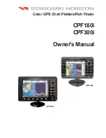
Page 1: ...CPF180i CPF300i Owner s Manual Color GPS Chart Plotters Fish Finder CPF180i CPF300i ...

Page 2: ...nterference with radio communications There is no guarantee that interference will not occur in a particular instance If this equipment does cause harmful interference to other equipment try to correct the problem by relocating the equipment Consult an authorized STANDARD HORIZON dealer or other qualified service technician if the problem cannot be corrected Operation is subject to the following c...

Page 3: ... use the index finger behind a corner to move the cloth across the surface in overlapping side to side strokes If the cloth is too wet a noticeable wet film will be left in its path and you will need to repeat the process If too dry the cloth won t glide easily and may damage the surface CAUTION The GPS Chart Plotter is designed for maritime use To avoid water intrusion ensure the C MAP BY JEPPESE...

Page 4: ...Page 6 CPF180i and CPF300i ...

Page 5: ...F RADIO 25 2 8 RADAR ANTENNA USA ONLY 26 2 9 PERSONAL COMPUTER CONNECTIONS 26 2 10 NMEA DATA PAGE 26 2 11 CPF300i VIDEO INPUT 27 2 11 0 Video Camera Input 27 2 11 1 VCR or DVD Input 27 2 12 DEMO MODE For DEALER USE 29 3 CONTROLS AND INDICATORS 31 3 0 CONTROLS AND CONNECTIONS 31 3 0 0 The CPF300i Soft Keys 32 3 1 GETTING STARTED 33 3 1 0 Power On Off and ShuttlePoint Knob operation 33 3 1 1 Cursor ...

Page 6: ...lite Imagery 61 6 0 7 Currents Prediction 62 6 0 8 Chart Language 63 6 0 9 Pictures or Diagrams 63 How to show the Pictures or Diagrams of a Object 64 6 0 10 Enhanced Port Info 65 7 CREATING MARKS 67 7 0 CREATING A NEW MARK USING THE CHART PAGE 67 7 1 EDITING A MARK 67 7 1 0 Deleting a Mark or Waypoint 68 7 1 1 Moving a Mark or Waypoint 68 7 2 MARKS WAYPOINTS LIST 69 7 3 CREATING A NEW MARK WITH T...

Page 7: ... PAGE 90 12 0 0 For CPF300i Focus Soft Key on Dual Chart Page 91 12 0 1 For CPF180i Change Focus on Dual Chart Page 91 12 0 2 Single Chart Page 92 12 0 3 Window Selections 92 12 0 4 Customizing the Data Windows 93 12 0 5 Additional Functions on Chart Page 94 12 0 6 Turning Off Information on Icon Points 94 12 0 7 Display Mode 95 12 0 8 Marine Settings 96 12 0 9 Depth Settings 96 12 0 10 Land Setti...

Page 8: ...120 15 0 4 Type of Data 120 16 MOBILARM 121 16 0 MOBILARM GPS CHART PLOTTER CONNECTION 121 16 1 SOFTWARE SETUP 122 16 2 MOBILARM STATUS 122 16 3 MOBILARM PTX 123 16 3 0 MOBILARM MOB alert is received 123 16 4 PLACING CURSOR ON THE PTX ICON 124 16 4 0 Delete PTX 125 16 4 1 Goto PTX 125 16 4 2 The MOBILARM Alarm Status List 126 17 FISH FINDER 129 17 0 ENABLE DISABLE 129 17 1 UNDERSTANDING THE FISH F...

Page 9: ...41 17 11 DISPLAY SETUP 142 17 11 0 Color Settings 142 17 11 1 Scrolling Speed 142 17 11 2 White Line 143 17 11 3 Fish Symbols 143 17 11 4 A Scope 143 17 12 TRANSDUCER SETUP 143 17 12 0 Keel Offset 143 17 12 1 Calibrate Water Speed 143 17 12 2 Calibrate Water Temp 144 17 12 3 Set Defaults 144 17 13 ALARMS 144 17 13 0 Shallow Water 144 17 13 1 Deep Water 144 17 13 2 Fish 144 17 13 3 Temperature Uppe...

Page 10: ... CPF300i 20 SPECIFICATIONS 151 20 0 CPF180i SPECIFICATIONS 151 20 1 CPF300i SPECIFICATIONS 152 20 2 FF MODULE SPECIFICATIONS 153 20 3 OPTIONAL WAAS GPS RECEIVER SPECIFICATIONS 153 21 APPENDIX TERMS 155 ANALYTICALINDEX 159 ...

Page 11: ...ngress The CPF180i and CPF300i are housed in rugged impact resistant cases with outstanding ergonomic design for effortless operation The CPF180i and CPF300i are IP56 water resistent The advanced features of the GPS Chart Plotter Fish Finder include CPF180i 5 320 x 232 sunlight readable display CPF300i 7 Hi Res 800x480 sunlight readable display Internal 50 Channel WAAS GPS CPF300i Video Input with...

Page 12: ...s Department at 741 827 7600 extension 6800 or e mail at yaesuparts vxstdusa com 1 1 0 CPF180i Packing List PART CODE ITEM S8002224A External bracket S8002225 Mounting knob with two washers S8002222 Dust cover T9101553 Power data cable S8002223 Flush mounting screws EM022U500 Flush mount template XUCMP0052 2 Amp fuse and holder EM022U107 Owner s Manual EM023U510 Quick Reference Guide 1 1 1 CPF300i...

Page 13: ...depthTransducer DST528A 1000W Bronze long stem depth tempTransducer ACCESSORIES PARTS NAME ITEM 1 3 OPTIONAL DOME OR OPEN ARRAY RADAR ANTENNAS The Radar antennas are supplied by SI TEX 631 996 2690 in the USA and Canada Refer to the table below for compatible models MODEL NUMBER DESCRIPTION MDS 1 2kW 24 Mile 12 4 diameter Radome antenna MDS 8 2kW 24 Mile 20 diameter Radome antenna MDS 9 4kW 36 Mil...

Page 14: ...Page 16 CPF180i and CPF300i ...

Page 15: ...ght INTERNAL GPS and press ENT 4 Move the ShuttlePoint knob to highlight OFF and press ENT INTERNAL GPS RESTART GPS NAVIGATION SPEED NAVIGATION FILTER High DIFF CORRECTION SOURCE WAAS EGNOS Off On Figure 2 GPS Setup menu 5 Press CLR to exit the GPS SETUP menu 6 Confirm the GPS Status page is showing satellite signal strength bars and receive a fix 2 0 MOUNTING THE GPS CHART PLOTTER The CPF180i and...

Page 16: ...ugh room to mount the GPS Chart Plotter and there are no obstructions 1 After a location is found peel the template label from the backing and apply the label to the mounting area 2 Drill a hole in one area of the cutout area that will allow the blade of a jig saw to be inserted Insert and cut out the area on the panel using the jig saw 3 Next drill the four holes required to insert the GPS Chart ...

Page 17: ...led on an extension or flush mounted Choose a location for the antenna that has a clear view of the sky and is not located within 3Feet of a Radar or other transmitting antennas Ensure there are no major obstructions or fixtures in the immediate proximity to the antenna The antenna relies on direct line of sight satellite reception If you are unsure of the chosen location temporarily mount the ant...

Page 18: ... received 1 Remove the threaded base from the antenna dome 2 To ease installation a flush mounting template for the antenna has been included 3 Apply the mounting template sticker to the area that was verified for GPS reception 4 Then drill out the 0 78 20mm and 0 13 3 2mm holes and remove the template 5 Insert the cable into the 0 78 20mm hole and route to the GPS Chart Plotter 6 Apply a small am...

Page 19: ... and white CPF300i If you have connected devices as shown in the following table and need to feed NMEA to other devices Autopilot RADAR you can parallel wires from the yellow brown or white wires to other devices NOTE RS232 not opto isolated electrical interface 2 4 0 CPF180i Connection Table Power Data Cable Pin Wire Color Description Connection Example Additional Comments 1 Black Battery Ground ...

Page 20: ...ire and the Autopilot is not reading the sentences change the connections to Port1 Brown wire and change the sentences to APA APB BOD GGA GLL RMC and XTE NOTE RS232 not opto isolated electrical interface 2 4 1 CPF180i Connections 2 4 1 0 DC Power Connection Battery 10 35Vdc Red 2A Fuse Black Switch Optional WAAS GPS ntenna a CPF180i PWR ACC 1 Cable Transducer 2 4 1 1 Connection of the AIS Receiver...

Page 21: ...ect AIS 38400 and press ENT or move the ShuttlePoint knob to the right NOTE IfanAISreceiverisnotconnected Port1InputcanbeconnectedtomostDSCVHF sforpositionpolling NOTE The Input and Output baud rate for each port is set using the Advanced Setup In Out Connections menu For example if Port1 is set for AIS 38400 the Input and Output both operate at 38400 baud 2 4 2 CPF300i Connection Table 12VDC Powe...

Page 22: ...s set using the Advanced Setup In Out Connections menu For example if Port1 is set for AIS 38400 the Input and Output both operate at 38400 baud 2 4 3 2 AIS Setup The CPF300i has to be set up to be able to receive NMEA information from the AIS receiver The GPS Chart Plotter reads the AIS NMEA message VMD type 1 2 3 and 5 for AIS Class A and type 18 19 24 for AIS Class B Select the used serial port...

Page 23: ...ncements in DSC have made it possible to show the coordinates of a vessel that has transmitted a DSC Distress Call or even Polled the location of another vessel and show the position of that vessel on the display of STANDARD HORIZON VHFs STANDARD HORIZON has taken this feature one step further If a CPF180i or CPF300i is connected to a DSC capable VHF the vessel in Distress or the polled position o...

Page 24: ...the User Points on a different Port using the following procedure 1 Press MENU move the ShuttlePoint knob to highlight SETUP MENU and press ENT 2 Move the ShuttlePoint knob to highlight ADVANCED SETUP and press ENT or move the ShuttlePoint knob to the right 3 Move the ShuttlePoint knob to highlight IN OUT CONNECTIONS and press ENT or move the ShuttlePoint knob to the right 4 Move the ShuttlePoint ...

Page 25: ...sible to see images on the CPF300i display from an external video signal source if connected to the CPF300i It allows the picture in picture functionality so a Video Input image can be shown on a window and placed over the Chart Navigation Highway Celestial and NMEA pages image at full screen NOTE If theVideoInputsignalsisnotdetected E g thevideocameraisnotconnectedtotheVideoInput connector the VI...

Page 26: ...put Full View if connected and the selected page See next section for details of setting up the switching times If the user agrees to proceed the image from the Video Input and the CPF300i page will be shown intermittently The intermittence time is selected by Switching Timeout item b SWITCHING TIMEOUT the possible choices are 5 10 30 sec 1 5 10 min Allows selecting the timing to change from Video...

Page 27: ... up screen GPS Status page Chart Compass tape page Chart Fish Finder page Fish Finder Full page Radar page Navigation page Highway Page Celestial page NMEA Display page NOTE This mode is used by dealers to promote the features of the CPF180i or CPF300i when on a retail shelf The Demo mode can be selected from the Simulation Menu following the procedure 1 Press MENU move the ShuttlePoint knob to hi...

Page 28: ...Page 30 CPF180i and CPF300i ...

Page 29: ...of a smaller area by changing the chart scale and zooming in on your display Press ZOOM OUT to change the scale and show a wider otherwise less detailed view Pressing and holding ZOOM IN ZOOM OUT allows for quick zoom that is the fast change of the chart scale where only the land areas are drawn When ZOOM IN ZOOM OUT is released all chart details are shown NOTE The GPS Chart Plotter contains a Wor...

Page 30: ...e rescue or a person that may have fallen aboard To stop navigating press GOTO select STOP and press ENT The FIND key A dedicated key that allows searching the optional C MAP BY JEPPESEN NT MAX C CARD for Port Services Ports Tide Stations Wrecks Obstructions Points Of Interest Lakes Information Lakes By Name User Points GPS Coordinates or Information on any point on the chart 3 0 0 The CPF300i Sof...

Page 31: ...CPF180 2 When the power is first turned on two pages the start up page and the Caution pages are briefly shown before the GPS Status page WARNING Figure 3 1 0a Example of Caution pages NOTE The Caution page on the left is shown only if the data C CARD is over one year old 3 When the GPS Chart Plotter is first turned on it will take some time for the GPS to acquire a fix of your position Look close...

Page 32: ...ome Mode Cursor Mode When the cursor is shown on the Chart Page the chart plotter is in Cursor Mode In Cursor Mode the position of the vessel will not stay in the center of the page and will move right off the edge of the screen as your boat moves Cursor Mode allows you to pan around and look at areas on the chart In this mode you can also create Marks Routes measure distance and bearings from you...

Page 33: ...the menu disappears or an easier method is to press the ShuttlePoint knob to the left a few times 7 Move the cursor on the Chart Page and see if the speed is to your liking 3 1 3 Changing the Ship Icons The cursor may be changed to any of the following The default setting is Icon 6 Icon 1 Icon 2 Icon 3 Icon 4 Icon 5 Icon 6 Icon 7 Figure 3 1 3 Ship icons 1 Press MENU move the ShuttlePoint knob to h...

Page 34: ...3 Move the ShuttlePoint knob to highlight COURSE UP NORTH UP and press ENT or move the ShuttlePoint knob to the right 4 Another popup window will be shown with NORTH UP and COURSE UP move the ShuttlePoint knob to the desired selection and press ENT or move the ShuttlePoint knob to the right 5 Press CLR or move the ShuttlePoint knob to the left to exit the menu and show the Chart page NOTE When the...

Page 35: ...ess ENT or move the ShuttlePoint knob to the right 3 Move the ShuttlePoint knob to highlight TIME SETUP and press ENT or move the ShuttlePoint knob to the right 4 Move the ShuttlePoint knob to highlight TIME ZONE and press ENT or move the ShuttlePoint knob to the right 5 Look at the table and find the time zone for your area Move the ShuttlePoint knob up or down to select the desired zone and pres...

Page 36: ... to the right 4 Move the ShuttlePoint knob to highlight COORDINATE SYSTEM and press ENT or move the ShuttlePoint knob to the right 5 Move the ShuttlePoint knob to highlight the desired coordinate type and press ENT or move the ShuttlePoint knob to the right 6 Press CLR or move the ShuttlePoint knob to the left until the Chart page is shown NOTE If the TD is selected you should set the Chain Pair A...

Page 37: ...Menu descriptions Soft Key labels and on Info Functions to ease operation See also Par 6 0 7 Set the language to be displayed on menus data pages warning alarm messages full quick info list of objects found by find nearest function and on charts such as place s names and buoy s names and so on The selection now includes the capability to display languages in non Latin characters UNICODE format To ...

Page 38: ... of the Soft Keys is pressed popup windows above each Soft Key are shown with the key description Press the Soft Key with the desired page description and the GPS Chart Plotter will change to that page WAAS 3D WAAS 3D WAAS 3D CHART CELESTIAL HIGHWAY NAVIGATION GPS STATUS NMEA DISPLAY Chart 200KHz Display example with RADAR connected WAAS 3D Figure 3 6 Screen display pages 3 7 CUSTOMIZING THE SOFT ...

Page 39: ...SENTATION Allows the Nav Aids presentation to be drawn using NOAA symbology when US default isselectedorInternationalsymbolswhen Internationalisselected Whenselectedthese functions affect how the icons for Lights Signals Buoys and Beacons are displayed DISPLAY COLOR Changes the background colors of the chart page to enhance the visibility of the screen depending on the surrounding light conditions...

Page 40: ...anging the language for menus and data screens AUTO INFO When the cursor is moved over a buoy Mark or other item a popup window will show information of the item This menu item allows the window to be turned Off On Points default or On All Auto Info OFF Auto Info ON POINTS Auto Info ON ALL CURSOR WINDOW By default when the cursor is moved a window is shown with the Lat Lon Distance and Bearing fro...

Page 41: ...ormation 2 Cartography Information Software System Information 1 3 Storage Capacity XXXXXX YY YY INTCHART 1 WW M012 03 MARINE FRESHWATER WWBK M NA M632 00 LOS ANGELES and SAN PEDRO BAYS 1 2 3 Designed for 1 Figure 3 9 Example of About page 1 Press MENU move the ShuttlePoint knob to highlight SETUP MENU and press ENT 2 Move the ShuttlePoint knob to highlight About and press ENT or move the ShuttleP...

Page 42: ...Page 44 CPF180i and CPF300i ...

Page 43: ...ight PORT SERVICES and press ENT or move the ShuttlePoint knob to the right 3 A popup window will be shown with a list of different Port Services The table below shows a list of the available Port Services Figure 4 0 0 Port Services Table 4 Move the ShuttlePoint knob to highlight the desired type of service and press ENT 5 Another popup window will appear displaying the distance and position of th...

Page 44: ...he details of the selected Port 6 Press CLR to show the actual position of the Port on the Chart Page 7 Press CLR again at any time to return your cursor to your vessel s position WAAS 3D Figure 4 0 1 Find a Port 4 0 2 Tide Stations This feature is used to locate the 10 nearest Tide Stations to the position of your vessel Once a Tide Station is selected the Tide Graph can be used to determine Tide...

Page 45: ...the location of the cross haircursor 2 intheTideGraph 1 MovingtheShuttlePointknobtotheleftorrightchanges the time and moving the ShuttlePoint knob up or down selects the Tide height and Tide draught on the Tide Graph NOTE The Local Offset matchs the Time Offset entered in the Time Setup menu see Par 3 2 4 0 3 Wrecks This feature is used to locate the 10 nearest Wrecks to the position of your vesse...

Page 46: ...structions to the position of your vessel An Obstruction is represented with an icon on the chart see the following table snag stump wellhead diffuser crib fish haven foul ground ice boom ground tackle foul area ICON DESCRIPTION F o u l Obstn 46 Obstn Wk Mast 1 2 Figure 4 0 4 Obstruction icons Table 1 Press FIND 2 Move the ShuttlePoint knob to highlight OBSTRUCTIONS and press ENT or move the Shutt...

Page 47: ...nob to the right 3 A popup window will be shown with a list of Outdoor Recreational Area objects 4 Move the ShuttlePoint knob to highlight the desired object and press ENT 5 Another popup window will appear displaying the distance and position of the Lakes closest to your location 6 Using the ShuttlePoint knob highlight the desired Lake and press ENT This will show information on the Lake 7 Press ...

Page 48: ...uick Info available services If you press ENT all available information about the cartographic point under the cursor will be shown See the next paragraph 4 0 5 1 Full Info On Lakes The following is an example of Full Info on Lakes Figure 4 0 5 1 Example of Full Info page To see the Fishing object press MENU when the Fishing object is highlighted On the screen appears ...

Page 49: ...l appear displaying the distance and position of the Lake 5 Press ENT to show the actual position of the Lake on the Chart Page 6 Press CLR twice to return your cursor to your vessel s position 4 0 7 Points Of Interest This feature is used to locate Points Of Interest nearest the position of your vessel 1 Press FIND 2 Move the ShuttlePoint knob to highlight POINTS OF INTEREST and press ENT or move...

Page 50: ...ve the ShuttlePoint knob to highlight USER POINTS and press ENT or move the ShuttlePoint knob to the right 3 The Select Name popup window will appear This window will allow you to enter in the name of the User Point you wish to locate 4 Move the ShuttlePoint knob up down to change each number or letter and left right to move to the next or previous position in the name of the Mark 5 Once the name ...

Page 51: ...n your cursor to your vessel s position WAAS 3D INFORMATION Figure 4 0 9 Find GPS Coordinates 4 0 10 Information This feature allows you to obtain information on any position on the Chart page 1 Press FIND 2 Move the ShuttlePoint knob to highlight INFORMATION and press ENT or move the ShuttlePoint knob to the right 3 A page will be shown with objects information The upper side of the page contains...

Page 52: ...Page 54 CPF180i and CPF300i ...

Page 53: ...igure 5 0a Inserting C CARD details NOTE The small connector below the C CARD is only used by Standard Horizon repair technicians Key points are Data Features ISO Certification electronic chart production process with quality certification Extra Large Coverage all the C Map electronic chart detail and a huge coverage without having to change cartridge Official data source data based on use of offi...

Page 54: ...e plotter to show language of your choice in using proper character set for Asian and other countries True Type Font improves text on chart for optimal reading Presentation Features Clear View advanced legibility techniques providing more chart data on the screen Clear Info sophisticated Human Dictionary to translate Nav Aid abbreviations found on paper charts Flexi Zoom increased Under and Over Z...

Page 55: ...ctions menu is described in the following 6 0 0 Zoom Type Zoom Type refers to the chart scale selection It has two options Standard default or Flexi Zoom When Zoom Type is set to Flexi Zoom a short ZOOM IN ZOOM OUT push causes a change of chart level while a long ZOOMIN ZOOMOUT push press and hold causes an expansion or compression of the chart image without a chart level change CHART US NOS GRAPH...

Page 56: ...ntil the menu disappears or an easier method is to move the ShuttlePoint knob to the left a few times 6 0 1 Icon Size On MAX charts it is possible to set the size of all icons drawn on the charts selecting between Standard default and Large size ICONS SIZE standard ICONS SIZE large Figure 6 0 1 Icons Size To activate this function follow the procedure 1 Press MENU move the ShuttlePoint knob to hig...

Page 57: ...al mode during navigation Perspective view of the chart is a type of bird s eye view of a chart and give you a more realistic perspective of the chart As the upper side of the chart is more compressed than the lower side a wider chart area is visible so it allows showing more chart information immediately ahead and around the cursor Perspective View ON Perspective View OFF Figure 6 0 3 Perspective...

Page 58: ...arning or alarm condition is identified by the red color to indicate possible risk To activate this function follow the procedure 1 Press MENU move the ShuttlePoint knob to highlight SETUP MENU and press ENT 2 Move the ShuttlePoint knob to highlight MAX FUNCTIONS and press ENT or move the ShuttlePoint knob to the right 3 Move the ShuttlePoint knob to highlight SAFETY STATUS BAR and press ENT or mo...

Page 59: ...ties Pingos and Production installations Red when Guardian Technology detects cautionary or restricted area Safety Status Bar O ZOOM DANGERS CAUTIONS BEST MAP DATA OFF DECLUT Figure 6 0 5 Safety Status Bar 6 0 6 Satellite Imagery This function allows to overlay the Satellite image for background chart When it is set On the Palette is set to Normal to display the proper colors NOTE The satellite im...

Page 60: ... to 0 1 kn 0 2 to 1 0 kn 1 1 to 2 0 kn 2 1 to 3 0 kn 3 1 to 9 9 kn Yellow Yellow Orange Orange Red Figure 6 0 7a Tidal stream arrows table When the GPS Chart Plotter receives a valid position fix the Tide icons are shown on the charts on the basis of the current date and time the screen displays and changes arrows as date time changes It is possible to see the variation of the Tidal arrows on the ...

Page 61: ...charts Mode Defines how objects are translated Selections are Off Enables the language chosen in the Language menu above If the selected language is not present on the objects information English is used English Always uses English Local Uses the Local language present on C MAP BY JEPPESEN C CARD If no Local language is available English is used 4 After the selection is made press CLR repeatedly o...

Page 62: ... of Quick Info on camera icon on CPF300i On the CPF300i press IMAGE or on the CPF180i press ENT for 1 second to display the image on the screen Figure 6 0 9c Example of displayed image on CPF300i Otherwise on the CPF300i press EXPAND or on the CPF180i press ENT to open the Full Info on the object Note that on the Full Info there is the small camera icon on a corner of the square containing the obj...

Page 63: ... 0 10 Enhanced Port Info Optional C MAP BY JEPPESEN MAX C Cards include additional Port Services that were not present before Additional attributes of Port Areas and Port Marinas have been included as Location Country Region State Harbour master telephone number etc see the following figure PORT icon 1 1 WAAS 3D Figure 6 0 10 Example of enhanced Port Info on CPF300i ...

Page 64: ...Page 66 CPF180i and CPF300i ...

Page 65: ...ed under the location of the Cursor and a popup window is shown with the exact Lat Lon of the Mark 3 If the position is incorrect on the CPF180i press ENT select EDIT using the ShuttlePoint knob and press ENT On the CPF300i press EDIT that will allow you to change the position Mark name and icon type Refer to Par 7 1 for details Vessel location Mark placed under Cursor Lat Lon of Mark DST BRG from...

Page 66: ...ht to select the Lat Lon and press ENT 9 Move the ShuttlePoint knob up or down to select the first character 10 Move the ShuttlePoint knob to the right to select the next character 11 Repeat steps 9 and 10 until the desired position is shown Press ENT and CLR to store the Mark 7 1 0 Deleting a Mark or Waypoint 1 Move the ShuttlePoint knob over the Mark or Waypoint to delete 2 On the CPF180i press ...

Page 67: ...ints Selections are a A Z ASCENDING Sorts the name of the Mark or Waypoint in ascending order b Z A DESCENDING Sorts the name of the Mark or Waypoint in descending order NEW MARK Allows you to create and edit a new Mark Useful when entering many Marks from a list MODE This selection controls how the Marks or Waypoints are shown on the Chart page Selections are a SHOW icon and name are shown b ICON...

Page 68: ...e ShuttlePoint knob to highlight the desired Icon and press ENT 7 Move the ShuttlePoint knob to the right to select the Mark name Press ENT and the first digit in the name will be highlighted 8 Move the ShuttlePoint knob up or down to select the first character 9 Move the ShuttlePoint knob to the right to select the next character 10 Repeat steps 8 and 9 until the Mark name is shown Press ENT 11 M...

Page 69: ...R 1 Move the ShuttlePoint knob to the exact position you want to navigate to 2 Press GOTO and a GOTO popup window will be shown Figure 7 4 GOTO menu 1 3 Move the ShuttlePoint knob to highlight CURSOR and press ENT Figure 7 4a GOTO menu 2 4 The GPS Chart Plotter is now navigating from your current position to the location selected at step 1 A bearing line between the vessels location and the destin...

Page 70: ...on the Chart page move the cursor over the designed Waypoint and press GOTO For more information about Routes refer to Section 9 GOTO MARK 1 Move the ShuttlePoint knob to an open position no buoy warning etc under the cursor on the Chart page 2 Press GOTO to show the GOTO popup window 3 Move the ShuttlePoint knob to highlight MARK and press ENT to show the MARKS WAYPOINTS List 4 Move the ShuttlePo...

Page 71: ... MOB Mark will be on the Chart page and all navigation is referring back to this point 3 On the CPF300i If the cursor is moved over the MOB Icon the popup windows over Soft KeyswillbeshownallowingquickaccesstotheHighwayorNavigationpage ortoRoute Check 4 To stop navigating to the MOB point press GOTO select STOP and press ENT Figure 8 0 MOB point 8 1 DELETING A MOB POINT 1 Move the ShuttlePoint kno...

Page 72: ...Page 74 CPF180i and CPF300i ...

Page 73: ...dicular of the NAVIGATION LINE the Destination is moved to then next Waypoint in the Route WPT001 Destination Figure 9 Example to show how the plotter switches from one Waypoint to another 9 0 CREATING A ROUTE USING WAYPOINTS 1 On the Chart page move the ShuttlePoint knob to the Lat Lon of the starting Waypoint in the Route 2 Press ROUTE you will notice the Starting Waypoint will be placed under t...

Page 74: ...ob up down to change the characters and left right to select a different character in the Routes Name EDIT ROUTE Figure 9 1 Edit Route Route Report 6 When finished press ENT to save 7 Press CLR to show the Chart page 9 2 CREATING AN OLYMPIC ROUTE This feature allows the starting point in a Route to be saved as the final destination point 1 On the Chart page move the ShuttlePoint knob to the Lat Lo...

Page 75: ...s ENT 2 Move the ShuttlePoint knob to highlight ROUTE and press ENT 3 Move the ShuttlePoint knob to highlight SELECT and press ENT or move the ShuttlePoint knob to the right 4 Move the ShuttlePoint knob to an open Route number example Route 2 5 Press ENT or move the ShuttlePoint knob to the right 6 Press CLR or move the ShuttlePoint knob to the left until the Chart page is shown 7 To create the ne...

Page 76: ...Shuttle Point knob to the right A popup window will be shown 9 Move the ShuttlePoint knob up down to change the characters and left right to select a different character in the Routes Name 10 When finished press ENT to save 11 Press CLR to show the Chart page is shown 9 5 INSERTING A WAYPOINT INTO A ROUTE On the CPF180i place the cursor on the navigation line between two Waypoints and press ROUTE ...

Page 77: ...he Chart page 2 Press GOTO to show the GOTO popup window 3 Move the ShuttlePoint knob to highlight ROUTE and press ENT 4 The SELECT ROUTE popup window will be shown Figure 9 6 0 GOTO ROUTE procedure 1 5 Move the ShuttlePoint knob to the highlight the desired Route and press ENT 6 OntheChartpageacirclewithaflagisshownonthefirstlegoftheRouteandanavigation line is shown indicating the GPS Chart Plott...

Page 78: ...hart page REVERSE Reverses the Route when chosen Starting point is at the end of the Route COLOR Allows changing the color of the navigation lines between each leg in the Route EDIT The Edit Route Route Report menu is useful to show details of the Waypoints contained within the Route This menu also allows you to enter in your average speed and fuel consumption and calculate the approximate fuel us...

Page 79: ...urn the Automatic Route Check on after you have created a new Route or if you inserted a new Waypoint deleted moved or edited any Waypoint in a saved Route to confirm the Route can be safely navigated ROUTE WIDTH This selection allows you to select the width from the left and right of the Route leg where theGPSChartPlotterwillchecktoconfirmnavigationthreats Seethepicturebelow The default for this ...

Page 80: ...onality is called Route Check it can also be activated when the navigation is set to a single point like DSC MOB Mark In the case of checking a single point towards which the navigationisstarted thelegforwhichtheRouteCheckisexecutedisdefinedbythecurrentposition the leg s starting point and the destination point the leg s ending point ...

Page 81: ...ve the ShuttlePoint knob to highlight USER POINTS and press ENT 2 Move the ShuttlePoint knob to highlight TRACK and press ENT 3 Move the ShuttlePoint knob to highlight STEP UNIT and press ENT or move the ShuttlePoint knob to the right 4 Move the ShuttlePoint knob to highlight Dist or Time and press ENT or move the ShuttlePoint knob to the right Figure 10 Distance Units and Time Units 5 Move the Sh...

Page 82: ... 1 Deleting a Track To delete a Track 1 Press MENU move the ShuttlePoint knob to highlight USER POINTS and press ENT 2 Move the ShuttlePoint knob to highlight TRACK and press ENT 3 Move the ShuttlePoint knob to highlight DELETE and press ENT or move the ShuttlePoint knob to the right 4 A warning popup window will be shown to confirm if you want to reset the Track Move the ShuttlePoint knob to high...

Page 83: ...tlePoint knob to select the desired units of measure and press ENT or move the ShuttlePoint knob to the right 4 Press CLR or move the ShuttlePoint knob to the right until the selected page Chart Navigation Highway or NMEA Data Page is shown 10 1 1 Setup Reset When Trip Log is selected in one of the data windows and you want to reset the log 1 Press and hold MENU until a field is highlighted it wil...

Page 84: ...Page 86 CPF180i and CPF300i ...

Page 85: ...a contained in the file Mark file Waypoint file File name Number of Selected file Information on stored User Points on Internal Memory Time of file creation Date of file creation 4 5 2 1 3 6 Figure 11 0 User C CARD Menu 11 0 0 Formatting the optional User C CARD 1 Press MENU movetheShuttlePointknobtohighlightUSERPOINTSandpress ENT 2 Move the ShuttlePoint knob to highlight USER C CARD and press ENT...

Page 86: ...the ShuttlePoint knob and press ENT 4 Move the ShuttlePoint knob to the left to highlight LOAD and press ENT 5 A popup information window will appear when loading is complete 6 Press ENT to confirm 11 0 3 Deleting a file from the optional User C CARD You may want to delete a saved file on the User C CARD 1 Press MENU move the ShuttlePoint knob to highlight USER POINTS and press ENT 2 Move the Shut...

Page 87: ...y example with RADAR connected WAAS 3D WAAS 3D WAAS 3D Figure 12 Example of screen display pages The pages can be selected in the following way Selection by MENU This function is available on the CPF180i and CPF300i 1 Press MENU The following menu is shown on the screen Figure 12a Main Menu on CPF180i Figure 12b Main Menu on CPF300i 2 Move the ShuttlePoint knob to highlight the desired page and pr...

Page 88: ...Chart Plotter is provided with a Worldwide background showing C MAP BY JEPPESEN NT MAX detail up to 2 0 NM For more detail optional C MAP BY JEPPESEN NT MAX C CARDs are available refer to Par 5 0 It is possible to set the chart as a single or two charts side by side 1 Press MENU move the ShuttlePoint knob to highlight CHART and press ENT Two Chart page types are available Single and Dual 2 Move th...

Page 89: ...ppears where the active focus window label is highlighted Figure 12 0 0a Example of Dual Chart page with FOCUS window shown 3 Move the ShuttlePoint knob up and down to highlight the desired item and press ENT The red boarder is moved to the focused window For CPF180i 12 0 1 Change Focus on Dual Chart Page WhenDualChartisselected youwillnoticeoneofthechartwindowswillhavearedboarder around it This r...

Page 90: ...the Two Line Small window The CPF180i and CPF300i windows may be changed by the procedure below FULL CHART None GENERAL 1 LINE SMALL 1 LINE LARGE 2 LINES SMALL HIGHWAY COMPASS WAAS WAAS 3D Figure 12 0 3 Data window layout 1 To change press MENU move the ShuttlePoint knob to highlight SETUP MENU and press ENT 2 Move the ShuttlePoint knob to highlight GENERAL SETUP and press ENT or move the ShuttleP...

Page 91: ...e TIME Current Time VMG Velocity Made Good ETA Estimated Time of Arrival TRACKING Tracking SCALE Chart Scale GPS Status Shows GPS Fix Status WAAS 3D 2D NOTE1 When the GENERAL window is selected and the GPS chart plotter is in Home Mode the BRG will show unless the GPS chart plotter is navigating to a point When in Cursor Mode the BRG shows the Bearing from the ship s position to the cursor locatio...

Page 92: ...you to select to see information On Points On All items or to turn this function off The default setting is On Points 1 Press MENU move the ShuttlePoint knob to highlight SETUP MENU and press ENT 2 Move the ShuttlePoint knob to highlight GENERAL SETUP and press ENT or move the ShuttlePoint knob to the right 3 Move the ShuttlePoint knob to highlight AUTO INFO and press ENT or move the ShuttlePoint ...

Page 93: ... knob to the right until the Chart page is shown CHART Figure 12 0 7 Display Mode settings The table below shows the selections for each mode Setting Full Medium Low Radar Tides Custom Default values Place Names On On On On On On Name Tags On Off Off Off Off Off Nav Aids Light Sectors On No Sectors No Sectors No Sectors Off On Attention Areas On On Off Off Off Off Tides Currents On Off Off Off On ...

Page 94: ...lotter is not in Simulation mode the icon on the chart is generic one The color of the arrow denotes the strength of the current as follows 0 to 0 1 kn 0 2 to 1 0 kn 1 1 to 2 0 kn 2 1 to 3 0 kn 3 1 to 9 9 kn Yellow Yellow Orange Orange Red When the GPS Chart Plotter receives a valid position fix the Tide icons are shown on the charts on the basis of the current date and time the screen displays an...

Page 95: ... 11 Chart Settings Settings that control how the chart features will be shown on the Chart page of the GPS Chart Plotter Lat Lon Grid Turns the Latitude and Longitude grid lines on or off on the chart page See the figure below Lat Lon Grid ON Lat Lon Grid OFF Chart Boundaries Turns the Chart Boundaries On Off or Auto The Chart Boundaries are the ticked boxes sourround the coastline Each box indica...

Page 96: ...rest of the chart using charts from above and below the current scale When this function is turned on you will notice the display may redraw 2 to 3 times to show all the details NOTE When an empty level is entered the message No cartographic coverage is shown on a window in a corner of the chart display The warning message is always displayed as long as the current zoom has no data coverage 12 0 1...

Page 97: ...estination followingacompassa heading or navigating to a Mark or a Route The default page is shown with a Compass Rose however this can be customized to show a Compass Tape 1 To change to show the Compass Tape select the Chart page press MENU Move the ShuttlePoint knob to highlight SETUP MENU and press ENT 2 Move the ShuttlePoint knob to highlight GENERAL SETUP and press ENT or move the ShuttlePoi...

Page 98: ...ighway scale WAAS 3D Course over ground 4 2 1 3 Bearing Speed Over Ground Highway Display Highway Scale 5 1 3 2 5 4 Figure 12 3 Highway page 12 4 CELESTIAL PAGE The Celestial page contains Tide information critical for safe navigation This page is also useful for boaters that are concerned about the height of the water under a bridge or by fisherman that wish to know the tide and moon phase of a s...

Page 99: ...nder your keel at a time of day where the water is the highest High Water Let s say the High Water window shows 5Feet and the Low Water window shows 1Feet this means the water under your vessel over a 24 hour period of time could fall 4Feet High Water Low Water With your vessel in 15Feet of water and with a maximum water change of 4Feet during the day the worst case situation there will be 11Feet ...

Page 100: ...ART GPS NAVIGATION SPEED NAVIGATION FILTER High DIFF CORRECTION SOURCE WAAS EGNOS Off On Figure 12 5 1 Setup menu From this page it is possible to activate the GPS Setup menu following this procedure 1 Press MENU move the ShuttlePoint knob to enter GPS STATUS page and press ENT 2 Press and hold ENT The GPS SETUP menu appears on the screen See the following table Internal GPS Enables On or disables...

Page 101: ...HDM HDT RMC VHW VTG DPT DBT MTW VWR VWT TLL WPL RTE CHANGING the NMEA PAGE Windows 1 On the CPF180i press MENU Move the ShuttlePoint knob to highlight NMEA DISPLAY and press ENT Figure 12 6a NMEA Display menu on CPF300i 2 The CPF300i can use step 1 and from the factory the right most Soft Key is programmed for direct access Press this key two times to show the NMEA Display page Move the ShuttlePoi...

Page 102: ... wire The display should look similar to the following picture Figure 12 7a NMEA Data page 4 Press ENT to freese the data on the display so it is easy to read and understand 5 Press ENT again to receive data again 6 View data from a device connected to another data port press the ZOOM IN 12 8 NMEA TREND PAGES The CPF180i and CPF300i have the following NMEA Trend pages Trends will be shown for Dept...

Page 103: ...his new system allow mariners to instantly send a distress call with GPS position when connected to the transceiver to the US Coast Guard and other vessels within range of the transmission DSC will also allow mariners to initiate POSITION Request POSITION Report calls to or from another vessel equipped with a DSC transceiver Compatible VHF Marine Radios with Digital Selective Calling are able to b...

Page 104: ...een Figure12 9 0 Interfacing to VHF Radio for CPF180i Interfacing to VHF Radio For CPF300i VHF Wires Blue Gray Green Description Brown wire GPS chartplotter outputs data to VHF Gray wire VHF outputs DSC data to GPS chartplotter Green is data common ground CPF300i Brown Blue Black Figure12 9 0a Interfacing to VHF Radio for CPF300i 12 9 1 Distress Call STANDARD HORIZON GPS chart plotters are able to...

Page 105: ... vessel when connected DSC VHF radio and when a Position Request or Report call is received STANDARD HORIZON GPS also log DSC Distress calls to review at a later date 1 Press MENU and move the ShuttlePoint knob to highlight USER POINTS and press ENT 2 Move the ShuttlePoint knob to highlight DSC Log and press ENT 3 Move the ShuttlePoint knob to the right to select POSITION REQUEST and press ENT 03 ...

Page 106: ...Page 108 CPF180i and CPF300i ...

Page 107: ... the following NMEA 0183 NMEA devices set to 4800 Baud default setting C Com C Weather refer to Section 15 Radar SI TEX optional Radar refer to Radar Owner s Manual AIS38400 AIS Receiver refer to Section 14 MOBILARM Mobil arm receiver refer to Section 16 Disabled allow the port to be disabled NOTE When a Port is configured both the Input and Output have the same setting Port1 is set to Radar both ...

Page 108: ...art is redrawn and Static Navigation See the following table Coordinate System Selections are a TD Time Difference based on Loran see the following Par 13 1 0 b UTM Universal Transverse Mercator Grid c ddd mm mmm Degrees Minutes and Thousands of Minutes d ddd mm mm Degrees Minutes and Hundredths of Minutes e ddd mm ss Degrees Minutes and Seconds default Chart Datum Allows selection of Chart Datums...

Page 109: ...enter delay values to fine adjust the position calculated Alter Alternate Solution TD Coordinate System Parameter selected by the user that is applied in the conversion of geographical coordinates Lat Lon to TD values To be used if the position displayed is roughly not correct 13 2 COMPASS The GPS Chart Plotter computes compass direction from the constellation of GPS Satellites For the GPS Chart P...

Page 110: ...warning appears when the Grounding Alarm is enabled NOTES TheGroundingAlarmfunctionisavailableonlyifaNT MAXC CARDisinserted Italsoaffectsthe screen redraw speed so we suggest to disable it when not used When any of the objects checked are found for the first time the GPS Chart Plotter shows a pop up window to alert the user of the possible danger The name of each new dangerous object found is repo...

Page 111: ...int knob to highlight ROUTE and press ENT which will show a popup window with the Route s that are stored in the GPS Chart Plotter s memory 7 Highlight the desired Route and press ENT 8 Move the ShuttlePoint knob to highlight SPEED and press ENT 9 Enter in the speed you want to vessel to travel at in simulation mode by moving the ShuttlePoint knob left or right to select a number and up or down to...

Page 112: ...Page 114 CPF180i and CPF300i ...

Page 113: ... CPA Limit This is the distance from your vessel that a target may reach before a target is deemed a threat CPA Alarm Occurs if CPA is less or equal to CPA Limit This test is done for active targets only TCPA Time to closest Point of Approach is the time remaining until the CPA will occur TCPA Limit This is the time remaining before the CPA is reached TCPA Alarm Occurs if TCPA is less or equal to ...

Page 114: ... menu appears on the screen The available functions are described in the following table Display Turns the display of AIS Targets overlay on the cartography On or Off The default setting is On Activation Range Defines the range from the fix within which the AIS Target becomes active The values allowed are from 0 1 to 20 Nm The default setting is 5 Nm CPA Alarm Turns On or Off the alarm The default...

Page 115: ...w the procedure 1 Press MENU movetheShuttlePointknobtohighlightUSERPOINTSandpress ENT 2 Move the ShuttlePoint knob to highlight AIS LIST and press ENT Figure 14 4 AIS List page 3 Move the ShuttlePoint knob up or down to select the Target and scroll the page up or down Press ENTER exitsthepageandshowstheTargetshipontheChartpagealong with the current position of the GPS Chart Plotter 14 5 AIS TARGET...

Page 116: ...ark blue Pilot Vessel light gray SAR black Tug pale green Port tenders brown Vessels with antipollution facilities or equipment light blu Low enforcement vessels light red Medical transport dark green Vessels according to Resolution N 18 Mob 83 cyan HSC red Passenger ship magenta Cargo ship dark gray o Figure 14 5 Color AIS Targets ...

Page 117: ...MIDITY 30 VISIBILITY 20 WEATHER TYPE Sun WEATHER TYPE Rain WEATHER TYPE Fog WEATHER TYPE Snow WEATHER TYPE Clouds WEATHER TYPE Partly Cloudy WEATHER TYPE Thunderstorm Data Type Display Figure 15 Weather data package 15 0 C WEATHER SERVICE MENU To select the menu 1 Press MENU move the ShuttlePoint knob to highlight SETUP MENUand press ENT 2 Move the ShuttlePoint knob to highlight C WEATHER SERVICE ...

Page 118: ...ARD 15 0 2 Weather Forecast Allows selecting the Layer of specific weather data to be displayed on the screen and to change date and time of the forecast preview The following functions are available Panning default usage of the cursor key is the normal panning function Zoom in out zoom in out functions are allowed as usual by using ZOOM IN ZOOM OUT Set of date and time DATE or GOTO for CPF180i to...

Page 119: ... the vessels position is shown on the Standard Horizon GPS Chart Plotter 16 0 MOBILARM GPS CHART PLOTTER CONNECTION Connect the MOBILARM system to one of the Ports on the Standard Horizon GPS Chart Plotter Refer to Par 2 4 0 Connection Table for CPF180i Par 2 4 2 Connection Table for CPF300i and MOBILARM Owner s Manuals for connections Connection Example Blue Brown Black Green Red PWR ACC 1 Cable ...

Page 120: ...nt knob to highlight IN OUT CONNECTIONS and press ENT or move the ShuttlePoint knob to the right 5 Move the ShuttlePoint knob to highlight any input port and press ENT or move the ShuttlePoint knob to the right 6 Move the ShuttlePoint knob up down to select MOBILARM and press ENT or move the ShuttlePoint knob to the right Selecting MOBILARM format activates the function 7 Press CLR or move the Shu...

Page 121: ...LES and SAN PEDRO BAYS XXXXXX YY YY Not detected MOBILARM status Information 1 10000 20 Figure 16 2 Example of About page with MOBILARM information on CPF300i 16 3 MOBILARM PTX A PTX is the Personal Transponder device that is worn by the crew If a crew member falls in the water the MOBILARM sends a signal to the GPS Chart Plotter which creates and displays a PTX icon on the Chart page 16 3 0 MOBIL...

Page 122: ... PTX is received again a If the received PTX is not the active one the user must confirm to navigate to it b If the received PTX is the active one navigation data is updated The PTX icon appears at the new position and a pop up warning window appears 16 4 PLACING CURSOR ON THE PTX ICON Moving the ShuttlePoint knob so the cursor is over the PTX icon on the Chart page will show an information window...

Page 123: ... A warning pop up window will be shown Select YES and press ENT 16 4 1 Goto PTX When Goto is selected on the GPS Chart Plotter navigation will start to the PTX icon location After the GPS Chart Plotter has received a PTX MOB alarm using the ShuttlePoint knob move the cursor over the PTX to navigate to and then ON CPF180i press ENT select GOTO using the ShuttlePoint knob and press ENT Figure 16 4 1...

Page 124: ...ing the ShuttlePoint knob and press ENT Figure 16 4 1b Example of Stop Goto PTX on CPF180i ON CPF300i press STOPGOTO Figure 16 4 1c Example of Stop Goto PTX on CPF300i 16 4 2 The MOBILARM Alarm Status List The MOBILARM Alarm Status List shows the list of all PTX that the GPS Chart Plotter has received an alarm from To review the page 1 Select the Chart page 2 Press MENU to show the Main menu ...

Page 125: ...arm was received 2 PTX status 1 3 4 1 2 3 4 Recovered Recovered Recovered Figure 16 4 2 Example of MOBilarm PTX List page on CPF300i This page allows you to GOTO Activates navigation to the selected PTX Once the navigation has been activated close all menus data pages if open and center the chart selected PTX DELETE Deletes the selected PTX SHOW Centers the chart on the selected PTX SHOW ALL Selec...

Page 126: ...Page 128 CPF180i and CPF300i ...

Page 127: ... receiver processed and sent to the display The speed of sound in water is roughly 4800FT sec so the time lapse between the transmitted signal and the received echo can be measured and the distance to the object determined Figure 17 Fish Finder working principle 17 0 ENABLE DISABLE The internal Fish Finder may be enabled default setting or disabled by the following procedure 1 From the Chart page ...

Page 128: ...in the previous Figure Warning Message Flashing label that is turned On when the echo sounder is in Simulation mode The following is the list of the warning messages see also Par 5 8 SHALLOW WATER DEEP WATER HIGH WATER TEMP LOW WATER TEMP WATER TEMP RATE FISH SPOT NO DATA Fish Finder window Graphic presentation of sonar soundings recorded as a continuous profile scrolling across the screen from ri...

Page 129: ...ted the strongest sonar returns will be shown as red and weaker returns will be shown blue Deep Alarm Bar Bar located on the left side of the Range Bar showing the portion of the Echogram currently represented in the zoomed window on the left part of the screen It is turned On selecting the Echosounder Split page Transmit Frequency Shows the selected depth transmit frequency As a reference 200kHz ...

Page 130: ...on and algae Structures Generally the term structure is used to identify objects like wrecks and weeds rising from the bottom Bottom Echo Profile Bottom profile recorded by the Fish Finder When the echo sounder is set in Auto Range mode the bottom is kept in the lower half in the display 17 2 DISPLAYING THE FISH FINDER PAGE This section explains how to show and customize the selection of the Fish ...

Page 131: ... GPS Chart Plotter display to show 200kHz 50kHz or 200 50 kHz split screen Fish Finder 200kHz 50kHz 50 200kHz Figure 17 2 1 Full Display pages 17 2 2 200 kHz and 50 kHz Zoom Pages Allows the user to zoom into the 200kHz or 50kHz Fish Finder display to show detail of the area selected by the VRM Variable Range Marker Referring to Figure 17 2 2 the left display shows the zoomed display and the right...

Page 132: ...OCUS Soft Key on FISH CHART Page ONLY FOR CPF300i When the Fish Chart Page has been selected and one of the Soft Keys is pressed a FOCUS Soft Key will be shown Figure 17 2 3 0 Example of Chart Fish page with FOCUS shown When FOCUS is pressed the Chart Plotter places the focus on the Chart page or on the Fish Finder window With the focus on the Chart page the cursor may be moved and all chart menus...

Page 133: ...lected the active window is highlighted a red boarder around the window The keyboard commands are related to that focused view To move the focus to a different window follow the procedure 1 Press any Soft Key The Soft Key labels appear on the bottom of the screen 2 Press Focus A popup window appears where the active focus window label is highlighted Figure 17 2 4 2 Example of Combo page with FOCUS...

Page 134: ... if it has been customized for detail see the Par 3 7 WAAS 3D Figure 17 3 Example of Fish Finder page selection by Soft Keys 17 4 SETUP MENU This section explains how to show the Fish Finder Setup menu and describe the Fish Finder Setup menu sub options 1 From the Full Fish Finder page press MENU The following menu appears Figure 17 4 Fish Finder Setup menu ...

Page 135: ... Short Short Noise level 2 4 Scrolling Speed 10 10 Fish Symbols Echo Echo A Scope On On Surface Declutter 4 4 Figure 17 5 Presets table NOTE For Gain and Gain Offset settings refer to Sensitivity menu see Par 17 10 For Range and Shift settings refer to Range menu see Par 17 8 17 6 FREQUENCY Allows you to choose the frequency among Auto 50 kHz 200 kHz or 50 200 kHz when single frequency page is sel...

Page 136: ...n manually to fine tune the Fish Finder s receiver 17 8 RANGE MENU Figure 17 8 Range menu 17 8 0 Range Mode Selects among Manual Auto Range and Bottom Lock 17 8 0 0 Manual Mode Used to set the depth Range from the surface the Fish Finder display will show 17 8 0 1 Auto Range The Fish Finder determines automatically the Range as to keep the bottom visible in the lower bottom of the screen In this m...

Page 137: ... depth value entered 17 8 2 Shift Shifts the display from the bottom of the transducer to the depth value entered Example Your vessel is in about 57FT of water however there is fish suspended in 35FT of water You want to display to 10FT area around the fish Shift would be set to 30FT and Depth would be set to 40FT shown in example below Top of display Shift 30Ft Bottom of display Depth 40Ft 30 40 ...

Page 138: ...easing it near the surface and gradually increasing it as the depth increases STC impacts bottom finding so can be particularly useful i e to better track a rock sea bottom distinguishing it from the mud in suspension over it for example when close to rivers outlet to the sea consider to use at same time also Dual Frequency mode and White Line for an easier identification of real sea bottom as wel...

Page 139: ... increasing the STC length and strength If in DEEP WATER the Fish Finder doesn t see the bottom this may happen because the bottom is out of range or is very near to the maximum depth that can be tracked by the Fish Finder In the latter case this may happen if the bottom composition is soft as mud if the sea conditions are bad there are thermoclines or the water is full of suspended materials silt...

Page 140: ...e Noise Filter Depth Preset 1 2 3 4 5 6 7 8 Depth Ft 5 10 15 20 30 60 130 255 Figure 17 10 2 Surface Noise Filter Depth table 17 11 DISPLAY SETUP Allows the Fish Finder s display page appearance to be changed Figure 17 11 Display Setup menu 17 11 0 Color Settings Allows you to change the color of the Fish Finder display from Blue default White Black Gray scale Figure 17 11 0 White and Blue backgro...

Page 141: ...ish icons and their relative depth values shown accord ingly to currently selected depth unit 17 11 4 A Scope Shows the real time display of the echo from the bottom 17 12 TRANSDUCER SETUP This menu allows you to calibrate the speed through the water water temperature and the keel prop offset of the transducer Figure 17 12 Transducer Setup menu 17 12 0 Keel Offset The keel offset can be set to cau...

Page 142: ... above and below your actual anchoring depth The alarm will sound when the depth becomes shallower or deeper than the settings 17 13 0 Shallow Water Triggers an alarm when depth becomes shallower than the set depth 17 13 1 Deep Water Triggers an alarm when depth becomes deeper than the set depth 17 13 2 Fish The Fish Alarm can be set to detect and alert you depending on the size of fish The option...

Page 143: ...settingstoan optionalUserC CARD This is useful to avoid the user having to retune up Fish Finder after a RAM Clear operation or a software update Figure 17 14 C CARD Save settings 17 15 LOAD SETTINGS FROM USER C CARD This option loads the complete set of Fish Finder settings from the User C CARD Memory Card that may be used to backup the User Points and Tracks too Figure 17 15 C CARD Load settings...

Page 144: ...Page 146 CPF180i and CPF300i Figure 17 16 C Card Restore settings ...

Page 145: ...er a long exposure to direct sunlight The internal temperature is very high Protect the GPS Chart Plotter from direct sunlight The GPS Chart Plotter does not respond to any command The GPS Chart Plotter may be in an unpredictable status Try to turn Off and then turn On If the problem persists reset the RAM or remove power from the battery The location of my fix is not shown correctly on the Chart ...

Page 146: ...Page 148 CPF180i and CPF300i ...

Page 147: ... integrity of the memories and if desired during this test all the internal memory can be erased and the default setting restored RAM Clear To clear internal memory If the GPS Chart Plotter exhibits unusual operations or appears to be malfunctioning it may be possible to correct the problem by clearing RAM This operation will erase all Marks Routes stored Track plots and Destinations It will also ...

Page 148: ...ce between PORT 1 PORT 2 PORT 3 PORT4 and PORT 5 ONLY FOR CPF300I the Baud Rate between 300 1200 2400 4800 9600 38400 115200 the Data Bits Word Length between 7 or 8 the Parity between even odd or none the Stop Bits between 1 or 2 Default settings are Port PORT 2 Baud Rate 4800 Data Bits 8 Parity none Stop Bits 1 Input Data Display To allow the GPS Chart Plotter to act as a computer terminal and d...

Page 149: ...ilicon rubber backlight Weight without bracket 1 655 lb 750 g User Points Marks Waypoints 3000 Routes 50 max 100 Waypoints each Track Points 10000 recordable in 20 Tracks NMEA Output sentences GLL VTG BWC WCV APA APB HTG BOD XTE RMA RMB RMC GGA HSC DBT DPT MTW VHW WPL RTE GSA GSV NMEA Input sentences BWC DSC DSE GGA GLL GSA GSV HDG HDM HDT RMC VHW VTG DPT DBT MTW VWR VWT TLL WPL RTE 1 5 37mm 1 8 4...

Page 150: ...ber backlight Weight without bracket 2 428 lb 1100 g User Points Marks Waypoints 3000 Routes 50 max 100 Waypoints each Track Points 10000 recordable in 20 Tracks NMEA Output sentences GLL VTG BWC WCV APA APB HTG BOD XTE RMA RMB RMC GGA HSC DBT DPT MTW VHW WPL RTE GSA GSV NMEA Input sentences BWC DSC DSE GGA GLL GSA GSV HDG HDM HDT RMC VHW VTG DPT DBT MTW VWR VWT TLL WPL RTE 3 6 91 4mm 1 5 37mm 1 8...

Page 151: ...S engine interface electronics and the passive antenna are enclosed inside the water proof plastic housing This provides advanced state of the art GPS performance in an easy to use package Physical Characteristics Color Ivory white Dimensions 97mm in diameter x 32mm in height flush mounted or 61 5mm on flag pole mount Weight without cable 0 35 lb 160 g Cable white 15 meter 8x28AWG cable with 6 pin...

Page 152: ...Page 154 CPF180i and CPF300i ...

Page 153: ...imum depth of water a ship or boat can safely navigate On the Celestial page the draught window shows the height of the tidal water during a 24hr period of time This height is dependant on the time of day selected using the ShuttlePoint knob DSC Digital Selective Calling Digital Selective Calling is a semi automated method of establishing a VHF Radio call DSC had also been designated as part of th...

Page 154: ...strument with NMEA is connected TTG Time To Go Shows time to go to reach a Destination point UNITS Nm Nautical Mile 1 NM 1 15 Sm or 1 85Km Sm Statue Mile 1Sm 0 87Nm or 1 61Km Km Kilometer 1 Kilometer 0062 Sm or 0 54Nm FT Feet 1 Foot 0 167 Fathoms or 0 305 Meters FA Fathom 1 Fathom 6 Feet or 1 83 Meters Mt Meter 1 Meter 3 28 Feet or 0 55 Fathoms Kts Knot 1 Knot 1 15 MPH or 1 85 KPH MPH Miles Per Ho...

Page 155: ...i Page 157 WATER TEMP Shows the sea water temperature for when a Digital Speed Log Temp instrument with NMEA is connected XTE Cross Track Error The distance your vessel is off course left or right to a Destination point ...

Page 156: ...Page 158 CPF180i and CPF300i ...

Page 157: ...hor Alarm 112 antenna 17 19 20 26 40 153 APA 109 110 151 152 APB 109 110 151 152 Apparent Wind Direction 93 155 Apparent Wind Speed 93 155 Arrival Alarm 111 ASF 38 ASF1 2 111 assistance 13 Attention Areas 95 96 Audible Alarm 112 Auto Full page 133 AUTO INFO 42 Auto Info 94 113 Auto Position 113 Automatic Route Check 81 AUTOMATIC TIME 36 Autopilot 22 24 25 available languages 39 AWD 93 AWS 93 B bac...

Page 158: ...und 83 93 155 COURSE UP 41 Course Up 36 Course Up North Up menu 36 CPA 115 CPA Alarm 115 116 CPA Limit 115 116 CPF180i 13 14 17 18 19 106 151 CPF180i Connection Table 21 CPF180i Connections 22 CPF300i 13 14 17 18 19 27 32 40 90 134 152 CPF300i Connection Table 23 CPF300i Connections 24 Creating a Route 75 CREATING MARK 67 crew monitoring system 121 Cross Track Error 93 157 Cruising 137 Current Dat...

Page 159: ...105 Download 119 Download Area 119 DPT 103 110 151 152 DRAUGHT 155 draught 101 Dredged Areas 80 DSC 103 105 113 151 152 155 156 DSC DIRECTORY 40 DSC Distress Call 106 DSC LOG 40 DSC Log 107 DSC POLLING 113 DSC VHF 25 106 DSC VHF Radio 25 DSE 103 151 152 DSI 60 DST 93 155 DST520 130 DST521 104 130 DST523 130 DST525 130 DST526 104 130 DST527 130 DST528A 130 DTP 93 Dual charts 90 Dual chart 13 40 Dus...

Page 160: ...GGA 103 110 151 152 155 GLL 103 109 110 151 152 GMDSS 155 GNSS 153 GOTO 32 71 GOTO A ROUTE 79 GOTO CURSOR 71 Goto PTX 125 GOTO ROUTE 72 GPS 13 17 21 25 153 155 GPS antenna 17 19 GPS Cable 21 GPS Constellation 155 GPS information 103 GPS Performance 153 GPS Receiver 153 GPS Setup Menu 102 GPS Setup menu 17 GPS Status 17 40 93 GPS Status page 101 GPS2D 102 155 GPS3D 102 155 Greek 39 Grounding Alarm ...

Page 161: ...ns 46 locate Wrecks 47 Longitude 97 Loran TD 38 111 Lost Target 115 LOW WATER 156 Low Water 101 M Main Menu 31 89 132 MAN OVER BOARD 73 Marine Settings 96 99 MARK 13 32 67 Mark13 32 52 67 75 77 151 152 Mark creation 67 Mark editing 68 Mark Icons 68 MARKS WAYPOINTS 40 Marks Waypoints List 69 70 MARKS WPTS 69 MAX 55 57 Max Depth 153 Max Functions Menu 57 MAX SPD 93 Max Speed 93 MEASURE DISTANCE 42 M...

Page 162: ...14 pages 40 89 Pair 38 PAL 27 Palette 61 PC 69 PC COM settings 26 PC Planner 119 Personal Computer 25 70 Personal Transponder 122 Perspective View 56 59 Photos 56 picture in picture 13 27 Pictures 63 Pingo 81 156 PiP 28 Place Name Size 58 Place Names 95 96 Place Names Size 58 places a MOB 73 PLACING A MOB 73 Points Of Interest 32 51 95 97 Port 46 Port Info 56 65 67 Port Plan 56 Port Services 32 45...

Page 163: ...ety Route Check 56 Safety Status Bar 56 60 61 sailboat 13 Satellite 13 61 102 156 Satellite Imagery 61 SAVE user C CARD 88 SAVE FILE 88 Save settings 145 SCALE 93 screen 5 147 screen display pages 40 89 Scrolling Speed 142 Seabed Type 95 96 Search 56 SELECT route 80 select the language 39 SELECTING PAGES 40 Selection pages 89 SEND 69 SEND route 80 Sensitivity menu 140 sentences 26 Serial Ports 150...

Page 164: ...ph page 47 Tide height 47 101 Tide Stations 32 46 47 56 Tides Currents 95 96 Tides Preview 56 TIME 93 156 Time 83 Time simulation 113 TIME track 85 Time Difference 110 Time Format 41 TIME SETUP 41 Time To Go 93 156 Time Units track 83 Time Zone 37 TLL 103 151 152 TLOG 85 93 Track 83 Track line 84 Track memory capacity 83 Track Points 13 83 151 152 Tracking 83 84 93 Tracks Routes 95 96 transducer 1...

Page 165: ...156 WAAS EGNOS 102 WARNING 4 Warning 72 Warning Message 130 Water Resistance 151 152 water resistent 13 WATER TEMP 157 Water Temperature 83 93 130 Waypoint 32 52 67 75 77 78 79 87 151 152 WCV 109 110 151 152 Weather data package 119 Weather Forecast 120 Weight 151 152 WGS84 110 White Line 132 143 153 Wind Instrument 25 Wind speed 103 WIND SPEED TREND 40 105 Window Selections 92 WINDOWS SETUP 42 92...

Page 166: ...pt where purchaser abuse or other qualifying exceptions exist The purchaser must pay any transportation expenses incurred in returning the Product to STANDARD HORIZON for service This limited warranty does not extend to any Product which has been subjected to misuse neglect accident incorrect wiring by anyone other than STANDARD HORIZON improper installation or subjected to use in violation of ins...

Reviews: