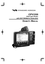
background image

CPV350

GPS Chart Plotter

with VHF FM Marine Transceiver

O

WNER

'

S

 M

ANUAL

Summary of Contents for CPV350

Page 1: ...CPV350 GPS Chart Plotter with VHF FM Marine Transceiver OWNER S MANUAL ...

Page 2: ...t 15 of the FCC Rules These limits are designed to provide reasonable protection against harmful interference when the equipment is operated in a commercial environment This equipment generates uses and can radiate radio frequency energy and if not installed and used in accordance with the instruction manual may cause harmful interference to radio communications Operation of this equipment in a re...

Page 3: ...e or towel and a cleaning spray Windex containing Isopropanol a normal spray cleaner sold for a PC screen for example PolaClear by Polaroid Fold the tissue or lens tissue into a triangular shape moisten the tip and use the index finger behind a corner to move the tissue across the surface in overlapping side to side strokes If the tissue is too wet a noticeable wet film will be left in its path an...

Page 4: ...3 9 NMEA Data Page 20 2 4 GPS ANTENNA 21 2 4 0 Mounting the GPS WAAS Smart Antenna 21 2 4 1 Mounting on a Pole 21 2 4 2 Flush Mounting 21 2 4 3 PA Horn Connections 22 2 5 SMART GPS CONNECTOR TABLE 22 2 6 BATTERY CONNECTIONS 22 2 7 OPTIONAL BLACK BOX FISH FINDER 23 2 8 OPTIONAL VHF EXTERNAL SPEAKER 23 3 C MAP MAX OVERVIEW 24 3 0 INTRODUCTION 24 3 1 INSERTING THE C CARD 25 4 MAP FUNCTIONS 26 4 0 NEW...

Page 5: ... 10 4 GOTO A ROUTE 53 10 4 0 By select Route 53 10 4 1 By Cursor key 53 10 5 OTHER SETTINGS IN ROUTE MENU 54 11 TRACKS 55 11 0 TRACKING 55 11 0 0 Saving and starting a new Track 56 11 0 1 Other Settings in Track Menu 56 11 1 USING THE TRIP LOG 57 11 1 0 Resetting the Trip Log 57 12 USER C CARD 58 12 0 USER C CARD MENU 58 12 0 0 Formatting the User C CARD 58 12 0 1 Transferring files to the optiona...

Page 6: ...OPERATING ON CHANNELS 13 AND 67 86 18 10 DUAL WATCH TO PRIORITY CHANNEL 86 18 11 SCANNING 86 18 11 0 Selecting the Scan Type 86 18 11 1 Memory Scanning M SCAN 87 18 11 2 Priority Scanning P SCAN 87 18 11 3 Priority Channel Set 88 18 12 PA FOG OPERATION 89 18 12 0 Operating the PA HAIL mode 89 18 12 1 Operating the FOG HORN mode 89 18 12 2 FOG ALERT TONE Frequency 91 18 13 INTERCOM OPERATION 91 18 ...

Page 7: ... 117 21 3 DSC RADIO SETUP MODE 118 22 VH 310 HANDSET OPERATION 119 22 0 VH 310 HANDSET CONTROLS 119 22 1 PA FOG OPERATION 122 22 1 0 Operating the PA Hailer 122 22 1 1 Operating the FOG Horn 122 22 2 INTERCOM OPERATION 111 22 2 0 Communication 122 22 2 1 Calling 123 22 3 MANUAL INPUTTING OF THE GPS LOCATION LAT LON 123 22 4 DSC RADIO SETUP MODE 124 22 4 1 Changing GPS Information to Vessel positio...

Page 8: ...t panel keys and LCD and a optional voice scrambler GPS chart plotter features include 7 inch 256 Color TFT sunlight viewable LCD display Screen Resolution 800x480 12 Channel GPS WAAS smart antenna Cartography C Map NT C Map MAX capable Customizable display windows Dual frequency fish finder capable FF520 required Split screen capability Worldwide background map showing detail up to 2 0 NM include...

Page 9: ...cket and mounting hardware Owner s Manual 1 2 OPTIONAL ACCESSORIES Black Box Fish Finder FF520 Dual Frequency Black Box Fish Finder 500W or 1000W depending on transducer connected 500W Transducers DST520 Nylon depth temp DST521 Transom mount depth temp speed DST523 Bronze depth temp DST525 In hull depth only DST526 Thruhull Depth speed temp with fairing block 1000W Transducers DST527 In hull depth...

Page 10: ...ocated at least 0 6 m 2 feet away from passengers in order to comply with the FCC RF exposure requirements 1 3 1 On Line Wattanty Registration Please visit www standardhorizon com to register the CPV350 Marine VHF It should be noted that visiting the Web site from time to time may be beneficial to you as new products are released they will appear on the Marine Division of Vertex Standard Web site ...

Page 11: ...c gov forms To obtain a form from the FCC call 888 225 5322 1 4 1 Radio Call Sign Currently the FCC does not require recreational boaters to have a Ship Radio Station License The USCG recommends the boats registration number and the state to be used 1 4 2 Canadian Ship Station Licensing You may need a license when traveling in Canada If you do need a license contact the nearest field office or reg...

Page 12: ...the two types of installation 2 1 BRACKET MOUNTING The CPV350 can be mounted using the supplied bracket Before installing ensure the area the CPV350 s bracket is mounted to is strong enough to support the weight of the CPV350 especially while under way After the location is found attach the mounting base to the area using the supplied hardware Figure 2 1 Installing CPV350 Bracket ...

Page 13: ...m the backing and apply the label to the mounting area 2 Drill a hole in one area of the cut area that will allow the blade of a jig saw to be inserted Insert and cut out the area on the panel using the jig saw 3 Remove the three screws affiex the grip and remove the grip from the CPV350 4 Next drill the four holes required to insert the CPV350 with the mounting studs 5 Install the mounting studs ...

Page 14: ...connections for AIS receiver and other NMEA devices 4 GPS Antenna Connects the GPS antenna to the CPV350 Only use the GPS Smart antenna supplied with the CPV350 5 External speaker Connects to the MLS 300 MLS 310 or any 8 Ohm 6Watt external speaker 6 PA Horn Connects to 220SW 240SW or any 4 Ohm 30W PA Speaker 7 DC INPUT CABLE Connects the radio to a DC power supply capable of delivering 12V DC 2 3 ...

Page 15: ...miles 2 3 2 Selecting a Marine VHF Antenna Marine antennas are made to radiate signals equally in all horizontal directions but not straight up The objective of a marine antenna is to enhance the signal toward the horizon The degree to which this is accomplished is called the antenna s gain It is measured in decibels dB and is one of the major factors in choosing an antenna In terms of effective r...

Page 16: ...stallation of the connector onto the coaxial cable refer to the figure below Figure 2 4 0 Installing the VHF antenna To get your coax cable through a fitting and into your boat s interior you may have to cut off the end plug and reattach it later You can do this if you follow the directions that come with the connector Be sure to make good soldered connections Figure 2 4 0 Installing the VHF anten...

Page 17: ... Figure 3 make a 1 2 30 mm hole in the wall then insert the Routing Cable into this hole Connect the Gasket and Mount Base to the Routing Cable Connector using the Nut 3 Drill the four Screw holes approx 2 mm on the wall then install the Mounting Base to the wall using four screws 4 Put the Rubber Cap on to the Nut The installation is now complete 5 Wires for an external speaker are provided on th...

Page 18: ...the key to until EXT SPK is shown and press the CALL SET key 5 Press the or key to select oF External speaker off or on External speaker on 6 Press the CALL SET key to save the selection 7 Press the 16 9 key to exit this mode VH 310 Procedure 1 Press and hold the CALL MENU key 2 Press the or key to select RADIO SETUP 3 Press the ENT key 4 Press the key to until EXT SPK is shown and press the ENT k...

Page 19: ...to intput of NMEA device Default is NMEA0183 with GLL RMB RMC and XTE sentences 8 Yellow NMEA Output Port 4 Connect autopilot Default is NMEA0183 with APA APB XTE COG and BOD sentences When the FF520 is connected port 2 input must be changed to FF520 To do this press MENU two times move the ShuttlePoint konb to highlight ADVANCED SETUP IN OUT CONNECTIONS PORT2 INPUT FF520 Figure 2 3 5 IN OUT CONNE...

Page 20: ...ed down by an external NMEA device Example Autopilot connected but the CPV350 but is not receiving NMEA data Usually the Autopilot will be connected to the yellow wire To check to see if the GPS chart plotter is transmitting the Autopilot sentences 1 Press MENU Move the ShuttlePoint knob to highlight NMEA DISPLAY and press ENT 2 Move the ShuttlePoint knob to highlight DATA and press ENT 3 The NMEA...

Page 21: ...cket This is no concern however as the antenna must be tightened until the antenna stops rotating NOTE The antenna cable can be cut and spliced to ease installation Care must be taken when reconnecting the antenna cable to protect from water and corrosion 2 4 2 Flush Mounting NOTE Before drilling holes it is recommended the antenna be positioned where the location is planned to be drilled cable co...

Page 22: ...Smart GPS NMEA Output Connect to Smart GPS Output 4 NC 5 NC 6 Black Yellow Battery Ground Connect to battery ground and Black wire of GPS Antenna 2 6 BATTERY CONNECTIONS CAUTION Reverse polarity connections will damage the radio 1 Connect the red power wire to a 13 8 VDC 20 power source Connect the black power wire to a negative ground 2 If an optional remote extension speaker is to be used refer ...

Page 23: ...r s Manual supplied with the Fish Finder for connections and operation When the FF520 is connected port 2 input must be changed to FF520 To do this press MENU two times move the ShuttlePoint konb to highlight ADVANCED SETUP IN OUT CONNECTIONS PORT2 INPUT FF520 Figure 2 7 IN OUT CONNECTION menu 2 8 OPTIONAL VHF EXTERNAL SPEAKER THE CPV350 has connections for an external VHF speaker for louder audio...

Page 24: ...ntation mode Flexi Zoom increased Under and Over Zoom between chart levels resulting in optimal scale display for any situation Dynamic Elevation Data optimized palettes for GPS chartplotters includes new NOAA palette Perspective View Real World perspective view of the chart updated real time during navigation MAX and NT NT C CARD coexistence When NT data and MAX data cover different areas the GPS...

Page 25: ...Page 25 CPV350 Open the door gently push the C CARD into the slot push the C CARD in as far as it will go then close the door Figure 3 1a Inserting C CARD Details ...

Page 26: ... selected zoom factor will be used at the next zoom in out To activate this function follow the procedure 1 Press MENU for two times Move the ShuttlePoint knob to highlight MAX FUNCTIONS and press ENT or move the ShuttlePoint knob to the right 2 Move the ShuttlePoint knob to highlight ZOOM TYPE and press ENT or move the ShuttlePoint knob to the right 3 The menu now shows two selections STANDARD or...

Page 27: ... side on the right side settings 4 0 2 Perspective View Chart data may be projected in perspective mode during navigation This function allows setting the panoramic View of the chart As the upper side of the map is more compressed than the lower side a wider map area is visible The perspective view allows showing more chart information immediately ahead and around the cursor Figure 4 0 2 Perspecti...

Page 28: ...e left until the chart page is shown 4 0 4 Safety Status Bar DSI Data Safety Indicator When Safety Status Bar is On a status bar with six boxes showing the status of certain functions is displayed Any warning or alarm condition is identified by the red color to indicate possible risk To activate this function follow the procedure 1 Press MENU two times Move the ShuttlePoint knob to highlight MAX F...

Page 29: ...clearing overlapping objects Dangers Red when Guardian Technology detects one of the following objects Land Inter tidal Depth Area Rocks Obstructions Shoreline Constructions Fishing Facility Wrecks Dragged area Diffusion area Mooring facilities Pingos and Production in stallations Caution Red when Guardian Technology detects cautionary or restricted area 4 0 5 Currents Prediction When enabled show...

Page 30: ...e the identification of cartographic objects or places around the map they can be the landscape layout nearby a harbor the shape of a bridge or of a buoy etc On some objects such as bridges the image associated can represent the Diagram representing the shape of the objects and the various characteristics length height type of bridge etc Figure 5 0 Pictures and Diagrams The pictures or diagrams ca...

Page 31: ...Info there will be the small camera icon on a corner of the square containing the object icon To see the picture press MENU when the object with a picture is highlighted When the picture is shown it is possible to fit it to screen by pressing ENT When the picture is shown it is possible to change the contrast by pressing ZOOM and moving the knob When the picture is shown it is possible to display ...

Page 32: ...changes the VHF channels To zoom in rotate the channel selector knob Clockwise up or to zoom out rotate the channel knob counter clockwise down When finished zooming press the ZOOM key Rotating the channel knob NOTE The GPS chartplotter contains a Worldwide background that allows you to zoom into 2 NM For more detail a C MAP NT MAX C CARD must be purchased and installed The ShuttlePoint knob The S...

Page 33: ... selected their labels are shown on the screen immediately above the keys the user can customize the function associated These keys allow quick selection to the many pages the GPS chartplotter has These keys can be customized to your preference however from the factory the keys are preprogrammed with the following pages From left to right CHART NAV HIGHWAY CELESTIAL NMEA DISPLAY LIST Press any of ...

Page 34: ...lePoint knob you will notice DST and BRG values in the Data window change This shows the Distance and Bearing from the GPS Fix of your vessel to the position of the Cursor 6 If the cursor is moved to the edge of the screen the GPS chartplotter will automatically pan in the desired direction 6 1 1 Cursor Vs Home Mode Cursor Mode When the cursor is shown on the Chart page this is called Cursor mode ...

Page 35: ...ENT or move the ShuttlePoint knob to the right Move the ShuttlePoint knob to the desired setting and press ENT or move the ShuttlePoint knob to the right 5 Press CLR until the menu disappears or an easier method is to press the ShuttlePoint knob to the left a few times 6 Move the cursor on the Chart page and see if the speed is to your liking 6 1 3 Changing the Ships Icon The cursor may be changed...

Page 36: ...e direction your vessel is traveling Figure 6 1 5 Course Up North Up menu 1 Press MENU two times Move the ShuttlePoint knob to highlight GENERAL SETUP and press ENT or move the ShuttlePoint knob to the right 2 Move the ShuttlePoint knob to highlight COURSE UP NORTH UP and press ENT or move the ShuttlePoint knob to the right 3 Another popup window will be shown with NORTH UP and COURSE UP move the ...

Page 37: ... offset for standard time For daylight saving time subtract one hour from the offset time Figure 6 2a Time Setup menu 1 Press MENU two times Move the ShuttlePoint knob to highlight GENERAL SETUP and press ENT or move the ShuttlePoint knob to the right 2 Move the ShuttlePoint knob to highlight TIME SETUP and press ENT or move the ShuttlePoint knob to the right 3 Move the ShuttlePoint knob to highli...

Page 38: ...m menu 1 Press MENU two times Move the ShuttlePoint knob to highlight ADVANCED SETUP and press ENT or move the ShuttlePoint knob to the right 2 Move the ShuttlePoint knob to highlight NAVIGATE and press ENT or move the ShuttlePoint knob to the right 3 Move the ShuttlePoint knob to highlight COORDINATE SYSTEM and press ENT or move the ShuttlePoint knob to the right 4 Move the ShuttlePoint knob to h...

Page 39: ...A Night and Sunlight Move the ShuttlePoint knob to the desired selection and press ENT or move the ShuttlePoint knob to the right 4 Press CLR or move the ShuttlePoint knob to the left to exit the menu and show the Chart page 6 5 SELECTING PAGES USING SOFT KEYS The Soft Keys located under the LCD are used to select the pages quickly without the need to go into the menu The default pages are CHART N...

Page 40: ...oosing date format MM DD YY or DD MM YY COURSE UP NORTH UP Selections are North Up The Top of the page is fixed to North Course Up The top of the page is orientated to the direction the vessel is heading KEYPAD BEEP Allows the beep produced when a key is pressed to be turned on or off UNITS OF MEASURE Units of Measure can be selected for Distance Speed Depth Altitude and Temperature NAV AIDS PRESE...

Page 41: ... moved a window is shown with the Lat Lon Distance and bearing from the vessels location to the cursor This selection allows the window to be turned off CURSOR POSITION The position of the cursor vessels location can be customized so it centered in the middle or centered on the bottom of the chart page The default is Bottom COG TIME LINE Is a line projected from the vessel icon which indicates the...

Page 42: ...e Service 7 Press CLR which will show the available Services at the location 8 Press CLR to show the actual position of the Services Figure 7 0 Port Services 7 1 OTHER AVAILABLE SEARCHES PORT BY NAME Searches and shows on the Chart page the list of all ports stored on the C CARD in alphabetic order PORT BY DISTANCE Searches and shows the list of all ports stored on the C CARD in distance order TID...

Page 43: ...he following picture Lakes Info icon Figure 7 2 0 Example of Lakes info When the cursor is placed over the icon the icons of the available services are shown Figure 7 2 0a Quick Info available services If you press ENT all available information about the cartographic point under the cursor will be shown See the next paragraph 7 2 1 Full Info On Lakes The following is an example of Full Info on Lak...

Page 44: ...Page 44 CPV350 To see the Fishing object press MENU when the Fishing object is highlighted On the screen appears Figure 7 2 1a Example of picture associated to the Fishing object ...

Page 45: ... You will notice a Mark is placed under the location of the Cursor and a popup window is shown with the exact Lat Lon of the Mark 3 If the position is incorrect press EDIT that will allow you to change the position Mark name icon type and color of the icon Vessel location Mark placed under Cursor Lat Lon of Mark DST BRG from vessel location 2 1 4 Press Soft Key to show the Marks Waypoint List to e...

Page 46: ...b up or down to select the first character 11 Move the ShuttlePoint knob to the right to select the next character 12 Repeat steps 10 and 11 until the desired position is shown Press ENT and CLR to store the Mark 8 1 0 Deleting a Mark or Waypoint Move the cursor over the Mark or Waypoint to delete Press DELETE A Warning popup window will be shown Select YES and press ENT 8 1 1 Moving a Mark or Way...

Page 47: ...n DELETE Delete the selected point DEL ALL Delete all stored points SEND Sends the stored points to a external device PC capable of listening to NMEA WPL sentence RECEIVE Receive the points from an external device PC that is capable of sending NMEA WPL sentence NOTE The SEND and RECEIVE functions are usually used by navigation programs running on a Personal Computer example Nobeltech Figure 8 2 Ma...

Page 48: ... to quickly start navigating to the Cursor Mark or Route GOTO CURSOR 1 Move the ShuttlePoint knob to the exact position you want to navigate to 2 Press GOTO and a GOTO popup window will be shown Figure 8 4 GO TO menu 3 Move the ShuttlePoint knob to highlight CURSOR and press ENT 4 The GPS chartplotter is now navigating from your current position to the location selected at step 1 Figure 8 4a Navig...

Page 49: ...ove the ShuttlePoint knob to highlight MARK and press ENT to show the Marks Wpt List 4 Move the ShuttlePoint to the highlight the desired Mark or Waypoint and press GOTO 5 You will notice a circle is drawn around the Icon Symbol This means the GPS chartplotter is now navigating to the point 6 Press CLR to switch to the Chart page or Highway page to start navigating to the point ...

Page 50: ...efficiently 1 On the Chart page press MARK MOB to start navigating back to the point 2 You will notice a MOB Mark will be laid on the Chart page and all navigation is referring back to this point 3 If the cursor is moved over the MOB Icon popup windows over Soft Keys will be shown allowing quick access to the Navigation or Highway pages 9 0 DELETING A MOB POINT 1 Move the ShuttlePoint knob until t...

Page 51: ...Press RTE You will notice another Waypoint is shown under the cursor and a line joins the starting Waypoint to the Second Waypoint Figure 10 0 Creating a Route using Waypoints 5 Repeat steps 3 and 4 until all Waypoints are entered into the Route NOTE At this point the Route is saved as ROUTE01 If you would like to save the Route under a specific name follow the remaining steps 6 To name the Route ...

Page 52: ...e steps in Creating a Route using Waypoints or Marks sections 10 2 CREATING A ROUTE USING MARKS ON THE CHART PAGE To create a Route containing Marks you first must create the Marks and show them on the Chart page 1 Move the ShuttlePoint knob over the top of a Mark that you wish to be the starting point in the Route and press RTE 2 Next move the ShuttlePoint knob until the cursor is over the Mark t...

Page 53: ...e Waypoint and press ENT 10 4 GOTO A ROUTE 10 4 0 By select Route 1 Move the ShuttlePoint knob to an open position no buoy warning etc under the cursor on the Chart page 2 Press GOTO to show the GOTO popup window 3 Move the ShuttlePoint knob to highlight ROUTE and press ENT 4 The SELECT ROUTE popup window will be shown 5 Move the ShuttlePoint knob to the highlight the desired Route and press ENT 6...

Page 54: ...e end of the Route COLOR Allows changing the color of the navigation lines between in leg in the Route REPORT The Route Report menu is useful to show details of the Waypoints contained within the Route This menu also allows you to enter in your average speed and fuel consumption and calculate the approximate fuel used when following the Route SEND Sends the stored points to a external device PC ca...

Page 55: ...e the ShuttlePoint knob to highlight TRACK and press ENT 3 Move the ShuttlePoint knob to highlight STEP UNIT and press ENT or move the ShuttlePoint knob to the right 4 Move the ShuttlePoint knob to highlight Dist or Time and press ENT or move the ShuttlePoint knob to the right Figure 11 Distance Units and Time Units 5 Move the ShuttlePoint knob to highlight DISTANCE or TIME step interval and press...

Page 56: ...press ENT or move the ShuttlePoint knob to the right to set On 6 Press CLR or move the ShuttlePoint knob to the left until the Chart page is shown 7 A new Track now will be laid down 11 0 1 Other Settings in Track Menu You will notice the Track menu has other selections TRACKING Allows turning on or off the tracking function ACTIVE TRACK This selection allows you to save a Track to one of the 5 Tr...

Page 57: ...o select the desired units of measure and press ENT or move the ShuttlePoint knob to the right 4 Press CLR or move the ShuttlePoint knob to the right until the selected page Chart Navigation Highway or NMEA Data Page is shown 11 1 0 Resetting the Trip Log Select the page with TRIP LOG in one of the data windows as setup in the Using the TRIP LOG section 1 Press and hold MENU move the ShuttlePoint ...

Page 58: ...ssist you to transfer the User Points Routes and Track history to the optional User C CARD 6 Type of data contained in the file Mark file Waypoint file File name Number of Selected file Information on stored User Points on Internal Memory Time of file creation Date of file creation 5 6 2 1 3 4 1 2 3 4 5 Figure 12 0 User C CARD Menu 12 0 0 Formatting the User C CARD 1 Press MENU Move the ShuttlePoi...

Page 59: ...s possible to load the data back into the GPS chartplotter using the following procedure 1 Press MENU Move the ShuttlePoint knob to highlight USER POINTS and press ENT 2 Move the ShuttlePoint knob to highlight USER C CARD and press ENT 3 Select the saved file from the User C CARD list by using the ShuttlePoint knob and press ENT 4 Move the ShuttlePoint knob to the left to highlight LOAD and press ...

Page 60: ... with optional F 520 connected F Figure 13 Screen display pages The pages can selected in one of two ways Selection by MENU Press MENU move the ShuttlePoint knob to highlight the desired Page in the Main Menu page and press ENT Figure 13a Screen display pages by MENU Selection by SOFT KEY Pressing any Soft Key under the display then press the Soft Key to show the desired page Figure 13b Screen dis...

Page 61: ...s and general text area 13 0 0 Window Selections The window on the right side of the Chart page is called the General Window and it may be edited customized or even changed to show a highway or compass tape FULL CHART None 2 LINES SMALL COMPASS GENERAL 1 LINE SMALL HIGHWAY 1 LINE LARGE Figure 13 0 0 Data window layout 1 To change press MENU two times Move the ShuttlePoint knob to highlight GENER A...

Page 62: ...arate dedicated RADAR display Tides Custom default mode The table below shows the selections for each mode 1 To change to one of the preprogrammed settings press MENU two times Move the ShuttlePoint knob to highlight MAP CONFIGURATIONS and press ENT or move the ShuttlePoint knob to the right 2 Move the ShuttlePoint knob to highlight DISPLAY MODE and press ENT or move the ShuttlePoint knob to the r...

Page 63: ... of the arrow denotes the strength of the current as follows When the GPS chartplotter receives a valid position fix the Tide icons are shown on the charts on the basis of the current date and time the screen displays and changes arrows as date time changes Seabed Type Turns the displaying of the Seabed type On or Off Ports Services Turns the displaying of Ports and Service icons On of Off Areas a...

Page 64: ...sing charts from above and below the current scale When this function is turned on you will notice the display may redraw 2 to 3 times to show all the details Chart Lock Sets On Off the Chart Lock option When Chart Lock is On the available zoom scales are only the ones containing cartographic data Instead when Chart Lock is Off it is possible to zoom down into zoom scales not covered by cartograph...

Page 65: ...p or down to choose the desired setting and press ENT to select and press CLR to store and exit the editing mode Figure 13 0 9 Customize the Data Windows NOTE Data window field on the NAVIGATION HIGHWAY GPS STATUS and NMEA pages may be customized in the above manner 13 1 CUSTOMIZING CHART SETTINGS 1 Press MENU two times Move the ShuttlePoint knob to highlight MAP CONFIGURA TIONS and press ENT or m...

Page 66: ... 3 Move the ShuttlePoint knob to highlight NAVIGATION PAGE and press ENT or move the ShuttlePoint knob to the right 4 Move the ShuttlePoint up or down to select COMPASS TAPE and press ENT 5 Press CLR or move the Shuttlpoint knob to the right until the Chart page is shown 4 2 1 6 7 3 5 3 2 4 9 8 Fix position Time Speed Over Ground Course Over Ground 5 1 Date Distance 6 7 Bearing to Destination 8 9 ...

Page 67: ...3 Highway page 13 4 CELESTIAL PAGE This page is useful for boaters that are concerned about the height of the water under a bridge or by fisherman that wish to know the tide and moon phase of a specific date Changing date 1 Press ENT and a popup window will be shown 2 Moving the ShuttlePoint knob up or down changes the digits and left and right selects the month day and year 3 Press CLR to exit an...

Page 68: ...lites GPS3D the GPS is receiving at least 3 Satellites WAAS 2D 3D the GPS is receiving a 2D or 3D position and the correction from the WAAS Satellite HDOP Horizontal Dilution of Precision VDOP Vertical Dilution of Precision 13 6 NMEA DISPLAY PAGE The GPS chartplotter is capable of displaying information in the customizable data windows from external NMEA devices Depth sounder Speed Log with temp W...

Page 69: ...sually the VHF Radio will be connected to the Green and Brown wires To check to see if the GPS chartplotter is transmitting the sentences 1 Press MENU Move the ShuttlePoint knob to highlight NMEA DISPLAY and press ENT 2 Move the ShuttlePoint knob to highlight DATA and press ENT 3 Connect the BLUE Wire on the GPS chartplotter to the junction of the Brown wire and the VHF wire The display should loo...

Page 70: ...l equipped with a DSC transceiver The CPV350 is capable of VHF Marine Radios with Digital Selective Calling are able to be interfaced with the GPS chartplotter which feeds GPS data to the VHF and listens for DSC calls from the VHF By connecting a few wires between the STANDARD HORIZON VHF and the GPS chartplotter it will receive 1 a vessel that has transmitted a DSC Distress call 2 a vessel that h...

Page 71: ...utes and Thousands of Minutes d ddd mm mm Degrees Minutes and Hundredths of Minutes e ddd mm ss Degrees Minutes and Seconds default Map Datum Allows selection of Map Datums The default Datum is WGS84 as C MAP cartography has been compiled using the WGS84 Datum Map Orientation Resolution Sets the angle the vessel has to change before the chart is redrawn The default setting is 30 degrees Example if...

Page 72: ...d Magnetic Variation Auto or Manual see next paragraph to compute True bearing Variation Allows the user to select Auto or Manual When Auto mode is selected the GPS chartplotter computes the offset by the current GPS fixed location Manual mode allows the user to enter in a magnetic variation that is applied in the True conversion Calibration This function allows a user to enter in the offset for a...

Page 73: ...ger The name of each new dangerous object found is reported in the warning window In the Grounding Alarm Report page the relative item has a tick marker next to it to identify the dangerous object currently detected If in the next search cycle the same objects are found again the alarm window will not be shown Instead if in the next searches the objects found before are no longer detected their re...

Page 74: ...bout the targets is being received by AIS Receiver and displayed on the screen CPA Closest Point of Approach is the closest distance that will be achieved between your vessel and the tracked target based on your vessel s speed and direction and the target s speed and direction CPA Limit This is the distance from your vessel that a target may reach before a target is deemed a threat CPA Alarm Occur...

Page 75: ...scribed in the following table Display Turns the display of AIS Targets overlay on the cartography On or Off The default setting is On Activation Range Defines the range from the fix within which the AIS Target becomes active The values allowed are from 0 1 to 20 Nm The default setting is 5 Nm CPA Alarm Turns On or Off the alarm The default setting is On CPA Limit The values allowed are from 0 1 t...

Page 76: ...cing the cursor over a AIS Target icon the following information is displayed Vessel Name MMSI number Radio Call Sign SOG COG CPA and TCPA values NOTE The selected AIS Target icon is surrounded by a square frame when user places the cursor over the icon ...

Page 77: ...ilable are Figure 16 Weather data package 16 0 C WEATHER SERVICE MENU To select the menu 1 Press MENU two times Move the ShuttlePoint knob to highlight C MAP WEATHER SERVICE and press ENT or move the ShuttlePoint knob to the right The C Weather menu is shown on the screen the items are described in the following paragraphs 16 0 0 Download Allows to connect the software to the C MAP weather server ...

Page 78: ...nd to change date and time of the forecast preview The following functions are available Panning default usage of the cursor key is the normal panning function Zoom in out zoom in out functions are allowed as usual by using ZOOM Set of date and time DATE to modify date and time values Layer selection LAYER to cycle of the weather layers Exit EXIT to close the weather prediction page 16 0 3 Real Ti...

Page 79: ...to highlight a selection and press the ENT key to select the function Pressing MENU two times selects the Setup Menu The ENT key Press ENT to select the desired menu function or to confirm selection The CLR key Press CLR to exit from menu or data windows or to leave a menu without making changes to abort selected function or to step backward from a selection made in the menu The Channel knob The r...

Page 80: ...o the Priority channel and listen for communications Refer to section 18 10 DUAL WATCH TO PRIORITY CHANNEL for details The SCAN MEM key Press SCAN MEM to start and stop the scanning of programmed channels Refer to section 18 11 SCANNING for details Secondary use To memorized a channel into scan memory select the channel and press and hold SCAN MEM until MEM is shown in the VHF Radio window on the ...

Page 81: ...reble and bass controls on a stereo 1 Press MENU two times Move the ShuttlePoint knob to highlight RADIO SETUP and press ENT or move the ShuttlePoint knob to the right 2 Move the ShuttlePoint knob to highlight VHF SETTING and press ENT or move the ShuttlePoint knob to the right 3 Move the ShuttlePoint knob to highlight AF SETUP and press ENT or move the ShuttlePoint knob to the right 4 Move the Sh...

Page 82: ... on the microphone TX indicator will appear in the VHF Radio window on the display 4 Speak slowly and clearly into the microphone 5 When the transmission is finished release PTT NOTE The CPV350 is supplied with a noise canceling microphone The oval slot labeled MIC should be positioned within 1 2 inch 1 3 cm from the mouth for optimum performance 18 2 TRANSMIT TIME OUT TIMER TOT When PTT on the mi...

Page 83: ...nistration sends a weather alert accompanied by a 1050 Hz tone and subsequent weather report on one of the NOAA weather channels When the Weather Alert feature is enabled see section 18 5 3 Customizing Weather Alert the transceiver is capable of receiving this alert if the following is performed 1 Program NOAA weather channels into the transceiver s memory for scanning Follow the same procedure as...

Page 84: ...de The WX alert mode can be set to On SCAN the CPV350 will only alert when in scan mode On WX the alert will only sound if the radio is on a receiving weather channel On SCAN WX the CPV350 will only alert when a receiving channel is programmed and scanned Off disables the Weather alert function 5 Press ENT or move the ShuttlePoint to the right to store the selected setting 6 Press CLR until the me...

Page 85: ...conds but may be repeated 3 times at 2 minute intervals Prior to making contact with another vessel refer to the channel charts in this manual and select an appropriate channel for communications after initial contact For example Channels 68 and 69 are some of the channels available to non commercial recreational boaters Monitor your desired channel in advance to make sure you will not be interrup...

Page 86: ... the assigned Priority channel By default the priority channel is set to 16 however the priority channel may be changed by referring to section 18 11 3 Priority Channel Set 1 Adjust SQL until the background noise disappears 2 Select the channel you wish to dual watch to Priority channel by rotating the channel knob 3 Press DW 4 The CPV350 will scan between Priority channel and the channel that was...

Page 87: ...play 5 To start scanning just press SCAN MEM momentarily M SCAN appears in the VHF Radio window on the display Scanning will proceed from the lowest to the highest programmed channel number and will stop on a channel when a transmission is received 6 The channel number will blink during reception 7 To stop scanning press 16 9 or WX 18 11 2 Priority Scanning P SCAN In the default setting Channel 16...

Page 88: ...he ShuttlePoint knob to the right 2 Move the ShuttlePoint knob to highlight VHF SETTINGS and press ENT or move the ShuttlePoint knob to the right 3 Move the ShuttlePoint knob to highlight PRIORITY CHANNEL SET and press ENT or move the ShuttlePoint knob to the right 4 Move the ShuttlePoint knob to select USA INTL or CAN and press ENT or move the ShuttlePoint knob to the right 5 Move the ShuttlePoin...

Page 89: ...h the PTT pressed rotate the Channel knob to control the PA Volume level The AF output level can be set from 0 to 30 watts 4 To exit the PA HAIL mode press MENU and move the ShuttlePoint knob to highlight Exit Public Address then press ENT 5 To adjust the listen back volume rotate the Channel knob when the PTT is not pressed 18 12 1 Operating the FOG HORN mode Operator can select from Underway Sto...

Page 90: ...second blasts separated by 2 seconds evey 120 seconds One 5 second blasts followed by two 1 second blasts separated by 2 seconds evey 120 seconds One 5 second blasts followed by three 1 second blasts separated by 2 seconds evey 120 seconds One 11 second rings evey 60 seconds Motor vessel underway and making way Motor vessel underway but stopped not making way Sailling vessel underway fish ing vess...

Page 91: ...allows intercom communications Refer to section 21 2 INTERCOM OPERATION for CMP25 RAM Microphone or section 22 2 INTERCOM OPERATION for VH 310 Handset 1 Press MENU Move the ShuttlePoint knob to highlight Intercom then press ENT 2 If your CPV350 is equipped with two CMP25 RAM Mic s or VH 310 Handset INTERCOM popup window appears on the display select the station you wish to communicate Ram1 Ram2 or...

Page 92: ...b to the right 5 Move the ShuttlePoint knob to highlight CH NO and press ENT or move the ShuttlePoint knob to the right 6 Move the ShuttlePoint knob to select the operating channel you wish to setup the Voice Scrambler and press ENT 7 Move the ShuttlePoint knob to highlight SCRAMBLER and press ENT or move the ShuttlePoint knob to the right 8 Another popup window will be shown with On and Off move ...

Page 93: ...play 3 If a channel is not set for the voice scrambler the display will be as shown in the illustration at the right VS will disappear from the display 4 If a voice scrambler is canceled temporarily in the SETUP menu the display will be as shown in the illustration at the right 5 Monitor the channel before transmitting 6 Transmit the voice message The signal sent will be scrambled ...

Page 94: ...has also been designated as part of the Global Maritime Distress and Safety System GMDSS It is planned that DSC will eventually replace aural watches on distress frequencies and will be used to announce routine and urgent maritime safety information broadcasts This system allows mariners to instantly send a distress call with GPS position when connected to the transceiver to the Coast Guard and ot...

Page 95: ...e the ShuttlePoint knob to the right to step to the next number 5 Repeat step 6 to set your MMSI up to nine digits 6 When finished programming the number press the ENT to store the number in memory 7 Press CLR until the menu disappears or an easier method is to move the ShuttlePoint knob to the left a few times Figure 19 1 DSC SETTINGS menu 19 2 DSC DISTRESS CALL The CPV350 is capable of transmitt...

Page 96: ...re of Distress categories Undesignated Fire Flooding Collision Grounding Capsizing Sinking Adrift Abandoning Piracy MOB 1 Lift the red spring loaded DISTRESS cover and press DISTRESS The DISTRESS ALERT popup window will appear on the display 2 Move the ShuttlePoint knob to the up or down or turn the Channel knob to select the desired nature of distress category 3 Press and hold DISTRESS The radios...

Page 97: ...e a potential problem that may lead to a distress situation This call is the same as saying PAN PAN PAN on channel 16 SAFETY Call Used to transmit boating safety information to other vessels This message usually contains information about an overdue boat debris in the water loss of a navigation aid or an important meteorological message This call is the same as saying Securite Securite Securite 19...

Page 98: ...ar phones telephone directory 1 Press MENU two times Move the ShuttlePoint knob to highlight RADIO SETUP and press ENT or move the ShuttlePoint knob to the right 2 Move the ShuttlePoint knob to highlight DSC SETTINGS and press ENT or move the ShuttlePoint knob to the right 3 Move the ShuttlePoint knob to highlight INDIVIDUAL DIRECTORY and press ENT or move the ShuttlePoint knob to the right 4 Move...

Page 99: ...ler id on a cellular phone 1 Press MENU two times Move the ShuttlePoint knob to highlight RADIO SETUP and press ENT or move the ShuttlePoint knob to the right 2 Move the ShuttlePoint knob to highlight DSC SETTINGS and press ENT or move the ShuttlePoint knob to the right 3 Move the ShuttlePoint knob to highlight INDIVIDUAL REPLY and press ENT or move the ShuttlePoint knob to the right 4 A popup win...

Page 100: ... menu The CPV350 has the capability to turn off the ringer for Individual Group and DSC polling calls 1 Press MENU two times Move the ShuttlePoint knob to highlight RADIO SETUP and press ENT or move the ShuttlePoint knob to the right 2 Move the ShuttlePoint knob to highlight DSC SETTINGS and press ENT or move the ShuttlePoint knob to the right 3 Move the ShuttlePoint knob to highlight RINGER OUTPU...

Page 101: ...Channel knob to select the Individual you want to contact 4 Press ENT then turn the Channel knob to select the operating channel you want to communicate on and press ENT 5 Press ENT again to transmit the individual DSC Call or press the CLR key to cancel the call After INDIVIDUAL CALL is transmitted the transceiver will wait 8 seconds for the acknowledgment If the reply signal is not received the ...

Page 102: ... CALL is transmitted the transceiver will wait 8 seconds for the acknowledgment If the reply signal is not received the transceiver will transmit again 10 After the second INDIVIDUAL CALL is transmitted if the reply signal is not received the display will be as shown in the illustration on the right To send the call again press ENT or to exit the mode press CLR 11 When an individual call acknowled...

Page 103: ...ENT or move the ShuttlePoint knob to the right 3 Move the ShuttlePoint knob to highlight INDIVIDUAL REPLY MESSAGE and press ENT or move the ShuttlePoint knob to the right 4 A popup window will be shown with Able to Comply or Unable to Comply move the ShuttlePoint knob to the desired selection and press ENT or move the ShuttlePoint knob to the right 5 Press CLR until the menu disappears or an easie...

Page 104: ...bottom edge of the display 2 Press NEXT to change the menu Tabs to another Tabs 3 Press DSC LOG to appear DSC LOG popup window on the display 4 Move the ShuttlePoint knob to the up or down or turn the Channel knob to select the category DISTRESS or DSC CALL to be deleted 5 Press ENT to review details for the selected category 6 Move the ShuttlePoint knob to the up or down to select the station you...

Page 105: ... knob to highlight GROUP DIRECTORY then press ENT 4 Move the ShuttlePoint knob to highlight NEW then press ENT 5 Move the ShuttlePoint knob to up or down to scroll through the first letter of the name of the vessel or person you want to reference in the group MMSI number 6 Move the ShuttlePoint knob to the right to store the first letter in the name and step to the next letter to the right 7 Repea...

Page 106: ... of the display 2 Press GROUP to show DIRECTORY popup window on the display 3 Move the ShuttlePoint knob to the up or down or turn the Channel knob to select MANUAL then press ENT to show the MMSI INPUT window on the display 4 Move the ShuttlePoint knob to up or down to scroll through numbers 0 9 to enter the desired number and move the ShuttlePoint knob to the right to move one space to the right...

Page 107: ...tting up the Individual Position Call Directory to enter information into the individual directory 19 7 0 Setting up Position Reply The CPV350 can be set up to automatically or manually send your position to another vessel This selection is important if you are concerned about someone polling the position of your vessel that you may not want to In the manual mode you will see the MMSI or persons n...

Page 108: ...ob to select POLLING and press ENT or move the ShuttlePoint knob to the right 5 A popup window will be shown with On or Off move the ShuttlePoint knob to select Off and press ENT or move the ShuttlePoint knob to the right 6 Press CLR until the menu disappears or an easier method is to move the ShuttlePoint knob to the left a few times If you wish to return to enabling the ringer tone just repeat t...

Page 109: ...ress POSITION REQUEST to show DIRECTORY popup window on the display 3 Move the ShuttlePoint knob to the up or down or turn the Channel knob to select MANUAL then press ENT to appear MMSI INPUT window on the display 4 Move the ShuttlePoint knob to up or down to scroll through numbers 0 9 to enter the desired number and move the ShuttlePoint knob to the right to move one space to the right Repeat th...

Page 110: ...e is similar to Position Request however instead of requesting a position of another vessel this function allows you to send your position to another vessel 19 8 0 Setting up a Position Send Ringer The CPV350 has the capability to turn off the Position Send ringer 1 Press MENU two times Move the ShuttlePoint knob to highlight RADIO SETUP and press ENT or move the ShuttlePoint knob to the right 2 M...

Page 111: ...r below the display 2 Press POSITION REQUEST to show DIRECTORY popup window on the display 3 Move the ShuttlePoint knob to the up or down or turn the Channel knob to select MANUAL then press ENT to appear MMSI INPUT popup window on the display 4 Move the ShuttlePoint knob to up or down to scroll through numbers 0 9 to enter the desired number and move the ShuttlePoint knob to the right to move one...

Page 112: ...ir location to the CPV350 the following will happen 1 When the call is received a ringing sound will be produced and the RECEIVED DSC CALL popup window will open 2 Press the any key to stop the alarm 3 Press ENT to shows the position of the calling vessel on the GPS Chart of the radio display ...

Page 113: ... the ShuttlePoint knob to the right 5 Move the ShuttlePoint knob to highlight CH NO and press ENT or move the ShuttlePoint knob to the right 6 Move the ShuttlePoint knob to select the operating channel you wish change the channel name and press ENT 7 Move the ShuttlePoint knob to highlight NAME and press ENT or move the ShuttlePoint knob to the right 8 Move the ShuttlePoint knob to up or down to s...

Page 114: ...and press ENT or move the ShuttlePoint knob to the right 4 Move the ShuttlePoint knob to select the Unit MAIN RAM1 or RAM2 to be named and press ENT or move the ShuttlePoint knob to the right 5 Move the ShuttlePoint knob to up or down to scroll through the first letter of the unit name 6 Move the ShuttlePoint knob to the right to enter the first character and step to the next letter to the right 7...

Page 115: ...ween high and low power When the H L key is pressed while the transceiver is on channel 13 or 67 the power will temporarily switch from LO to HI power until the PTT is released The H L key does not function on transmit inhibited and low power only channels UP DOWN KEY These keys are used to select channels adjust the volume and squelch level and to choose the item selection of different functions ...

Page 116: ...hannel Group NOTE If position is displayed this icon will be hidden DISTRESS KEY Used to send a DSC Distress Call To send the distress call refer to section 19 2 0 Transmitting a DSC Distress Call 21 1 PA FOG OPERATION The RAM is capable of controlling the 30W Public address 4 fog horns bells and whistles 21 1 0 Operating the PA Hailer 1 Press and hold the NAV key then select PUBLIC ADRESS with th...

Page 117: ...mode press and hold down the NAV key again 21 2 INTERCOM OPERATION 21 2 0 Communication 1 Press and hold the DW key while in the RADIO mode the mode is changed to INTERCOM mode When the INTERCOM operation is activated IC is displayed on the RAM Mic and VH 310 Handset and INTERCOM is displayed on the CPV350 2 Press the PTT switch TALK is displayed NOTE A warning beep is emitted when the RAM Mic PTT...

Page 118: ...enu appears 2 Press the UP DOWN key to select RADIO SETUP or DSC SETUP menu 3 Press the CALL SET key then select the menu item you wish to work on by pressing the UP DOWN key 4 Press the CALL SET key 5 Press the UP DOWN key to change the value or condition for the menu item then press the CALL SET key to save the new setting 6 Press the UP DOWN key to select EXIT then press the CALL SET key to ret...

Page 119: ...RESS key Used to send a DSC Distress Call To send the distress call refer to section 19 2 0 Transmitting a DSC Distress Call VOL key Activates the volume adjusting mode Press this key to activate the volume adjusting mode Press the or to adjust the volume NOTE When the VH 310 handset is removed from the cradle the speaker audio will be automatically reduced so not to damage your hearing When the V...

Page 120: ...Secondary use Press the F key first then press the 1 DIM key to access the LCD Dimmer menu 2 MEM Key When in radio mode this key is used to directly select channel digit 2 in a channel number Secondary use Press the F key first then press the 2 MEM key memorize the selected channel into the transceiver scan memory for scanning When repeat the same procedures F 2 MEM will delete the channel from th...

Page 121: ...22 1 PA FOG OPERATION for details 8 PA Key When in radio mode this key is used to directly select channel digit 8 in a channel number Secondary use Press the F key first then press the 8 PA key available to operate the 30 Watt PA function Refer to section 22 1 PA FOG OPERATION for details 9 FOG Key When in radio mode this key is used to directly select channel digit 9 in a channel number Secondary...

Page 122: ...vate the FOG HORN menu 2 Select the one of the eight functions described above with the or key and press the ENT key 3 On the Horn and Siren modes press the PTT switch to activate the tone through the HAIL PA speaker Press the or keys to adjust the Audio output level The level can be set from 0 to 30W 4 To adjust the listen back volume while in listenback mode press the VOL Key then press the or k...

Page 123: ...st or Position Send will contain the manually entered position 1 Press and hold down the CALL MENU key until Radio Setup menu appears 2 Press the key to select DSC SETUP menu 3 Press the ENT key then select POS INPUT with the key 4 Press the ENT key then enter the your local time from the keypad by the 24 hour system on the UTC time 5 Enter the Latitude of your vessel location xx xx xx by the keyp...

Page 124: ...n the CALL MENU key until RADIO SETUP menu appears 2 Press the key to select RADIO SETUP or DSC SETUP menu 3 Press the ENT key then select the menu item you wish to work on by pressing the key 4 Press the ENT key 5 Press the key to change the value or condition for the menu item then press the ENT key to save the new setting 6 Press the key to select EXIT then press the ENT key to return to the no...

Page 125: ...he data entered then press the 16 9 key to exit this menu and return to radio operation mode 22 4 2 External Speaker AF Selection The AF SELECT menu allows you to set the audio output level of the VH 310 s External Speaker to fixed regardress the VOL level setting of the VH 310 which is useful to the case when use with the amplified speaker such as the Standard Horizon MLS 310 1 Press and hold dow...

Page 126: ... the unlikely event of serious problems please contact your Dealer or our repair facility Address and phone numbers for this facility as well as warranty information are contained in section 25 WARRANTY 23 0 REPLACEMENT PARTS Occasionally an owner needs a replacement mounting bracket or knob These can be ordered from our Parts Department by writing or calling Marine Division of Vertex Standard US ...

Page 127: ...e status If after pressing PWR for at least 3 seconds the GPS chartplotter does not turn Off turn Off the voltage The GPS chartplotter screen becomes very dark after a long exposure to direct sunlight The internal temperature is very high Control the contrast Protect the GPS chartplotter from direct sunlight The GPS chartplotter does not respond to any command The GPS chartplotter may be in an unp...

Page 128: ...rs alpha is not indicated but the proper channel is selected based on the U I C setting 3 Bridge to Bridge channels for example Channel 13 are for use by bridge operators on intercoastal waterways and rivers It is also used by marine vessels in the vicinity of these bridges for navigation and for communicating with the bridge operators Note that a limit of 1 Watt is specified for these channels Se...

Page 129: ...hip Navigation Safety Bridge to bridge 14 X X X S 156 700 Port operation VTS in selected areas 15 X S 156 750 Environmental Receive only 15 X X S 156 750 Commercial non commercial ship movement 1 W 16 X X X S 156 800 International Distress Safety and Calling 17 X X X S 156 850 State Controlled 1 W 18 X D 156 900 161 500 Port operation ship movement 18A X X S 156 900 Commercial 19 X D 156 950 161 5...

Page 130: ...l Used for Bridge to bridge communications in lower Mississippi River Inter ship only Canada Commercial fishing S R 68 X X X S 156 425 Non commercial Recreational 69 X X X S 156 475 US Non commercial Recreational Canada Commercial fishing only International Inter ship Port opertions and Ship movement 70 X X X S 156 525 Digital selective calling voice communications not allowed 71 X X X S 156 575 U...

Page 131: ... 161 875 Public Correspondence Marine Operator 86 X X X D 157 325 161 925 Public Correspondence Marine Operator 87 X X X D 157 375 161 975 Public Correspondence Marine Operator 88 X X X D 157 425 162 025 Public Correspondence ship to coast 88A X S 157 425 Commercial Inter ship Only WX01 X X X D 162 550 Weather receive only WX02 X X X D 162 400 Weather receive only WX03 X X X D 162 475 Weather rece...

Page 132: ...ransmit Channel designator Carrier frequency MHz Points of communi cation Intership and between coast and ship unless other wise iandicated Coast transmit Ship transmit Channel designator Carrier frequency MHz Points of communi cation Intership and between coast and ship unless other wise iandicated Coast transmit 1 156 050 MHz and 156 175 MHz are available for port operations and commercial commu...

Page 133: ...ates Canada border in the area of the Puget Sound and the Strait of Juan de Fuca its approaches the Great Lakes and the St Lawrence Seaway 157 425 MHz is available for intership and commercial communications Outside Puget Sound area and its approaches and the Great Lakes 157 425 MHz is also available for communications between commercial fishing vessels and associated aircraft while engaged in com...

Page 134: ...emory can be erased and the default setting restored RAM Test To verify the integrity of the RAM If on the screen the message ERROR appears the RAM is physically damaged Contact your Dealer or STANDARD HORIZON RAM Clear To clear internal memory If the GPS chartplotter exhibits unusual operations or appears to be malfunctioning it may be possible to correct the problem by clearing RAM This operatio...

Page 135: ...ion finding instrument this test should help determine the problem Change Parameters To change the parameters of the serial interface This menu allows to select the Port Signal Source the Baud Rate the Data Bits Word Length the Parity the Stop Bits Input Data Display To allow the GPS chartplotter to act as a computer terminal and display the incoming data exactly as it is received If the data disp...

Page 136: ... a division of Vertex Standard Attention Marine repairs 10900 Walker Street Cypress CA 90630 Include proof of purchase indicating model serial number and date of purchase STANDARD HORIZON will return the Product to the purchaser freight prepaid Products purchased prior to January 1 1991 will bear the STANDARD HORIZON warranty terms in effect prior to that date In the event of a defect malfunction ...

Page 137: ...e Product and ancillary equipment as a whole under this warranty STANDARD HORIZON reserves the right to make changes or improvements in Products during subsequent production without incurring the obligation to install such changes or improvements on previously manufactured Products The implied warranties which the law imposes on the sale of this Product are expressly LIMITED in duration to the tim...

Page 138: ...ion to the warranty STANDARD HORIZON includes a lifetime flat rate and customer loyalty programs to provide service after the warranty period has expired If you wish to obtain the flat rate price for out of warranty repair you must include the information on the Owner s Record with the unit when you return it to your Dealer or to STANDARD HORIZON Lifetime Flat Rate Service Program For the original...

Page 139: ...Page 139 CPV350 NOTE ...

Page 140: ...ncy Stability 0 0005 FM Hum and Noise 50dB 27 0 2 RECEIVER Sensitivity 0 25 µV 12 dB SINAD 0 28 µV 12 dB SINAD 70CH Receiver Squelch Sensitivity 0 15 µV Selectivity TYP 80 dB Spurious and Image Rejection 80 dB IntermodulationandRejectionat12dBSINAD Audio output 4 5 W Frequency Stability 0 0005 DSC format Class D EN301 025 V1 2 NMEA input Output Output DSC DSC Input GLL GGA RMC GNS Hailer power 30 ...

Page 141: ...mm on flagpole mount Weight without cable 5 6 oz 160 g Cable GPH 10 white 15 meter 8x28AWG cable with 6 pins female connector 27 1 1 ELECTRICAL CHARACTERISTICS Input Voltage 10 VDC to 35 VDC unregulated Input Current 112 mA 12 VDC 60 mA 24 VDC 45 mA 35 VDC GPS Receiver Sensitivity 145 dBW minimum 27 1 2 GPS PERFORMANCE Receiver WAAS North America EGNOS Europe MSAS Asia Geodetic Datum WGS84 Channel...

Page 142: ...istance from your current position to a Destination point ETA Estimated Time of Arrival GPS Constellation The Global Positioning System GPS is a space based radio navigation system consisting of a constellation of satellites and a network of ground stations used for monitoring and control A minimum of 24 GPS satellites orbit the Earth at an altitude of approximately 11 000 miles providing users wi...

Page 143: ...ts or 0 62 MPH VMG It is the destination closing Velocity The VMG is calculated using the current speed of the vessel SOG and the difference between the current vessel course and the bearing to the Destination WAAS 2D 3D The GPS is receiving a 2D or 3D position and the correction from the WAAS Satellite WAAS consists of approximately 25 ground reference stations positioned across the United States...

Page 144: ...eadquarters 10900 Walker Street Cypress CA 90630 U S A www standardhorizon com E M 0 1 6 N 1 0 0 Copyright 2006 VERTEX STANDARD CO LTD All rights reserved No portion of this manual may be reproduced without the permission of VERTEX STANDARD CO LTD 0603b 0E ...

Reviews: