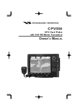
background image

CPV550

GPS Chart Plotter

with VHF FM Marine Transceiver

O

WNER

'

S

 M

ANUAL

Summary of Contents for CPV550

Page 1: ...CPV550 GPS Chart Plotter with VHF FM Marine Transceiver OWNER S MANUAL ...

Page 2: ... This equipment generates uses and can radiate radio frequency energy and if not installed or used in accordance with the instructions may cause harmful interference with radio communications There is no guarantee that interference will not occur in a particular instance If this equipment does cause harmful interference to other equipment try to correct the problem by relocating the equipment Cons...

Page 3: ...e and a cleaning spray containing Isopropanol a normal spray cleaner sold for the PC screen for example PolaClear by Polaroid Fold the tissue or lens tissue into a triangular shape moisten the tip and use the index finger behind a corner to move the tissue across the surface in overlapping side to side strokes If the tissue is too wet a noticeable wet film will be left in its path and you will nee...

Page 4: ...a Pole 19 2 4 2 Flush Mounting 19 2 4 3 SMART GPS Connector Table 20 2 5 PA HORN CONNECTIONS 20 2 6 NMEA CONNECTIONS 20 2 6 0 Output Sentences 21 2 6 1 Input Sentences 21 2 6 2 Cables 21 2 6 3 I O Connector Table 21 2 6 4 AIS Receiver Setup 21 2 7 FF520 FISH FINDER SETUP 22 2 7 0 AUX Connector Table 22 2 8 OUTPUTTING NMEA TO A PERSONAL COMPUTER 23 2 8 0 Serial PC Connection 23 2 9 NMEA DATA PAGE 2...

Page 5: ...1 8 3 Creating a NEW MARK with the MARKS WAYPOINTS LIST 51 8 4 GOTO 52 8 5 GOTO MARK 53 9 MAN OVER BOARD MOB FUNCTION 54 9 0 DELETING A MOB POINT 54 10 ROUTES 55 10 0 CREATING A ROUTE USING WAYPOINTS 55 10 1 MAKING ADDITIONAL ROUTES 56 10 2 CREATING A ROUTE USING MARKS ON THE CHART PAGE 56 10 3 INSERTING A WAYPOINT INTO A ROUTE 57 10 4 GOTO A ROUTE 57 10 4 0 By select Route 57 10 4 1 By Cursor key...

Page 6: ...OAA Weather Alert Test 88 18 5 3 Customizing NOAA Weather Alert 88 18 6 EMERGENCY CHANNEL CHANNEL 16 USE 88 18 7 CALLING ANOTHER VESSEL CHANNEL 16 OR 9 89 18 8 MAKING TELEPHONE CALLS 89 18 9 OPERATING ON CHANNELS 13 AND 67 90 18 10 DUAL WATCH TO PRIORITY CHANNEL 90 18 11 SCANNING 90 18 11 0 Selecting the Scan Type 90 18 11 1 Memory Scanning M SCAN 91 18 11 2 Priority Scanning P SCAN 91 18 11 3 Pri...

Page 7: ...121 21 2 INTERCOM OPERATION 121 21 2 0 Communication 121 21 2 1 Calling 121 21 3 DSC RADIO SETUP MODE 122 22 VH 310 HANDSET OPERATION 123 22 0 VH 310 HANDSET CONTROLS 123 22 1 PA FOG OPERATION 126 22 1 0 Operating the PA Hailer 126 22 1 1 Operating the FOG Horn 126 22 2 INTERCOM OPERATION 126 22 2 0 Communication 126 22 2 1 Calling 127 22 3 MANUAL INPUTTING OF THE GPS LOCATION LAT LON 127 22 4 DSC...

Page 8: ...d Worldwide background showing C MAP NT MAX detail up to 2 0 NM y 16 Channel GPS WAAS Smart antenna bracket and flush mounting hardware included y 3000 Waypoints Marks 50 Routes storage y User selectable data fields y NMEA Data pages y 4 NMEA Outputs and 4 Inputs y 3 year limited warranty lifetime flat rate Marine VHF features include y Commercial grade ITU Class D VHF transceiver y Complete Digit...

Page 9: ...ack Box Fish Finder 500W or 1000W depending on transducer connected 500W Transducers DST520 Nylon depth temp DST521 Transom mount depth temp speed DST523 Bronze depth temp DST525 In hull depth only DST526 Thruhull Depth speed temp with fairing block 1000W Transducers DST527 In hull depth only DST528 Bronze thru hull depth temp Radar Antennas Contact Standard Horizon for details Hailing horns 220SW...

Page 10: ...e antenna must be located at least 0 6 m 2 feet away from passengers in order to comply with the FCC RF exposure requirements 1 3 1 On Line Wattanty Registration Please visit www standardhorizon com to register the CPV550 It should be noted that visiting the Web site from time to time may be beneficial to you as new products are released they will appear on the Marine Division of Vertex Standard W...

Page 11: ... To obtain a form from the FCC call 888 225 5322 1 4 1 Radio Call Sign Currently the FCC does not require recreational boaters to have a Ship Radio Station License The USCG recommends the boats registration number and the state to be used 1 4 2 Canadian Ship Station Licensing You may need a license when traveling in Canada If you do need a license contact the nearest field office or regional offic...

Page 12: ...llations 2 1 BRACKET MOUNTING The CPV550 can be mounted using the supplied bracket Before installing ensure the area the CPV550 s bracket is mounted to is strong enough to support the weight of the CPV550 especially while under way especially while under rigorous conditions After the location is found attach the mounting base to the area using the supplied hardware Figure 2 1 Installing GPS Chart ...

Page 13: ...on is found peal the template label from the backing and apply the label to the mounting area 2 Drill a hole in one area of the cut area that will allow the blade of a jig saw to be inserted Insert and cut out the area on the panel using the jig saw 3 Next drill the four holes required to insert the CPV550 with the mounting studs 4 Install the mounting studs on the CPV550 and insert into the mount...

Page 14: ...nnects to the enhanced RAM MIC Remote Access Microphone or the VH 310 Handset g VHF ANTENNA Jack Connects an antenna to the transceiver Use a marine VHF antenna with impedance of 50 ohms 2 3 CONNECTIONS The CPV550 has a cable or connectors that are used to connect to a power supply the CPV350 to Power Supply to the GPS WAAS Smart antenna optional FF520 50 200kHz BLACK BOX FISH FINDER RADAR antenna...

Page 15: ...gnals do not travel well through objects such as buildings hills or trees Actual transmission range depends much more on antenna type gain and height than on the power output of the transmitter On a fixed mount 25W radio transmission expected distances could be greater than 15 miles 2 3 2 Selecting a Marine VHF Antenna Marine antennas are made to radiate signals equally in all horizontal direction...

Page 16: ...axial cable refer to the figure below Figure 2 4 0 Installing the VHF antenna To get your coax cable through a fitting and into your boat s interior you may have to cut off the end plug and reattach it later You can do this if you follow the directions that come with the connector Be sure to make good soldered connections Figure 2 4 0 Installing the VHF antenna To get your coax cable through a fit...

Page 17: ... Figure 3 make a 1 2 30 mm hole in the wall then insert the Routing Cable into this hole Connect the Gasket and Mount Base to the Routing Cable Connector using the Nut 3 Drill the four Screw holes approx 2 mm on the wall then install the Mounting Base to the wall using four screws 4 Put the Rubber Cap on to the Nut The installation is now complete 5 Wires for an external speaker are provided on th...

Page 18: ...key to until EXT SPK is shown and press the CALL SET key 5 Press the S or T key to select oF External speaker off or on External speaker on 6 Press the CALL SET key to save the selection 7 Press the 16 9 key to exit this mode VH 310 Procedure 1 Press and hold the CALL MENU key 2 Press the S or T key to select RADIO SETUP 3 Press the ENT key 4 Press the T key to until EXT SPK is shown and press the...

Page 19: ...o concern however as the antenna must be tightened until the antenna stops rotating NOTE The antenna cable can be cut and spliced to ease installation Care must be taken when reconnecting the antenna cable to protect from water and corrosion 2 4 2 Flush Mounting NOTE Before drilling holes it is recommended the antenna be positioned where the location is planned to be drilled cable connected to the...

Page 20: ...PV550 may be connected to external AIS receivers Depth Sounders Speed Logs Wind Instruments temp instruments VHF radios with NMEA 0183 output GPS ant RAM VHF Ant FRONT PANEL MIC VH 310 Red BATTERY White Red Green NMEA Common Gray Port 2 Input Green NMEA common Red No Connection Red No Connection Black No Connection Black NMEA common White Port 4 Output Yellow No Connection Black Bare Shield Bare S...

Page 21: ...e Default is NMEA0183 7 White NMEA Output Port 2 Conncect to intput of NMEA device Default is NMEA0183 with GLL RMB RMC and XTE sentences 8 Yellow NMEA Output Port 3 Connect autopilot Default is NMEA0183 with APA APB XTE COG and BOD sentences 2 6 4 AIS Receiver Setup Connect the NMEA output and NMEA common wires of the AIS receiver to the Port 1 blue and Green wires For the Chart Plotter to show A...

Page 22: ...s the ENT key 4 Move the ShuttlePoint knob to highlight PORT2 INPUT and press the ENT key 5 Move the ShuttlePoint knob up down to select FF520 and press the ENT key Press CLR or move the ShuttlePoint knob to the left until the Chart page is shown Figure 2 7 IN OUT CONNECTION menu 2 7 0 AUX Connector Table Pin Wire Color Description Connection Example Additional Information 1 Black NMEA Common Comm...

Page 23: ...age can also be used to see if the GPS chart plotter NMEA output is being loaded down by an external NMEA device Example Autopilot connected but the CPV550 but is not receiving NMEA data Usually the Autopilot will be connected to the yellow wire To check to see if the GPS chart plotter is transmitting the Autopilot sentences 1 Press MENU Move the ShuttlePoint knob to highlight NMEA DISPLAY and pre...

Page 24: ...BOX FISH FINDER STANDARD HORIZON offers an optional BLACK BOX FISH FINDER called FF520 Please refer to the Owner s Manual supplied with the Fish Finder for connections and operation When the FF520 is connected port 2 input must be changed to FF520 To do this press MENU two times move the ShuttlePoint konb to highlight ADVANCED SETUP IN OUT CONNECTIONS PORT2 INPUT FF520 2 12 OPTIONAL VHF EXTENSION ...

Page 25: ...Figure 2 13 1 VCR DVD Input The CVP550 has the capability to select the Video Input in three ways I From the menu 1 Press MENU Move the ShuttlePoint knob to highlight SETUP and press ENT 2 Move the ShuttlePoint knob to highlight VIDEO INPUT and press ENT or move the ShuttlePoint knob to the right A menu appears with the following options a ACTIVATE VIDEO the possible choices are Full Screen View P...

Page 26: ...hway Celestial GPS Status DSC NMEA DISPLAY the following Soft Keys are shown FULL SCREEN PIP VIEW AUTO SWITCH If no video signal is detected on the Video Input connector the Soft Keys will be shown in light color in order to identify that they are not active III Quick Activation by Soft Keys It is possible to assign the Video Input mode to any of the Soft Keys Press one of the Soft Keys the Soft K...

Page 27: ... mode Flexi Zoom increased Under and Over Zoom between chart levels resulting in optimal scale display for any situation Dynamic Elevation Data optimized palettes for GPS Chart Plotters includes new NOAA palette Perspective View Real World perspective view of the chart updated real time during navigation MAX and NT NT C CARD coexistence When NT data and MAX data cover different areas the GPS Chart...

Page 28: ...Page 28 CPV550 Open the door gently push the C CARD into the slot push the C CARD in as far as it will go then close the door Figure 3 1a Inserting C CARD ...

Page 29: ...will be used at the next zoom in out To activate this function follow the procedure 1 Press MENU twice Move the ShuttlePoint knob to highlight MAX FUNCTIONS and press ENT or move the ShuttlePoint knob to the right 2 Move the ShuttlePoint knob to highlight ZOOM TYPE and press ENT or move the ShuttlePoint knob to the right 3 The menu now shows two selections STANDARD or FLEXI ZOOM 4 Move the Shuttle...

Page 30: ...ower side a wider map area is visible The perspective view allows showing more chart information immediately ahead and around the cursor Figure 4 0 2 Perspective View To activate this function follow the procedure 1 From the chart page press MENU twice Move the ShuttlePoint knob to highlight MAX FUNCTIONS and press ENT or move the ShuttlePoint knob to the right 2 Move the ShuttlePoint knob to high...

Page 31: ...s identified by the red color to indicate possible risk To activate this function follow the procedure 1 From the chart page press MENU twice Move the ShuttlePoint knob to highlight MAX FUNCTIONS and press ENT or move the ShuttlePoint knob to the right 2 Move the ShuttlePoint knob to highlight SAFETY STATUS BAR and press ENT or move the ShuttlePoint knob to the right 3 The menu now shows the follo...

Page 32: ...clearing overlapping objects Dangers Red when Guardian Technology detects one of the following objects Land Inter tidal Depth Area Rocks Obstructions Shoreline Constructions Fishing Facility Wrecks Dragged area Diffusion area Mooring facilities Pingos and Production in stallations Caution Red when Guardian Technology detects cautionary or restricted area 4 0 5 Currents Prediction It is possible to...

Page 33: ...d can represent the Diagram representing the shape of the objects and the various characteristics length height type of bridge etc Figure 5 0 Pictures and Diagrams The pictures or diagrams can be a MULTIMEDIA OBJECT or they can be associated to a generic cartographic object like a port marina 5 0 0 How to show the pictures or diagrams of a Multimedia Object They are shown on the chart page with th...

Page 34: ...it it to screen by pressing ENT When the picture is shown it is possible to change the contrast by pressing ZOOM and moving the knob When the picture is shown it is possible to display the next picture associated if any by pressing the ShuttlePoint knob left or right 5 1 ENHANCED PORT INFO MAX charts include additional port services that were not present before Additional attributes of Port Areas ...

Page 35: ...ich will show the available Services at the location 8 Press CLR to show the actual position of the Services Figure 6 0 Port Services 6 1 OTHER AVAILABLE SEARCHES PORT Shows the closest ports stored on the C CARD in distance order Pressing MENU shows the list of all ports in alphabetic order press MENU again to search the port by name TIDE STATIONS Shows the closest Tide Stations and the relating ...

Page 36: ... displayed with many details For example see the following picture Figure 6 2 0 Example of Lakes info When the cursor is placed over the icon the icons of the available services are shown Figure 6 2 0a Quick Info available services If you press ENT all available information about the cartographic point under the cursor will be shown See the next paragraph ...

Page 37: ...ollowing is an example of Full Info on Lakes Figure 6 2 1 Example of Full Info page To see the Fishing object press MENU when the Fishing object is highlighted On the screen appears Figure 6 2 1a Example of picture associated to the Fishing object ...

Page 38: ... chart page and Fish Finder and Radar pages when optional devices are connected It is also used to select items in the main and setup menus It allows to exit from Home mode to Cursor mode When into menu pages moving it to right selects the desired option as ENT moving it to the left exits from menu as CLR For a detailed explanation of Cursor VS Home mode refer to section 6 1 1 The ENT key Press EN...

Page 39: ... Page CHART FISH PAGE Focus on Fish Finder RADAR PAGE Chart RADAR PAGE Focus on Chart Chart RADAR PAGE Focus on Chart FFISH FINDER PAGE PAGES FISH FINDER PAGE CHART FISH PAGE CHART RADAR PAGE CHART RADAR PAGE CHART FISH PAGE RADAR PAGE MAIN MENU MAIN MENU SETUP MENU SETUP MENU MAIN MENU SETUP MENU MAIN MENU MAIN MENU SETUP MENU FISH FINDER SETUP MENU MAIN MENU MAIN MENU FISH FINDER SETUP MENU FISH...

Page 40: ...r example Lat Lon in a mark press the key of the number you wish to enter continue pressing the key until the number is selected To move to next letter or number move the ShuttlePoint knob to the right or the left and repeat step 1 or 2 above 7 0 1 The Soft Keys The 6 keys in the bottom part of the front panel hereinafter named Soft Keys have different functions associated depending on the page se...

Page 41: ...e briefly shown before the GPS Status page Figure 7 1 0 Start Up page 3 When the CPV550 is first turned on it will take some time for the GPS to acquire a fix of your position Look closely at the GPS Status page and you will see satellites and relative signal strengths After a fixed is received the GPS Chart Plotter will automati cally switch to the Chart page with a ships icon centered on the scr...

Page 42: ...otter allows you to control the speed the Cursor moves when the ShuttlePoint knob is pressed To change the speed Figure 6 1 2 Cursor Speed menu 1 From the Chart Page press MENU twice Move the ShuttlePoint knob to highlight GENERAL SETUP and press ENT or move the ShuttlePoint knob to the right 2 Move the ShuttlePoint knob to highlight CURSOR SPEED and press ENT or move the ShuttlePoint knob to the ...

Page 43: ...st With the GPS Chart Plotter turned On briefly press PWR to show the light and contrast popup window Move the ShuttlePoint knob to the left or right to adjust the LCD backlight intensity or up or down to change the LCD contrast Press ENT to set Figure 7 1 4 Backlight and Contrast adjustment 7 1 5 Selecting North Up or Course Up The default selection is COURSE UP This means the top of the display ...

Page 44: ...pplied by the GPS satellites is in Universal Time Coordinates UTC or Greenwich England Mean Time To change the GPS Chart Plotter to read the correct time first you must figure out the offset and if it is daylight savings time For example on the West coast of the United States or Pacific Standard Time the offset needed would be 08 00 or 07 00 for daylight savings time Eastern Standard Time 05 00 or...

Page 45: ...ary 9 Once you have the correct GPS time offset press ENT to set 7 3 SELECTING LORAN TD OR OTHER COORDINATE SYSTEM The GPS Fix coordinates can be changed to show Latitude Longitude Loran TD s or UTM Below is the window that will appear when customizing the Coordinate System Figure 7 3 Coordinate System menu 1 From the Chart Page press MENU twice Move the ShuttlePoint knob to highlight ADVANCED SET...

Page 46: ... the ShuttlePoint knob to the right 3 A popup window will be shown with Normal Classic NOAA Night and Sunlight Move the ShuttlePoint knob to the desired selection and press ENT or move the ShuttlePoint knob to the right 4 Press CLR or move the ShuttlePoint knob to the left to exit the menu and show the Chart page 7 5 SELECTING PAGES USING SOFT KEYS The Soft Keys located under the LCD are used to s...

Page 47: ...o North and Course Up where the top of the page is orientated to the direction the vessel is heading KEYPAD BEEP Allows the beep produced when a key is pressed to be turned on or off UNITS OF MEASURE Units of Measure can be selected for Distance Speed Depth Altitude and Temperature NAV AIDS PRESENTATION Allows the Nav Aids presentation to drawn using NOAA symbology when US is selected or Internati...

Page 48: ...and bearing from the vessels location to the cursor This selection allows the window to be turned off CURSOR POSITION The position of the cursor vessels location can be customized so it centered in the middle or centered on the bottom of the chart page The default is Center COG TIME LINE Is a line projected from the vessel icon which indicates the distance your vessel will travel at the current sp...

Page 49: ...MOB 2 You will notice a Mark is placed under the location of the Cursor and a popup window is shown with the exact Lat Lon of the Mark 3 If the position is incorrect press EDIT that will allow you to change the position Mark name icon type and color of the icon Vessel location Mark placed under Cursor Lat Lon of Mark DST BRG from vessel location 2 1 4 Press Soft Key to show the Marks Waypoint List...

Page 50: ...b up or down to select the first character 11 Move the ShuttlePoint knob to the right to select the next character 12 Repeat steps 10 and 11 until the desired position is shown Press ENT and CLR to store the Mark 8 1 0 Deleting a Mark or Waypoint Move the cursor over the Mark or Waypoint to delete Press DELETE A Warning popup window will be shown Select YES and press ENT 8 1 1 Moving a Mark or Way...

Page 51: ...ted point DEL ALL Delete all stored points SEND Sends the stored points to a external device PC capable of listening to NMEA WPL sentence RECEIVE Receive the points from an external device PC that is capable of sending NMEA WPL sentence NOTE The SEND and RECEIVE functions are usually used by navigation programs running on a Personal Computer example Nobeltech Figure 8 2 Marks Waypoints List 8 3 CR...

Page 52: ...ark on the chart 8 4 GOTO The GPS Chart Plotter allows you to quickly start navigating to the Cursor Route or Mark GOTO CURSOR 1 Move the ShuttlePoint knob to the exact position you want to navigate to 2 Press GOTO and a GOTO popup window will be shown Figure 8 4 GO TO menu 3 Move the ShuttlePoint knob to highlight CURSOR and press ENT 4 The GPS Chart Plotter is now navigating from your current po...

Page 53: ...ob to highlight MARK and press ENT to show the Marks Wpt List 4 Move the ShuttlePoint to the highlight the desired Mark or Waypoint and press GOTO 5 You will notice a circle is drawn around the Icon Symbol This means the GPS Chart Plotter is now navigating to the point 6 Press CLR to switch to the Chart page If you place the cursor on the GOTO symbol press HIGHWAY to start navigating to the point ...

Page 54: ...hold the MARK MOB key until a MOB mark is shown on the chart display Press CLR to exit and to start navigating back to the point 2 You will notice a MOB Mark will be laid on the Chart page and all navigation is referring back to this point 3 If the cursor is moved over the MOB Icon popup windows and Soft Keys will be shown allowing quick access to the Navigation or Highway pages 9 0 DELETING A MOB...

Page 55: ...xt leg in the Route 4 Press RTE You will notice another Waypoint is shown under the cursor and a line joins the starting Waypoint to the Second Waypoint Figure 10 0 Creating a Route using Waypoints 5 Repeat steps 3 and 4 until all Waypoints are entered into the Route NOTE At this point the Route is saved as ROUTE01 If you would like to save the Route under a specific name follow the remaining step...

Page 56: ... must create the Marks and show them on the Chart page 1 Move the ShuttlePoint knob over the top of a Mark that you wish to be the starting point in the Route and press RTE 2 Next move the ShuttlePoint knob until the cursor is over the Mark that you want to be the next leg in the Route 3 Press RTE You will notice a bearing line joins the first and second Mark which means these Marks are selected i...

Page 57: ...er is navigating to the first Waypoint in the Route Figure 10 4 0 Select a Route 10 4 1 By Cursor key 1 On the Chart page move the ShuttlePoint knob until the cursor reaches the starting point of the Route 2 Press GOTO to start following the Route 3 Press CLR twice to revert to Home mode 10 5 OTHER SETTINGS IN ROUTE MENU You will notice the ROUTE menu has other selections SELECT Choose an availabl...

Page 58: ...y have to adjust the time or distance to be able to track your journey It should be noted when the 3000 Track points are used up the first Track point layed down will be deleted when a new point is placed on the chart 1 Select the chart page and press MENU Move the ShuttlePoint knob to highlight USER POINTS and press ENT or move the ShuttlePoint knob to the right 2 Move the ShuttlePoint knob to hi...

Page 59: ...ight TRACK and press ENT 3 Move the ShuttlePoint knob to highlight ACTIVE TRACK and press ENT 4 Move the ShuttlePoint knob up down to select the next available open Track and press ENT or move the ShuttlePoint knob to the right 5 Move the ShuttlePoint knob to highlight TRACKING and press ENT to set On 6 Press CLR or move the ShuttlePoint knob to the left until the Chart page is shown 7 A new Track...

Page 60: ...o select the desired units of measure and press ENT or move the ShuttlePoint knob to the right 4 Press CLR or move the ShuttlePoint knob to the right until the selected page Chart Navigation Highway or NMEA Data Page is shown 11 1 0 Resetting the Trip Log Select the page with TRIP LOG in one of the data windows as setup in the Using the TRIP LOG section 1 Press and hold MENU move the ShuttlePoint ...

Page 61: ...history to the optional User C CARD 6 Type of data contained in the file Mark file Waypoint file File name Number of Selected file Information on stored User Points on Internal Memory Time of file creation Date of file creation 5 6 2 1 3 4 1 2 3 4 5 Figure 12 0 User C CARD Menu 12 0 0 Formatting the User C CARD 1 From the chart page press the MENU key Move the ShuttlePoint knob to highlight USER P...

Page 62: ... procedure 1 From the chart page press the MENU key Move the ShuttlePoint knob to highlight USER POINTS and press ENT or move the ShuttlePoint knob to the right 2 Move the ShuttlePoint knob to highlight USER C CARD and press ENT or move the ShuttlePoint knob to the right 3 Select the saved file from the User C CARD list by using the ShuttlePoint knob and press ENT 4 Move the ShuttlePoint knob to t...

Page 63: ...nob to highlight USER POINTS and press ENTER or move the ShuttlePoint knob to the right 2 Move the ShuttlePoint knob to highlight USER C CARD and press ENTER or move the ShuttlePoint knob to the right 3 Open the door insert another User C CARD into a free slot 4 Move the ShuttlePoint knob to highlight CHANGE and press ENTER This new User C CARD is now ready to receive and store information ...

Page 64: ...y with optional F 520 connected F Figure 13 Screen display pages The pages can selected in one of two ways Selection by MENU Press MENU move the ShuttlePoint knob to highlight the desired Page in the Main Menu page and press ENT Figure 13a Screen display pages by MENU Selection by SOFT KEY Pressing any Soft Key under the display then press the Soft Key to show the desired page Figure 13b Screen di...

Page 65: ...arts and general text area 13 0 0 Window Selections The window on the right side of the Chart page is called the General Window and it may be edited customized or even changed to show a highway or compass tape FULL CHART None 2 LINES SMALL COMPASS GENERAL 1 LINE SMALL HIGHWAY 1 LINE LARGE Figure 13 0 0 Data window layout 1 To change press MENU twice Move the ShuttlePoint knob to highlight GENERAL ...

Page 66: ...wn by a separate dedicated RADAR display Tides Custom default mode The table below shows the selections for each mode 1 To change to one of the preprogrammed settings press MENU twice Move the ShuttlePoint knob to highlight MAP CONFIGURATIONS and press ENT or move the ShuttlePoint knob to the right 2 Move the ShuttlePoint knob to highlight DISPLAY MODE and press ENT or move the ShuttlePoint knob t...

Page 67: ...olor of the arrow denotes the strength of the current as follows When the GPS Chart Plotter receives a valid position fix the Tide icons are shown on the charts on the basis of the current date and time the screen displays and changes arrows as date time changes Seabed Type Turns the displaying of the Seabed type On or Off Ports Services Turns the displaying of Ports and Service icons On of Off Ar...

Page 68: ... the last available zoom scale covered by cartographic data The DSI window if present will show NO CHART when an empty level is entered in the location of map expansion mode Mixing Levels When the map coverage at the current chart scale does not fill the entire display the GPS Chart Plotter draws the rest of the map using charts from above and below the current scale When this function is turned o...

Page 69: ... choose the desired setting and press ENT to select and press CLR to store and exit the editing mode Figure 13 0 9 Customize the Data Windows NOTE Data window field on the NAVIGATION HIGHWAY GPS STATUS and NMEA pages may be customized in the above manner 13 1 CUSTOMIZING CHART SETTINGS 1 From the chart page press the MENU key twice Move the ShuttlePoint knob to highlight MAP CONFIGURATIONS and pre...

Page 70: ... Move the ShuttlePoint knob to highlight NAVIGATION PAGE and press ENT or move the ShuttlePoint knob to the right 4 Move the ShuttlePoint up or down to select COMPASS TAPE and press ENT 5 Press CLR or move the Shuttlpoint knob to the right until the Chart page is shown 4 2 1 6 7 3 5 3 2 4 9 8 Fix position Time Speed Over Ground Course Over Ground 5 1 Date Distance 6 7 Bearing to Destination 8 9 VH...

Page 71: ...age 13 4 CELESTIAL PAGE This page is useful for boaters that are concerned about the height of the water under a bridge or by fisherman that wish to know the tide and moon phase of a specific date Changing date 1 Press ENT and a popup window will be shown 2 Moving the ShuttlePoint knob up or down changes the digits and left and right selects the month day and year 3 Press CLR to exit and view the ...

Page 72: ...on from the WAAS Satellite HDOP Horizontal Dilution of Precision VDOP Vertical Dilution of Precision 13 6 NMEA DISPLAY PAGE The GPS Chart Plotter is capable of displaying information in the customizable data windows from external NMEA devices Depth sounder Speed Log with temp Wind speed and direction Flux gate compass and GPS information can be shown in any of the boxes The default NMEA Display sh...

Page 73: ...f the GPS Chart Plotter is transmitting the sentences 1 From the chart page press the MENU key Move the ShuttlePoint knob to highlight NMEA DISPLAY and press ENT or move the ShuttlePoint knob to the right 2 Move the ShuttlePoint knob to highlight DATA and press ENT or move the Shuttle Point knob to the right 3 Connect the BLUE Wire on the GPS Chart Plotter to the junction of the Brown wire and the...

Page 74: ...which are described in the next sections 14 0 INPUT OUTPUT NMEA The INPUT OUTPUT CONNECTION allows the CPV550 NMEA inputs and output Ports to be changed The NMEA input Ports can be selected to allow a NMEA device select NMEA 0183 4800 N81 N FF520 connected selected FF520 Radar antenna connected select Radar AIS reciever is connected select AIS 38400 the port may also be disabled The NMEA Output Po...

Page 75: ...n the center of the display the GPS Chart Plotter will occasionally redraw b If the vessel changes course greater than 330T or more than 30T the chart will be redrawn Static Navigation Sets up a threshold for the speed When the speed received from the positioning device is under that threshold the GPS Chart Plotter displays zero The Loran TD selection allows the GPS Chart Plotter to be set up so t...

Page 76: ...y a selected distance Available selections 0 00 to 4 99NM Audible Alarm Enables or disables the alarm beep Grounding Alarm This function looks ahead of the vessels heading to see if a potential danger exists When the Grounding Alarm is enabled 0 0 to 66Ft the GPS Chart Plotter will draw a triangle in front of the vessel on the Chart page showing the area that is being searched The depth and range ...

Page 77: ...will be achieved between your vessel and the tracked target based on your vessel s speed and direction and the target s speed and direction CPA Limit This is the distance from your vessel that a target may reach before a target is deemed a threat CPA Alarm Occurs if CPA is less or equal to CPA Limit This test is done for active targets only TCPA Time to closest Point of Approach is the time remain...

Page 78: ...turn enabling the track of the vessels in range to be plotted Figure 15 0 AIS Symbols 15 1 AIS MENU To configure the GPS Chart Plotter to receive AIS data follow the procedure 1 Press MENU Move the ShuttlePoint knob to highlight SETUP MENU and press ENT 2 Move the ShuttlePoint knob to highlight AIS SETUP and press ENT or move the ShuttlePoint knob to the right The new AIS menu appears on the scree...

Page 79: ...e the ShuttlePoint knob to the right 3 Move the ShuttlePoint knob to highlight IN OUT CONNECTIONS and press ENT or move the ShuttlePoint knob to the right 4 Move the ShuttlePoint knob to highlight PORT 1 and press ENT or move the ShuttlePoint knob to the right 5 Move the ShuttlePoint knob to highlight AIS 38400 and press ENT or move the ShuttlePoint knob to the right 15 3 QUICK INFO ON AIS TARGET ...

Page 80: ...amming System saving the weather data on a User C CARD The weather data are overlaid on a map page as layers The Weather format data available are Figure 16 Weather data package WARNING Please check with Local C MAP Office for the actual C WEATHER coverage of your area 16 0 C WEATHER SERVICE MENU To select the menu 1 From the chart page press the MENU key twice Move the ShuttlePoint knob to highli...

Page 81: ...ibility Exit EXIT to close the weather prediction page 16 0 2 Real Time View The following selections are available Real Time View On the data is shown the area of the download at the cur rent date and time received from the GPS Real Time View Off the Weather data is not displayed The layer displayed is the one selected into the previous menu item 16 0 3 Type of Data Allows selecting the type of d...

Page 82: ...AAS consists of approximately 25 ground reference stations positioned across the United States that monitor GPS satellite data Two master stations located on either coast collect data from the reference stations and create a GPS correction message This correction accounts for GPS satellite orbit and clock drift plus signal delays caused by the atmosphere and ionosphere The corrected differential m...

Page 83: ...s the ENT key to select the function Pressing MENU two times selects the Setup Menu The ENT key Press ENT to select the desired menu function or to confirm selection The CLR key Press CLR to exit from menu or data windows or to leave a menu without making changes to abort selected function or to step backward from a selection made in the menu The Channel knob The rotary knob is used to select VHF ...

Page 84: ...switch to the Priority channel and listen for communications Refer to section 18 10 DUAL WATCH TO PRIORITY CHANNEL for details The SCAN MEM key Press SCAN MEM to start and stop the scanning of programmed channels Refer to section 18 11 SCANNING for details Secondary use To memorized a channel into scan memory select the channel and press and hold SCAN MEM until MEM is shown in the VHF Radio window...

Page 85: ...ass controls on a stereo 1 From the chart page press the MENU key two times Move the ShuttlePoint knob to highlight RADIO SETUP and press ENT or move the ShuttlePoint knob to the right 2 Move the ShuttlePoint knob to highlight VHF SETTINGS and press ENT or move the ShuttlePoint knob to the right 3 Move the ShuttlePoint knob to highlight AF SETUP and press ENT or move the ShuttlePoint knob to the r...

Page 86: ...the microphone TX indicator will appear in the VHF Radio window on the display 4 Speak slowly and clearly into the microphone 5 When the transmission is finished release PTT NOTE The CPV550 is supplied with a noise canceling microphone The oval slot labeled MIC should be positioned within 1 2 inch 1 3 cm from the mouth for optimum performance 18 2 TRANSMIT TIME OUT TIMER TOT When the PTT on the mi...

Page 87: ...Administration sends a weather alert accompanied by a 1050 Hz tone and subsequent weather report on one of the NOAA weather channels When the Weather Alert feature is enabled see section 18 5 3 Customizing Weather Alert the transceiver is capable of receiving this alert if the following is performed 1 Program NOAA weather channels into the transceiver s memory for scanning Follow the same procedur...

Page 88: ...ed WX alert mode The WX alert mode can be set to On SCAN the CPV550 will only alert when in scan mode On WX the alert will only sound if the radio is on a receiving weather channel On SCAN WX the CPV550 will only alert when a receiving channel is programmed and scanned Off disables the Weather alert function 5 Press ENT or move the ShuttlePoint to the right to store the selected setting 6 Press CL...

Page 89: ...conds but may be repeated 3 times at 2 minute intervals Prior to making contact with another vessel refer to the channel charts in this manual and select an appropriate channel for communications after initial contact For example Channels 68 and 69 are some of the channels available to non commercial recreational boaters Monitor your desired channel in advance to make sure you will not be interrup...

Page 90: ...ority channel By default the priority channel is set to 16 however the priority channel may be changed by referring to section 18 11 3 Priority Channel Set 1 Adjust SQL until the background noise disappears 2 Select the channel you wish to dual watch to Priority channel by rotating the channel knob 3 Press DW 4 The CPV550 will scan between Priority channel and the channel that was selected in step...

Page 91: ...play 5 To start scanning just press SCAN MEM momentarily M SCAN appears in the VHF Radio window on the display Scanning will proceed from the lowest to the highest programmed channel number and will stop on a channel when a transmission is received 6 The channel number will blink during reception 7 To stop scanning press 16 9 or WX 18 11 2 Priority Scanning P SCAN In the default setting Channel 16...

Page 92: ...ess ENT or move the ShuttlePoint knob to the right 2 Move the ShuttlePoint knob to highlight VHF SETTINGS and press ENT or move the ShuttlePoint knob to the right 3 Move the ShuttlePoint knob to highlight PRIORITY CHANNEL SET and press ENT or move the ShuttlePoint knob to the right 4 Move the ShuttlePoint knob to select USA INTL or CAN and press ENT or move the ShuttlePoint knob to the right 5 Mov...

Page 93: ...h the PTT pressed rotate the Channel knob to control the PA Volume level The AF output level can be set from 0 to 30 watts 4 To exit the PA HAIL mode press MENU and move the ShuttlePoint knob to highlight Exit Public Address then press ENT 5 To adjust the listen back volume rotate the Channel knob when the PTT is not pressed 18 12 1 Operating the FOG HORN mode Operator can select from Underway Sto...

Page 94: ...second blasts separated by 2 seconds evey 120 seconds One 5 second blasts followed by two 1 second blasts separated by 2 seconds evey 120 seconds One 5 second blasts followed by three 1 second blasts separated by 2 seconds evey 120 seconds One 11 second rings evey 60 seconds Motor vessel underway and making way Motor vessel underway but stopped not making way Sailling vessel underway fish ing vess...

Page 95: ...s intercom communications Refer to section 21 2 INTERCOM OPERATION for CMP25 RAM Microphone or section 22 2 INTERCOM OPERATION for VH 310 Handset 1 Select the chart page and press the MENU key Move the ShuttlePoint knob to highlight Intercom then press ENT 2 If your CPV550 is equipped with two CMP25 RAM Mic s or VH 310 Handset INTERCOM popup window appears on the display select the station you wis...

Page 96: ... ShuttlePoint knob to the right 5 Move the ShuttlePoint knob to highlight CH NO and press ENT or move the ShuttlePoint knob to the right 6 Move the ShuttlePoint knob to select the operating channel you wish to setup the Voice Scrambler and press ENT 7 Move the ShuttlePoint knob to highlight SCRAMBLER and press ENT or move the ShuttlePoint knob to the right 8 Another popup window will be shown with...

Page 97: ...the VHF Radio window on the display 3 If a channel is not set for the voice scrambler VS will disappear from the display 4 If a voice scrambler is canceled temporarily in the SETUP menu the display will be as shown in the illustration at the right 5 Monitor the channel before transmitting 6 Transmit the voice message The signal sent will be scrambled ...

Page 98: ...calls It has also been designated as part of the Global Maritime Distress and Safety System GMDSS It is planned that DSC will eventually replace aural watches on distress frequencies and will be used to announce routine and urgent maritime safety information broadcasts This system allows mariners to instantly send a distress call with GPS position when connected to the transceiver to the Coast Gua...

Page 99: ...from the keypad 5 Press the ENT to store the number in memory 6 Press CLR until the menu disappears or an easier method is to move the ShuttlePoint knob to the left a few times Figure 19 1 DSC SETTINGS menu 19 2 DSC DISTRESS CALL The CPV550 is capable of transmitting and receiving DSC Distress messages from all DSC radios The CPV550 will transmit the Latitude Longitude of the vessel if the GPS has...

Page 100: ...llision Grounding Capsizing Sinking Adrift Abandoning Piracy MOB 1 Lift the red spring loaded DISTRESS cover and press DISTRESS The DISTRESS ALERT popup window will appear on the display 2 Move the ShuttlePoint knob to the up or down or turn the Channel knob to select the desired nature of distress category 3 Press and hold the DISTRESS key The radios display will count down 3 2 1 and then transmi...

Page 101: ...ruly be in distress but have a potential problem that may lead to a distress situation This call is the same as saying PAN PAN PAN on channel 16 SAFETY Call Used to transmit boating safety information to other vessels This message usually contains information about an overdue boat debris in the water loss of a navigation aid or an important meteorological message This call is the same as saying Se...

Page 102: ...times Move the ShuttlePoint knob to highlight RADIO SETUP and press ENT or move the ShuttlePoint knob to the right 2 Move the ShuttlePoint knob to highlight DSC SETTINGS and press ENT or move the ShuttlePoint knob to the right 3 Move the ShuttlePoint knob to highlight INDIVIDUAL DIRECTORY and press ENT or move the ShuttlePoint knob to the right 4 Move the ShuttlePoint knob to highlight NEW then pr...

Page 103: ...r to caller id on a cellular phone 1 Select the chart page and press the MENU key two times Move the ShuttlePoint knob to highlight RADIO SETUP and press ENT or move the ShuttlePoint knob to the right 2 Move the ShuttlePoint knob to highlight DSC SETTINGS and press ENT or move the ShuttlePoint knob to the right 3 Move the ShuttlePoint knob to highlight INDIVIDUAL REPLY and press ENT or move the Sh...

Page 104: ... menu The CPV550 has the capability to turn off the ringer for Individual Group and DSC polling calls 1 Select the chart page and press the MENU key two times Move the ShuttlePoint knob to highlight RADIO SETUP and press ENT or move the ShuttlePoint knob to the right 2 Move the ShuttlePoint knob to highlight DSC SETTINGS and press ENT or move the ShuttlePoint knob to the right 3 Move the ShuttlePo...

Page 105: ...wn or turn the Channel knob to select the Individual you want to contact 4 Press the ENT key then turn the Channel knob to select the operating channel you want to communicate on and press ENT 5 Press the ENT key again to transmit the individual DSC Call or press the CLR key to cancel the call After INDIVIDUAL CALL is transmitted the transceiver will wait 8 seconds for the acknowledgment If the re...

Page 106: ...l the call 9 After INDIVIDUAL CALL is transmitted the transceiver will wait 8 seconds for the acknowledgment If the reply signal is not received the transceiver will transmit again 10 After the second INDIVIDUAL CALL is transmitted if the reply signal is not received the display will be as shown in the illustration on the right To send the call again press the ENT key or to exit the mode press the...

Page 107: ...e ShuttlePoint knob to the right 3 Move the ShuttlePoint knob to highlight INDIVIDUAL REPLY MESSAGE and press ENT or move the ShuttlePoint knob to the right 4 A popup window will be shown with Able to Comply or Unable to Comply move the ShuttlePoint knob to the desired selection and press ENT or move the ShuttlePoint knob to the right 5 Press CLR until the menu disappears or an easier method is to...

Page 108: ...bottom edge of the display 2 Press the NEXT soft key to change the menu Tabs to another Tabs 3 Press the DSC LOG soft key to appear DSC LOG popup window on the display 4 Move the ShuttlePoint knob to the up or down or turn the Channel knob to select the category DISTRESS or DSC CALL to be deleted 5 Press the ENT key to review details for the selected category 6 Move the ShuttlePoint knob to the up...

Page 109: ...b to highlight NEW then press the ENT key 5 Move the ShuttlePoint knob to up or down to scroll through the first letter of the name of the vessel or person you want to reference in the group MMSI number 6 Move the ShuttlePoint knob to the right to store the first letter in the name and step to the next letter to the right You may enter the name from the keypad For example press the 1 key repeatedl...

Page 110: ...ill appear at the bottom edge of the display 2 Press GROUP to show DIRECTORY popup window on the display 3 Move the ShuttlePoint knob to the up or down or turn the Channel knob to select MANUAL then press the ENT key to show the MMSI INPUT window on the display 4 Enter the MMSI number from the keypad first digit permanently set to 0 You may enter the MMSI number by moving the ShuttlePoint knob Mov...

Page 111: ...ll Directory to enter information into the individual directory 19 7 0 Setting up Position Reply The CPV550 can be set up to automatically or manually send your position to another vessel This selection is important if you are concerned about someone polling the position of your vessel that you may not want to In the manual mode you will see the MMSI or persons name shown on the display allowing y...

Page 112: ...t knob to select POLLING and press the ENT key or move the ShuttlePoint knob to the right 5 A popup window will be shown with On or Off move the ShuttlePoint knob to select Off and press the ENT key or move the ShuttlePoint knob to the right 6 Press the CLR key until the menu disappears or an easier method is to move the ShuttlePoint knob to the left a few times If you wish to return to enabling t...

Page 113: ...Press the POSITION REQUEST soft key to show DIRECTORY popup window on the display 3 Move the ShuttlePoint knob to the up or down or turn the Channel knob to select MANUAL then press the ENT key to appear MMSI INPUT window on the display 4 Enter the MMSI number from the keypad You may enter the MMSI number by moving the ShuttlePoint knob Move the ShuttlePoint knob to up or down to scroll through nu...

Page 114: ...ver instead of requesting a position of another vessel this function allows you to send your position to another vessel 19 8 0 Setting up a Position Send Ringer The CPV550 has the capability to turn off the Position Send ringer 1 Select the chart page and press the MENU key two times Move the ShuttlePoint knob to highlight RADIO SETUP and press the ENT key or move the ShuttlePoint knob to the righ...

Page 115: ...enu soft keys appear below the display 2 Press the POSITION REQUEST soft key to show DIRECTORY popup window on the display 3 Move the ShuttlePoint knob to the up or down or turn the Channel knob to select MANUAL then press the ENT key to appear MMSI INPUT popup window on the display 4 Enter the MMSI number from the keypad You may enter the MMSI number by moving the ShuttlePoint knob Move the Shutt...

Page 116: ...ocation to the CPV550 the following will happen 1 When the call is received a ringing sound will be produced and the RECEIVED DSC CALL popup window will open 2 Press the any key to stop the alarm 3 Press the ENT key to shows the position of the calling vessel on the GPS Chart of the radio display ...

Page 117: ...knob to highlight CH NO and press the ENT key or move the ShuttlePoint knob to the right 6 Move the ShuttlePoint knob to select the operating channel you wish change the channel name and press the ENT key 7 Move the ShuttlePoint knob to highlight NAME and press the ENT key or move the ShuttlePoint knob to the right 8 Move the ShuttlePoint knob to up or down to scroll through the first character le...

Page 118: ...4 Move the ShuttlePoint knob to select the Unit CP RAM1 or RAM2 to be named and press the ENT key or move the ShuttlePoint knob to the right 5 Move the ShuttlePoint knob to up or down to scroll through the first letter of the unit name You may enter the name from the keypad For example press the 1 key repeatedly to toggle among the four available characters associated with that key AÆBÆCÆ1 6 Move ...

Page 119: ... KEY Toggles between high and low power When the H L key is pressed while the transceiver is on channel 13 or 67 the power will temporarily switch from LO to HI power until the PTT is released The H L key does not function on transmit inhibited and low power only channels S UP T DOWN KEY These keys are used to select channels adjust the volume and squelch level and to choose the item selection of ...

Page 120: ...witch the Channel Group from USA International and Canadian DISTRESS KEY Used to send a DSC Distress Call To send the distress call refer to section 19 2 0 Transmitting a DSC Distress Call 21 1 PA FOG OPERATION The RAM is capable of controlling the 30W Public address 4 fog horns bells and whistles 21 1 0 Operating the PA Hailer 1 Press and hold the NAV key then select PUBLIC ADRESS with the UP S o...

Page 121: ...FOG HORN mode press and hold down the NAV key again 21 2 INTERCOM OPERATION 21 2 0 Communication 1 Press and hold the DW key while in the RADIO mode the mode is changed to INTERCOM mode When the INTERCOM operation is activated IC is displayed on the RAM Mic and VH 310 Handset and INTERCOM is displayed on the CPV550 2 Press the PTT switch TALK is displayed NOTE A warning beep is emitted when the RA...

Page 122: ...ars 2 Press the UP S DOWN T key to select RADIO SETUP or DSC SETUP menu 3 Press the CALL SET key then select the menu item you wish to work on by pressing the UP S DOWN T key 4 Press the CALL SET key 5 Press the UP S DOWN T key to change the value or condition for the menu item then press the CALL SET key to save the new setting 6 Press the UP S DOWN T key to select EXIT then press the CALL SET ke...

Page 123: ... key Used to send a DSC Distress Call To send the distress call refer to section 19 2 0 Transmitting a DSC Distress Call VOL key Activates the volume adjusting mode Press this key to activate the volume adjusting mode Press the S or T to adjust the volume NOTE When the VH 310 handset is removed from the cradle the speaker audio will be automatically reduced so not to damage your hearing When the V...

Page 124: ... Secondary use Press the F key first then press the 1 DIM key to access the LCD Dimmer menu 2 MEM Key When in radio mode this key is used to directly select channel digit 2 in a channel number Secondary use Press the F key first then press the 2 MEM key memorize the selected channel into the transceiver scan memory for scanning When repeat the same procedures F Æ 2 MEM will delete the channel from...

Page 125: ...22 1 PA FOG OPERATION for details 8 PA Key When in radio mode this key is used to directly select channel digit 8 in a channel number Secondary use Press the F key first then press the 8 PA key available to operate the 30 Watt PA function Refer to section 22 1 PA FOG OPERATION for details 9 FOG Key When in radio mode this key is used to directly select channel digit 9 in a channel number Secondary...

Page 126: ...te the FOG HORN menu 2 Select the one of the eight functions described above with the S or T key and press the ENT key 3 On the Horn and Siren modes press the PTT switch to activate the tone through the HAIL PA speaker Press the S or T keys to adjust the Audio output level The level can be set from 0 to 30W 4 To adjust the listen back volume while in listenback mode press the VOL Key then press th...

Page 127: ... Position Send will contain the manually entered position 1 Press and hold down the CALL MENU key until Radio Setup menu appears 2 Press the T key to select DSC SETUP menu 3 Press the ENT key then select POS INPUT with the T S key 4 Press the ENT key then enter the your local time from the keypad by the 24 hour system on the UTC time 5 Enter the Latitude of your vessel location xx xx xx by the key...

Page 128: ...LL MENU key until RADIO SETUP menu appears 2 Press the T S key to select RADIO SETUP or DSC SETUP menu 3 Press the ENT key then select the menu item you wish to work on by pressing the T S key 4 Press the ENT key 5 Press the T S key to change the value or condition for the menu item then press the ENT key to save the new setting 6 Press the T S key to select EXIT then press the ENT key to return t...

Page 129: ...he data entered then press the 16 9 key to exit this menu and return to radio operation mode 22 4 2 External Speaker AF Selection The AF SELECT menu allows you to set the audio output level of the VH 310 s External Speaker to fixed regardress the VOL level setting of the VH 310 which is useful to the case when use with the amplified speaker such as the Standard Horizon MLS 310 1 Press and hold dow...

Page 130: ... the unlikely event of serious problems please contact your Dealer or our repair facility Address and phone numbers for this facility as well as warranty information are contained in section 25 WARRANTY 23 0 REPLACEMENT PARTS Occasionally an owner needs a replacement mounting bracket or knob These can be ordered from our Parts Department by writing or calling Marine Division of Vertex Standard US ...

Page 131: ...e status If after pressing PWR for at least 3 seconds the GPS chartplotter does not turn Off turn Off the voltage The GPS chartplotter screen becomes very dark after a long exposure to direct sunlight The internal temperature is very high Control the contrast Protect the GPS chartplotter from direct sunlight The GPS chartplotter does not respond to any command The GPS chartplotter may be in an unp...

Page 132: ...rs alpha is not indicated but the proper channel is selected based on the U I C setting 3 Bridge to Bridge channels for example Channel 13 are for use by bridge operators on intercoastal waterways and rivers It is also used by marine vessels in the vicinity of these bridges for navigation and for communicating with the bridge operators Note that a limit of 1 Watt is specified for these channels Se...

Page 133: ...hip Navigation Safety Bridge to bridge 14 X X X S 156 700 Port operation VTS in selected areas 15 X S 156 750 Environmental Receive only 15 X X S 156 750 Commercial non commercial ship movement 1 W 16 X X X S 156 800 International Distress Safety and Calling 17 X X X S 156 850 State Controlled 1 W 18 X D 156 900 161 500 Port operation ship movement 18A X X S 156 900 Commercial 19 X D 156 950 161 5...

Page 134: ...l Used for Bridge to bridge communications in lower Mississippi River Inter ship only Canada Commercial fishing S R 68 X X X S 156 425 Non commercial Recreational 69 X X X S 156 475 US Non commercial Recreational Canada Commercial fishing only International Inter ship Port opertions and Ship movement 70 X X X S 156 525 Digital selective calling voice communications not allowed 71 X X X S 156 575 U...

Page 135: ... 161 875 Public Correspondence Marine Operator 86 X X X D 157 325 161 925 Public Correspondence Marine Operator 87 X X X D 157 375 161 975 Public Correspondence Marine Operator 88 X X X D 157 425 162 025 Public Correspondence ship to coast 88A X S 157 425 Commercial Inter ship Only WX01 X X X D 162 550 Weather receive only WX02 X X X D 162 400 Weather receive only WX03 X X X D 162 475 Weather rece...

Page 136: ...ransmit Channel designator Carrier frequency MHz Points of communi cation Intership and between coast and ship unless other wise iandicated Coast transmit Ship transmit Channel designator Carrier frequency MHz Points of communi cation Intership and between coast and ship unless other wise iandicated Coast transmit 1 156 050 MHz and 156 175 MHz are available for port operations and commercial commu...

Page 137: ...ates Canada border in the area of the Puget Sound and the Strait of Juan de Fuca its approaches the Great Lakes and the St Lawrence Seaway 157 425 MHz is available for intership and commercial communications Outside Puget Sound area and its approaches and the Great Lakes 157 425 MHz is also available for communications between commercial fishing vessels and associated aircraft while engaged in com...

Page 138: ...e integrity of the memories and if desired during this test all the internal memory can be erased and the default setting restored RAM Clear To clear internal memory If the GPS chartplotter exhibits unusual operations or appears to be malfunctioning it may be possible to correct the problem by clearing RAM This operation will erase all Marks Routes stored Track plots and Destinations It will also ...

Page 139: ... 2400 4800 9600 38400 115200 the Data Bits Word Length between 7 or 8 the Parity between even odd or none the Stop Bits between 1 or 2 Default settings are Port PORT 2 Baud Rate 4800 Data Bits 8 Parity none Stop Bits 1 Input Data Display To allow the GPS chartplotter to act as a computer terminal and display the incoming data exactly as it is received If the data displayed on the screen is unrecog...

Page 140: ... a division of Vertex Standard Attention Marine repairs 10900 Walker Street Cypress CA 90630 Include proof of purchase indicating model serial number and date of purchase STANDARD HORIZON will return the Product to the purchaser freight prepaid Products purchased prior to January 1 1991 will bear the STANDARD HORIZON warranty terms in effect prior to that date In the event of a defect malfunction ...

Page 141: ...e Product and ancillary equipment as a whole under this warranty STANDARD HORIZON reserves the right to make changes or improvements in Products during subsequent production without incurring the obligation to install such changes or improvements on previously manufactured Products The implied warranties which the law imposes on the sale of this Product are expressly LIMITED in duration to the tim...

Page 142: ...on to the warranty STANDARD HORIZON includes a lifetime flat rate and customer loyalty programs to provide service after the warranty period has expired If you wish to obtain the flat rate price for out of warranty repair you must include the information on the Owner s Record with the unit when you return it to your Dealer or to STANDARD HORIZON Lifetime Flat Rate Service Program For the original ...

Page 143: ...0 50 70 70 185 5 5 5 95 40 16 3 12 5 277 247 10 394 7 281 107 5 27 5 52 6 54 9 59 2 21 5 128 306 8 FRONT VIEW MOUNTING HOLE 82 138 5 219 109 5 126 130 260 196 5 195 5 164 277 252 4 R10 4 R6 27 SPECIFICATIONS 27 0 CPV550 DIMENSIONS ...

Page 144: ...ility 0 0005 FM Hum and Noise 50dB 27 1 2 RECEIVER Sensitivity 0 25 μV 12 dB SINAD 0 28 μV 12 dB SINAD 70CH Receiver Squelch Sensitivity 0 15 μV Selectivity TYP 80 dB Spurious and Image Rejection 80 dB IntermodulationandRejectionat12dBSINAD Audio output 4 5 W Frequency Stability 0 0005 DSC format Class D EN301 025 V1 2 NMEA input Output Output DSC DSC Input GLL GGA RMC GNS Hailer power 30 W 27 1 3...

Page 145: ...er x 32 mm in height flush mounted or 61 5 mm on flagpole mount Weight without cable 5 6 oz 160 g 27 2 1 ELECTRICAL CHARACTERISTICS Input Voltage 10 VDC to 35 VDC unregulated Input Current 112 mA 12 VDC 60 mA 24 VDC 45 mA 35 VDC GPS Receiver Sensitivity 145 dBW minimum 27 2 2 GPS PERFORMANCE Receiver WAAS North America EGNOS Europe MSAS Asia Geodetic Datum WGS84 Channels 16 Frequency 1575 42 MHz L...

Page 146: ...istance from your current position to a Destination point ETA Estimated Time of Arrival GPS Constellation The Global Positioning System GPS is a space based radio navigation system consisting of a constellation of satellites and a network of ground stations used for monitoring and control A minimum of 24 GPS satellites orbit the Earth at an altitude of approximately 11 000 miles providing users wi...

Page 147: ...ts or 0 62 MPH VMG It is the destination closing Velocity The VMG is calculated using the current speed of the vessel SOG and the difference between the current vessel course and the bearing to the Destination WAAS 2D 3D The GPS is receiving a 2D or 3D position and the correction from the WAAS Satellite WAAS consists of approximately 25 ground reference stations positioned across the United States...

Page 148: ...eadquarters 10900 Walker Street Cypress CA 90630 U S A www standardhorizon com Copyright 2007 VERTEX STANDARD CO LTD All rights reserved No portion of this manual may be reproduced without the permission of VERTEX STANDARD CO LTD 0703D 0Y E M 0 2 4 N 1 0 0 ...

Reviews: