background image

Star Trac Fitness™  
S-TRx Treadmill 
S-TRc Treadmill 

I n s t a l l   G u i d e

Summary of Contents for S-TRx

Page 1: ...Star Trac Fitness S TRx Treadmill S TRc Treadmill I n s t a l l G u i d e ...

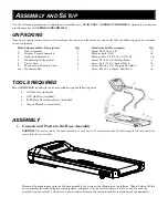
Page 2: ...8 Button Head 4 Screw 5 16 18 x 1 Socket Head 12 Screw 10 16 x 1 2 Tapping Pan Head 6 Screw M4 x 0 7 x 19mm Pan Head 14 TOOLS REQUIRED Most STAR TRAC treadmills can be assembled using the following tools 1 4 Hex Key included 5 32 Hex Key included 2 Phillips Head Screwdriver included Torque Wrench not included ASSEMBLY 1 Unpack and Position the Base Assembly CAUTION The motor end of the base assemb...

Page 3: ... Install all four bolts then tighten securely 3 Install the Display Console Locate and position the display console on the neck taking care not to pinch the display cable between the neck and the console Once the console is properly positioned secure the console to the neck using four 5 16 18 x 1 0 socket head bolts 5 16 lock washers and 5 16 flat washers Install all four bolts then tighten secure...

Page 4: ... handrail in similar manner 5 Connect the Display Cable Connect the main interface ribbon cable and DC power cable to corresponding connectors on the console At the treadmill base connect the main interface ribbon cable and DC power cable to the corresponding MCB connectors Note The S TRx models only has the main interface ribbon cable there is no DC power cable on these units MCB connector locati...

Page 5: ...orrect position with eight M4 x 0 7 x 19mm Pan Head Screws tighten all screws securely 7 Install Side Treads on Base Assembly Remove the paper layer of the adhesive tape located on the back of side tread plates now install the tread into position on the base assembly with one 10 16 x 1 2 tapping pan head screw Install the remaining tread in similar manner M4x19mm Pan Head Screw 10 16 x 1 2 Pan Hea...

Page 6: ...1 2 tapping pan head screws then secure the back end of cover to base assembly with two 10 16 x 1 2 tapping pan head screws Note Slide both handrail grommets down into position on the base assembly after motor top cover is installed 9 Install Motor Cover Trim Ring Snap the motor front cap on the motor shroud and slide the neck grommet down into position 10 16 x 1 2 Pan Head Screws ...

Page 7: ...d assembly of your STAR TRAC S SERIES TREADMILL ATTENTION Star Trac recommends that treadmills be spaced a minimum of 20 inches 0 5 m apart to allow safe and easy ingress and egress More importantly there must be at least 48 inches 1 5 m of free space behind the treadmills As with other motorized equipment the area where the treadmill is located must be free of obstacles and fixtures with sharp ed...

Reviews: