background image


Pro Bike 6000 Series 


Service Manual 

March 

2

0

, 200

6


Summary of Contents for Pro Bike 6000 Series

Page 1: ...Pro Bike 6000 Series Service Manual March 20 2006 ...

Page 2: ...4 Preliminary Service Manual Pro Bike 6000 Series Service Manual Table of Contents 1 Preventative Maintenance 2 Display Settings 3 Diagnostic Lights 4 Parts Diagrams This is a Preliminary Service Manual Additional volumes will follow as they become available ...

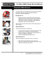
Page 3: ... liquid cleaner such as Formula 409 or FANTASTIK Wipe down the exterior of the display panel handle bars seat pedals shrouds and heart rate grips Note DO NOT spray the cleaner directly onto the display panel or heart rate grips Weekly Maintenance Perform the following services each week Vacuum the floor under and around the bike Move the bike to another spot if necessary to vacuum thoroughly Inspe...

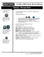
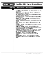
Page 4: ...and keys together 2 A beep will sound and the MANAGER SETTINGS will display momentarily in the information window 3 Release all keys SERIAL NUMBER will display in the information window The items that you may display and change Default values set in Serial Number Pro Bike serial number 0 Date Manufactures date for the Pro Bike 07 03 Display Vers 1 Display software version N A Display Vers 2 Displa...

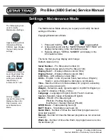
Page 5: ...indow The items that you may display and change Default values set in Serial Number Pro Bike serial number 0 Date Manufactures date for the Pro Bike 07 03 Display Vers 1 Display software version N A Display Vers 2 Display software version N A LCB Vers LCB software version N A Units English units of pounds miles feet inches English Metric units of kilograms kilometers centimeters Time Maximum time ...

Page 6: ... Fit Test Number of times the Fit Test program was run since last reset 0 Alpine Number of times the Alpine program was run since last reset 0 Rndm Prog Number of times the Random Hill program was run since last reset 0 Comm Lost Number of times a Comm Lost condition has occurred 0 Comm Lost occurs when communication between the Load Control Board LCB and display is lost Key Down Number of times a...

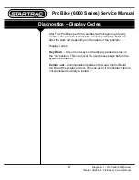
Page 7: ... problem is detected a message displays before or after the work out depending on the nature of the problem Display Codes Key Down One or more keys on the display panel are stuck in the on position This can occur if a user presses keys before the system is turned on Comm Lost Communication between the Load Control Board LCB and the display are lost This can occur if the display cable is not connec...

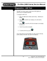
Page 8: ... the display assembly To engage the LED Test 1 Enter the Maintenance Mode see Settings Maintenance Mode 2 Press until LED Test is display in the information window 3 Press to enter the LED Test All lights on the display should be on 4 Check for any burned out lights 5 To exit the LED Test press If any of the LED s do not illuminate they may not be functioning and the display electronics may need t...

Page 9: ... engage the Keypad Test 1 Enter the Maintenance Mode see Settings Maintenance Mode 2 Press until Keypad Test is display in the information window 3 Press to enter the Keypad Test 4 Press each key on the display Each time you press a key the information window will display which key have pressed 5 To exit the keypad test press If any of the keys do not respond they may not be functioning and the di...

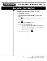
Page 10: ...fy heart rate operation 1 Enter the Maintenance Mode see Settings Maintenance Mode 2 Press until Heart Rate Test is display in the information window 3 Press to enter Heart Rate Test 4 The display will read TELEMETRY If checking contact heart rate it will read CONTACT and the heart rate number If checking Polar the display will read TELEMETRY and the heart rate number 5 To exit the heart rate test...

Page 11: ... Measurements can be done to verify the voltage of the battery To verify the battery voltage 1 Enter the Maintenance Mode see Settings Maintenance Mode 2 Press until Measurements is display in the information window 3 Press to enter Measurements 4 The display will read BATT VLT and the voltage of the battery 5 To exit the measurements press ...

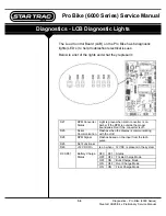
Page 12: ...esent D27 RPM Converter Status Light is green when main converter is on Amber if the RPM is outside the proper boundaries Red if the converter is off D25 Serial Communication Flashes when the display is communicating with the LCB D28 RPM Signal Flashes based on the input from the tach pulse D26 Not Functional D29 12 VDC On Is on when 12 VDC is present in the system D30 D31 Status OFF OFF Trickle C...

Reviews: