Quick-Start Guide
To view manuals, FAQs, videos, drivers, downloads, technical drawings, and more, visit www.startech.com/support.
Manual Revision: November 14, 2018 1:52 PM
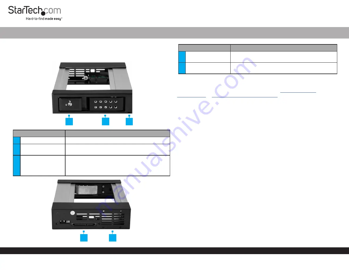
Product Diagram (HSB1SATSASBA/HSB1SATSASVA)
Component/LED
Function
1
Security Lock
• Used to secure/lock the Drive Door.
2
Drive Door
• Used to access the interior of the Hard Drive
Backplane
3
Power/Activity LED
•
Solid Blue:
the Hard Drive Backplane is receiving
power.
•
Flashing Purple:
The Hard Drive is being accessed
by the computer system.
3.5” SATA/SAS Hard Drive Backplane for 5.25” Bay | Trayless | Hot-Swap
1
Component
Function
4
SATA/SAS Connector
• Used to connect the Hard Drive Backplane to the
SATA/SAS power and data cables.
5
Fan Mounting Holes
• (Optional) Used to mount a fan onto the Hard Drive
Backplane.
Requirements
For the latest requirements and full manual, please visit
HSB1SATSASBA
or
www.startech.com/HSB1SATSASVA.
Installing the Backplane
Note:
Always handle storage devices with caution. Make sure that you’re properly
grounded by wearing an anti-static strap when you install any computer component.
1. Turn off your computer and any devices or peripherals that are connected to it.
2. Unplug the power cable from the back of your computer.
3. Disconnect any peripheral devices that are connected to your computer.
4. Open your computer case. For more information about how to do this, consult the
documentation that came with your computer system.
5. Remove the cover of an empty drive bay.
6. Insert the backplane into the empty drive bay slot, making sure that the screw holes
on the backplane are aligned with the holes in the drive bay.
7. Use the provided screws to secure the backplane to the drive bay.
8. Connect the SATA or SAS power and data cables to the SATA or SAS connector on
the backplane.
9. Place the cover back onto your computer case.
10. Reconnect the power cable to the back of your computer.
11. Reconnect any devices or peripherals that were connected to your computer.
12. Turn on your computer.
2
3
4
5


