Quick-Start Guide
To view manuals, FAQs, videos, drivers, downloads, technical drawings, and more, visit www.startech.com/support.
Manual Revision: February 27, 2019 9:51 AM
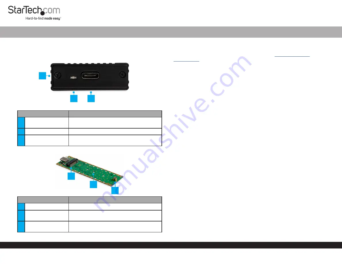
Product Diagram (M2E1BMU31C)
Exterior
Component
Function
1
Drive-Tray Screws x 2
• Used to secure the
Drive Tray
in the
Enclosure
.
2
Power LED
• Indicates that the Enclosure is receiving power.
3
USB-C Port
• Used to connect the
Enclosure
to the
Host
Computer
.
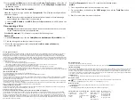
Interior
Component
Function
4
Drive Connector
• Used to connect the
Drive
to the
Enclosure
.
5
Adjustable Drive
Length Holes
• Used to accommodate different drive lengths.
6
Drive-Mount Screw/
Nut
• Used to secure the
Drive
to the
Enclosure
.
M.2 NVMe Enclosure | USB 3.1 (10Gbps) | USB-C
1
Requirements
For the latest requirements and full manual, please visit
Installation
Installing a Drive
Warning!
Drives should be handled carefully, especially when they’re transported. If
you’re not careful with your drives, you may lose data as a result.
1. Using a
Phillips Head Screwdriver,
remove the
Drive-Tray Screws
(x 2) from the
Enclosure
and remove the
Cover Plate
.
2. Carefully pull the
Drive Tray
out of the
Enclosure
.
3. Place the
Drive
next to the
Drive Tray
and align the screw groove on the
Drive
with
the
Adjustable Drive Length Holes
on the
Drive Tray
.
Note:
If the drive-mount hardware is already installed in the correct position, proceed
to step 6.
4. Use a
Phillips Head Screwdriver
(included) and a set of
Pliers
to remove the
Drive-
Mount Screw, Standoff,
and
Nut
.
5. Insert the
Standoff
and
Nut
into the correct
Adjustable Drive Length Hole
(80, 60,
42, or 30) according to the length of the
Drive
.
6. Using a set of
Pliers
tighten the
Standoff
and
Nut
.
7. Gently slide the connector on the
Drive
(on a 30-degree angle) into the
corresponding connector on the
Enclosure
.
Note:
The connector on your drive is keyed so that it only fits one way.
8. Lightly push the
Drive
down into position on the circuit board.
9. Insert the
Drive-Mount Screw
through the screw groove on the
Drive
and into the
Standoff
.
10. Using a
Phillips Head Screwdriver
tighten the
Drive-Mount Screw
, being careful
not to over-tighten.
11. Slide the
Drive Tray
into the center grooves in the enclosure so that the
USB-C Port
is facing outward.
12. Place the
Cover Plate
over the
USB-C Port
and circuit board.
2
4
3
6
5


