Instruction Manual
DE:
Bedienungsanleitung - de.startech.com
FR:
Guide de l'utilisateur - fr.startech.com
ES:
Guía del usuario - es.startech.com
IT:
Guida per l'uso - it.startech.com
NL:
Gebruiksaanwijzing - nl.startech.com
PT:
Guia do usuário - pt.startech.com
Manual Revision: 06/21/2012
For the most up-to-date information, please visit: www.startech.com
Packaging Contents
• 1x Top Panel
• 3x Bottom Panel
• 2x Side Panel and Frame
• 4x Cross Brace
• 8x Plastic Corner Caps
• 4x Casters
• 2x Sets of Keys
• 1x Bag M6 Cab Screws and Nuts
• 2x Allen Wrench
• 1x Assembly Screw Kit
• 4x Adjustable Feet
Required Tools
• Phillips (crosshead) screwdriver
• Adjustable wrench
RK2536BKF
25U 36in Knock-Down Server Cabinet with Casters
WARNING!
To prevent bodily injury, please ensure that the rack is
installed in a structurally sound environment with a level floor and
that all hardware has been assembled securely, and checked for
stability before loading equipment. When installing equipment into
the rack, start from the bottom of the rack first and move upwards,
keeping the heaviest equipment at the bottom to avoid a situation
where the rack becomes top-heavy.
Installation
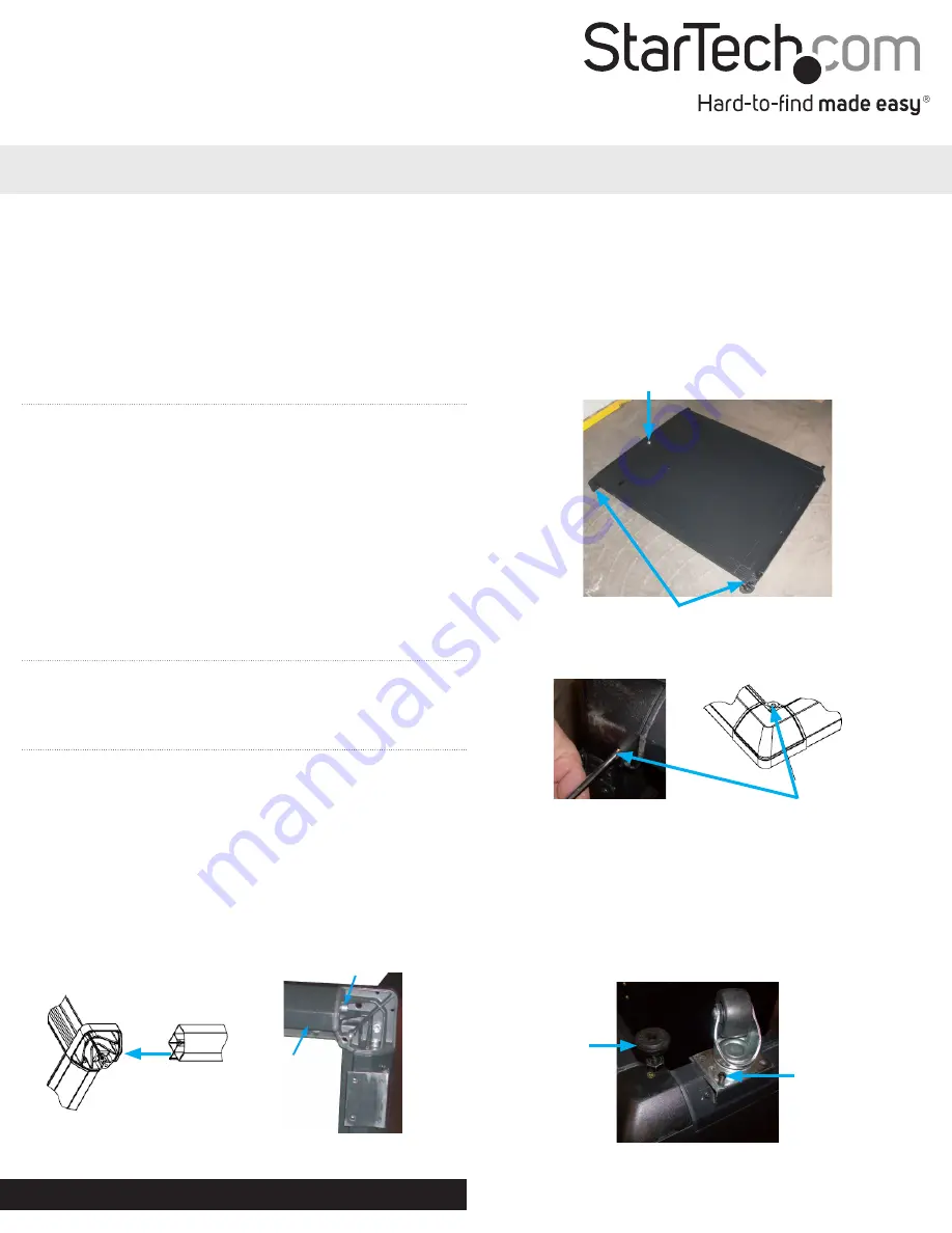
1. Connect the two side frames (with side doors) together using the 4
cross braces at each corner. Fasten using a large silver hex screw (M8)
at each end of the brace with the large Allen Wrench. Ensure that the
“fin” on the cross brace faces inwards. Attach the cross braces to one
side first, then attach the second side frame to the braces.
NOTE:
Make sure that the two side frames are right side up. Check
that the lock and latches on the side doors are on the same end as
well as the markings on the inner rack posts.
WARNING:
Before proceeding, ensure that
ALL
hex screws are
tightly wrench torqued to prevent accidental loosening during use.
Cross Brace
Cross Brace
Large Hex Screw
Corner Joints
Side Panel Lock
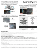
2. Place the Corner Caps over each of the 8 corner joints and fasten
them with flat-head M4 screws and a Phillips screwdriver.
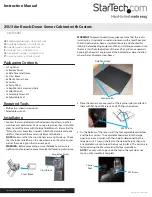
3. On the bottom of the rack, install the four adjustable corner feet
and the four casters. The adjustable feet screw into the large
openings in each corner with their height determined by the
large hex nut. Screw in the feet to the desired height, then use
an adjustable wrench to lock the hex nut in place. The casters are
fastened using the M5 screws and Phillips screwdriver.
NOTE:
You may wish to position the feet so the rack does not
move, until assembly is complete.
M4 Screw
M5 Screw
Corner
Feet